J26500003CalAmp Corp. Directed AP
CalAmp Corp.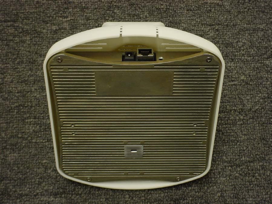
Click to zoom
Application Details
- Equipment Class
- DTS - Digital Transmission System
- Date of Grant
- Mar 29, 2005
- Application Purpose
- Original Equipment
- Date of Application
- Mar 29, 2005
- Equipment Note
- CalAmp Corp. Directed AP
- Frequency Range
- 2412.00000000 - 2462.00000000
- Company
- CalAmp Corp.
- Country
- United States
Documents & Files
Document Text
Text extracted from the exhibit documents filed with the FCC. Open a document above to read the original.
Users Manual
12/29/04© 2004 All Rights Reserved. 90-100tbd-000 Rev 1 (Preliminary 3) AS 1500 Intelligent RF AP Quick Installation Guide PRELIMINARY 3 Multi-Antenna Airespace Access Point Quick Installation Guide System Release x.x Print This Document This Guide contains several sections allowing you to install an AS 1500 (AS-1500-ABG-INT) Airespace Access Point. This model contains internal 802.11a and 802.11b/g antennas and no connectors for optional external antennas. •Overview •Step 1: Collecting Required Tools and Supplies •Step 2: Configuring the Airespace AP Before Installation •Step 3: Preparing Mounting Locations •Step 4: Mounting the Airespace APs •Step 5: Returning MAC Information •Planning Notes •FCC Statements for Airespace APs ATTENTION!Special Considerations While Airespace Access Points have been engineered for easy installation, there are some guidelines that are very important to the end users: •PLACE Airespace Access Points NO MORE THAN 140 FEET APART FROM EACH OTHER. Placing Airespace APs further apart almost always results in poor coverage. •DO NOT MOUNT Airespace APs OUTSIDE BUILDINGS. •DO NOT MOUNT Airespace APs ON BUILDING PERIMETER WALLS UNLESS THE OPERATOR WANTS TO PROVIDE COVERAGE OUTSIDE THE BUILDING. •MAKE SURE that plenum-mounted Airespace APs are powered using Power Over Ethernet (POE) and use only the metal brackets (not the Ceiling-Mount Base or the Hanging-Ceiling Clips) to comply with safety regulations. •MAKE SURE THAT THE Airespace Access Points ARE INSTALLED VERTI- CALLY. Airespace Access Points ARE DESIGNED TO BE INSTALLED VERTICALLY, either standing up in a plenum or hanging from a ceiling, to create the largest coverage area per Airespace AP. Hanging the Airespace AP from the ceiling provides the best RF coverage. 12/29/04Overview 90-100tbd-000 Rev 1 (Preliminary 3)2 •DO NOT MOUNT Airespace Access Point ANTENNAS WITHIN ONE METER (3 FT.) OF ANY METAL OBSTRUCTIONS. THE RF WAVES FROM Airespace Access Points ARE BLOCKED AND/OR REFLECTED BY METAL OBJECTS, such as metal HVAC ducts, conduit, pipes, bookcases, elevator shafts, stairwells, and metal walls. REFER TO THE Airespace Access Point Deployment Guide BEFORE MOUNTING Airespace APs NEAR METAL OBSTRUCTIONS. OverviewOverview This guide is designed to provide you with the information needed to mount AS 1500 Airespace Access Points (Airespace APs). Airespace APs are part of the innovative Airespace Wireless Enterprise Platform (Airespace System), and require no manual configuration after they are mounted. This document assumes that a site survey has been performed as described in the Airespace Access Point Deployment Guide section in the Airespace Product Guide, that Airespace AP locations have been selected, and that you have one Airespace AP per indicated location. After the site survey is done, you should have a map indicating the following: •AP locations in the middle of a ceiling or hallway. •AP power options: power supplied by the AC-to-DC power supply orderable from the factory, or Power over Ethernet (PoE) from the Airespace WLAN Switch, another network device, or a PoE injector/hub (usually located in a wiring closet). If you do not have a map, make one so you can record the MAC addresses from each location and return them to the to the person who is planning or managing this wireless network. Refer to the following sections to install the Airespace APs. For more details about Airespace AP installations, refer to the Planning Notes section at the end of this document. Step 1: Collecting Required Tools and SuppliesStep 1: Collecting Required Tools and Supplies •One Airespace AP per location with included mounting clips. •Optional Airespace AP Mounting Kits, factory-orderable. •Optional external AC-to-DC power supplies, factory-orderable. •Map showing Airespace AP locations and power options. •Screwdrivers, drills, and ladder. •CAT-5 (or higher) cables to connect the Airespace AP locations and the Airespace WLAN Switch or other network device. Continue with Step 2: Configuring the Airespace AP Before Installation . Note: Plenum-mounted Airespace APs and REAPs MUST BE powered using Power Over Ethernet (POE) to comply with safety regulations. Note: When mounting Airespace APs, make sure to maintain a 20 cm (8 in.) separa- tion between the Airespace APs and bystanders to comply with FCC RF exposure regulations. Refer to the FCC Statements for Airespace APs section for more information. 12/29/04Step 2: Configuring the Airespace AP Before Installation 90-100tbd-000 Rev 1 (Preliminary 3)3 Step 2: Configuring the Airespace AP Before InstallationStep 2: Configuring the Airespace AP Before Installation The following procedures are designed to make sure that your Airespace AP physical installation goes smoothly and that initial operation is as expected. If you are unable to prepare your Airespace AP for deployment, this Step also describes RMA (Return Material Authorization) procedures. Configuration SetupConfiguration Setup Configuration Steps for an Airespace APConfiguration Steps for an Airespace AP 1.Configure the Airespace Switch or Appliance for LWAPP Layer 2 Mode (use the CLI command show switchconfig to determine the mode; if it is set to layer 3, use the CLI command config switchconfig mode L2 to change it to Layer 2). Make sure the Airespace Switch or Appliance DS Port is connected to the network. Use CLI, Web Browser and/or ACS procedures as described in the Airespace Switch and Appliance Quick Installation Guide Airespace Switch and Appliance Quick Install Guide and the Airespace Product GuideAirespace Product Guide. -Make sure AP ports are available (either Direct-Connect Mode through the Switch physical ports, or in Appliance Mode through the Airespace Switch or Appliance Management/AP-Manager Interface). -Set the Airespace Switch or Appliance as the Master, so new Airespace APs always associate with it. Use the CLI command show network config to determine if the Airespace Switch or Appliance DS Port is the…
Text truncated - open the document above for the full version.
External Photos
External Photos Shroud corner Shroud top view Shroud top & front Shroud bottom
ID Label/Location Info
REVISIONS UNLESS OTHERWISE SPECIFIED DIMENSIONS ARE IN INCHES TOLERANCES ARE: FRACTIONS DECIMALS ANGLES ±1/32 .XX ±.01 ±0°30’ XXX ± .005 USED ON Elec.File: 132669_expiremental.doc MATERIAL FINISH DRAWN: CHECKED: ISSUED: TITLE DO NOT SCALE DRAWING SIZE CAGE CODE DWG NO. REV A 6T925 SHEET 1 OF 1 SCALE WEIGHT ITEM NO. QTY REQD IDENTIFYING NO. DESCRIPTION 1 1 79-00125 LABEL, REGULATORY, 3.0 X 0.5 NOTES: APPLICABLE STANDARDS/SPECIFICATIONS: MIL-STD-100E, ENGINEERING DRAWING PRACTICES. ANSI Y14.5M-82, DIMENSIONS AND TOLERANCES. MATERIAL TYPE : FLEXCON BLANK SILVER POLYESTER INK TYPE: BLACK RESIN RIBBON TYPE : SONY 4070 PRINTER TYPE: SATO 8450 OR ZEBRA 110 RECOMMENDED MANUFACTURER UL FILE: MH16635 REV ECO NO. DESCRIPTION DATE APPROVED 1 Preliminary 2 Add FCC & UL information 3 Update to include FCC ID and compliance statement. Revised layout. 2/28 Exp2 Updated based on TUV review comments. Removed FCC logo and added compliance statement. Increased label size to 3.0” x 0.5”. Changed titles. 3/1 M. Anderson 3/1/05 132669 1 LABEL, REGULATORY, ORION-LITE 1/1 Form No: L11041/A 500003 I.T.E. Power In: 48V 270mA LISTED AIRESPACE 1500 FCC ID: J26500003 54XT E228255 This device complies with Part 15 of the FCC Rules. Operation is subject to the following two conditions: (1) this device may not cause harmful interference, and (2) this device must accept any interference received, including interference that may cause undesired operation. 3.00 0.50 Label Placement
Internal Photos
Internal Pictures Top shield Bottom Shield 1 Bottom Shield 2 No shield – top rear No shroud – top corner No shroud – top rear 132577 board top 132577 board bottom 132621 board top 132621 board bottom
Test Report
PRODUCT SERVICE TEST RESULT SUMMARY FCC PART 15 SUBPART C Section 15.247 FCC PART 15 SUBPART C Section 15.207 Conducted Emission Requirements Industry Canada RSS-210: Issue 5: 2001 A1: Nov. 2002, A2: Apr. 2003, A3: 2004, A4: 2004 Section 6.2.2(o) MANUFACTURER'S NAME CalAmp Corporation NAME OF EQUIPMENT CalAmp Corp. (CA) Directed AP (Airespace AeS IRAP) TYPE OF EQUIPMENT Wireless LAN Access Point MODEL NUMBER CA 500003 (AeS 1500) MANUFACTURER'S ADDRESS 1401 N. Rice Avenue Oxnard CA 93030 TEST REPORT NUMBER WC500164 RevA TEST DATE 27 January 2005, 01, 02, 03, 05 February 2005, 17 March 2005 According to testing performed at TÜV Product Service Inc, the above-mentioned unit is in compliance with the electromagnetic compatibility requirements defined in FCC Part 15 Subpart C Sections 15.207 and 15.247, and also with RSS-210, section 6.2.2(o). It is the manufacturer's responsibility to assure that additional production units of this model are manufactured with identical electrical and mechanical characteristics. Any modifications necessary for compliance made during testing on the above mentioned date(s) must be implemented in all production units for compliance to be maintained. TÜV Product Service Inc, as an independent testing laboratory, declares that the equipment tested as specified above conforms to the requirements of FCC Part 15 Subpart C Sections 15.207 and 15.247, and also with RSS- 210, section 6.2.2(o). Date: 21 February 2005 Location: Taylors Falls MN J. C. Sausen T. K. Swanson USA Tested By Reviewed By Not Transferable File No. WC500164 RevA, Page 1 of 128 TÜV PRODUCT SERVICE INC 19333 Wild Mountain Road Taylors Falls MN 55084-1758 Tel: 651 638 0297 Fax: 651 638 0298 Rev.No 1.0 PRODUCT SERVICE EMC EMISSION - T E S T R E P O R T Test Report File No. : WC500164 RevA Date of issue: 21 February 2005 Model No. : CA 500003 (AeS 1500) Product Name : CalAmp Corp. (CA) Directed AP (Airespace AeS IRAP) Product Type : Wireless LAN Access Point Applicant : CalAmp Corporation Manufacturer : CalAmp Corporation License holder : CalAmp Corporation Address : 1401 N. Rice Avenue : Oxnard CA 93030 Test Result : Positive Negative Test Project Number : Reference(s) WC500164 RevA Total pages 128 TÜV Product Service Inc is a subcontractor to TÜV Product Service, GmbH according to the principles outlined in ISO/IEC Guide 25 and EN 45001. TÜV Product Service Inc reports apply only to the specific samples tested under stated test conditions. It is the manufacturer's responsibility to assure that additional production units of this model are manufactured with identical electrical and mechanical components. TÜV Product Service Inc shall have no liability for any deductions, inferences or generalizations drawn by the client or others from TÜV Product Service Inc issued reports. This report is the confidential property of the client. As a mutual protection to our clients, the public and ourselves, extracts from the test report shall not be reproduced except in full without our written approval. This report shall not be used by the client to claim product endorsement by NVLAP or any agency of the US government. TÜV Product Service Inc and its professional staff hold government and professional organization certifications and are members of AAMI, ACIL, AEA, ANSI, IEEE, NVLAP, and VCCI File No. WC500164 RevA, Page 2 of 128 TÜV PRODUCT SERVICE INC 19333 Wild Mountain Road Taylors Falls MN 55084-1758 Tel: 651 638 0297 Fax: 651 638 0298 Rev.No 1.0 PRODUCT SERVICE REVISION RECORD REVISION TOTAL NUMBER OF PAGES DATE DESCRIPTION 112 21 February 2005 Initial Release A 128 21 March 2005 Revisions include: Added test setup diagram and equipment information for conducted emissions setup – Page 19. Updated the conducted out of band emissions data to show the conducted limit – Pages 50 - 92. Added radiated emissions in the restricted bands with both transmitters operating simultaneously – Pages 109 - 112. File No. WC500164 RevA, Page 3 of 128 TÜV PRODUCT SERVICE INC 19333 Wild Mountain Road Taylors Falls MN 55084-1758 Tel: 651 638 0297 Fax: 651 638 0298 Rev.No 1.0 PRODUCT SERVICE TABLE OF CONTENTS General Information Page(s) Revision Record 2 Test Regulations 4 Emission Test Results 5 - 6 Measurement Protocol 7 - 8 Deviations / Summary 9 Constructional Data Form(s) and/or Product Information Form(s) 10 - 17 Cal Amp Test Set up Diagram 18 - 19 Test data Part 15 Section RSS-210 Section Maximum Power Output 15.247 (b)(3) 6.2.2(o)(b) 21 - 31 6 dB Bandwidth 15.247 (a)(2) 6.2.2(o) Amd.1 (IV) 32 - 38 99% Bandwidth N/A 5.9.1 39 - 45 Power Spectral Density 15.247 (e) 6.2.2(o) Amd.1 (IV) 46 - 49 Conducted Out of Band Emissions 15.247 (d) 6.2.2(o)(e1) 50 - 92 Radiated Emissions in Restricted Bands 15.247 (d) 6.3 (c) – N/A 93 - 112 Radiated Emissions in Restricted Bands (2.4 GHz Band edges) 15.247 (d) N/A 113 - 121 AC Line Conducted Emissions 15.207 CISPR 22 122 - 127 Receiver Spurious Radiated Emissions 15.109 N/A 128 File No. WC500164 RevA, Page 4 of 128 TÜV PRODUCT SERVICE INC 19333 Wild Mountain Road Taylors Falls MN 55084-1758 Tel: 651 638 0297 Fax: 651 638 0298 Rev.No 1.0 PRODUCT SERVICE EMISSIONS TEST REGULATIONS : The emissions tests were performed according to following regulations: -------------------------------------------------------------------------------- - EN 50081-1 / 1991 - EN 55011 / 1998 - Group 1 - Group 2 w/Amendment A1:1999 - Class A - Class B - EN 55013 / 1990 - EN 55014 / 1987 - Household appliances and similar - Portable tools - Semiconductor devices - EN 55014 / A2:1990 - EN 55014 / 1993 - Household appliances and similar - Portable tools - Semiconductor devices - EN 55015 / 1987 - EN 55015 / A1:1990 - EN 55015 / 1993 - EN 55022 / 1987 - Class A - Class B - FCC Part 15 Subpart C Section 15.247 - FCC Part 15 Subpart C Section 15.207 Conducted Emission Requirements - RSS-210, Issue 5, 2001 – Section 6.2.2(o) File No. WC500164 RevA, Page 5 of 128 TÜV…
Text truncated - open the document above for the full version.
Test Report
File No. WC500164 RevA, Page 50 of 128 TÜV PRODUCT SERVICE INC 19333 Wild Mountain Road Taylors Falls MN 55084-1758 Tel: 651 638 0297 Fax: 651 638 0298 Rev.No 1.0 PRODUCT SERVICE Conducted Out of Band Emissions Specifications: FCC Specification: Paragraph: 15.247 (d) IC Specification: RSS-210, 6.2.2(o)(e1) The Out of Band Emission measurements were performed at the following test location: - Test not applicable - Wild River Lab Large Test Site (Open Area Test Site) - Wild River Lab Small Test Site (Open Area Test Site) - Oakwood Lab (Open Area Test Site) - Wild River Lab Screen Room - Cal Amp File No. WC500164 RevA, Page 51 of 128 File No. WC500164 RevA, Page 52 of 128 File No. WC500164 RevA, Page 53 of 128 File No. WC500164 RevA, Page 54 of 128 File No. WC500164 RevA, Page 55 of 128 File No. WC500164 RevA, Page 56 of 128 File No. WC500164 RevA, Page 57 of 128 File No. WC500164 RevA, Page 58 of 128 File No. WC500164 RevA, Page 59 of 128 File No. WC500164 RevA, Page 60 of 128 File No. WC500164 RevA, Page 61 of 128 File No. WC500164 RevA, Page 62 of 128 File No. WC500164 RevA, Page 63 of 128 File No. WC500164 RevA, Page 64 of 128 File No. WC500164 RevA, Page 6 5 of 128 File No. WC500164 RevA, Page 66 of 128 File No. WC500164 RevA, Page 67 of 128 File No. WC500164 RevA, Page 68 of 128 File No. WC500164 RevA, Page 69 of 128 File No. WC500164 RevA, Page 70 of 128 File No. WC500164 RevA, Page 71 of 128 File No. WC500164 RevA, Page 72 of 128 File No. WC500164 RevA, Page 73 of 128 File No. WC500164 RevA, Page 74 of 128 File No. WC500164 RevA, Page 7 5 of 128 File No. WC500164 RevA, Page 76 of 128 File No. WC500164 RevA, Page 77 of 128 File No. WC500164 RevA, Page 78 of 128 File No. WC500164 RevA, Page 79 of 128 File No. WC500164 RevA, Page 80 of 128 File No. WC500164 RevA, Page 81 of 128 File No. WC500164 RevA, Page 82 of 128 File No. WC500164 RevA, Page 83 of 128 File No. WC500164 RevA, Page 84 of 128 File No. WC500164 RevA, Page 8 5 of 128 File No. WC500164 RevA, Page 86 of 128 File No. WC500164 RevA, Page 87 of 128 File No. WC500164 RevA, Page 88 of 128 File No. WC500164 RevA, Page 89 of 128 File No. WC500164 RevA, Page 90 of 128 File No. WC500164 RevA, Page 91 of 128 File No. WC500164 RevA, Page 92 of 128 File No. WC500164 RevA, Page 93 of 128 TÜV PRODUCT SERVICE INC 19333 Wild Mountain Road Taylors Falls MN 55084-1758 Tel: 651 638 0297 Fax: 651 638 0298 Rev.No 1.0 PRODUCT SERVICE Radiated Emissions in Restricted Bands Specifications: FCC Specification: Paragraph: 15.247 (d) IC Specification: N/A The Radiated Emissions in Restricted Band measurements were performed at the following test location: - Test not applicable - TUV America Wild River Lab Large Test Site (Open Area Test Site) - Wild River Lab Small Test Site (Open Area Test Site) - Oakwood Lab (Open Area Test Site) - Wild River Lab Screen Room - Cal Amp Test Equipment Used: TUV ID Model Number Manufacturer Description Serial Number Cal Due - 3204 EM-6917B Electro-Metrics Biconicalog Periodic 102 21-Oct-05 2682 85650A Hewlett-Packard Quasi-Peak Adapter 2811A01127 14-Aug-05 - 2689 8566B Hewlett-Packard Spectrum Analyzer 2416A00321 31-Jan-05 - 2674 85662A Hewlett-Packard Analyzer Display 2050A02007 31-Jan-05 - 3962 ZHL-1042J Mini-Circuits Preamplifier D120403-2 Code B 08-Feb-05 - 3957 SL18B4020 Phase One Microwave Preamplifier 1 – 18 GHz 0001 Code B 17-Oct-05 - 2075 3115 Electro-Mechanics (EMCO) Ridge Guide Ant. 1-18 GHz 9001-3275 24-Nov-05 - 2478 AWT-18037 Avantek Preamplifier 8-18 GHz 1001-9226 Code B 24-May-05 - 2862 8491A Hewlett Packard 6 dB Attenuator 7268 Code B 21-Jun-05 - 2835 8491A Hewlett Packard 3 dB Attenuator 8021 Code B 21-Jun-05 - 3933 F551B-1 Acronetics 8 – 12 GHz Bandpass Filter 010 Code B 17-Oct-05 - 3997 EWT-14-0066 EWT 2.4 GHz Notch Filter E2 Code B 19Jan-06 - 3935 F548B-1 Acronetics 1 – 2 GHz Bandpass Filter 010 Code B 17-Oct-05 - 2127 11975A Hewlett Packard Amplifier 2- 8 GHz 2738A01200 Code B 25-May-05 - 2661 11970A Hewlett-Packard Harm Mixer – 26.5-40 GHz 2332A01861 11-Jul-06 - 2662 11970K Hewlett-Packard Harm Mixer – 18-26.5 GHz 2332A01170 11-Jul-06 - 2919 11970U Hewlett-Packard Harm Mixer – 40-60 GHz 3003A01395 11-Jul-06 - 2788 3116 Electro-Mechanics (EMCO) Ridge Guide Ant 18-40 GHz 2005 27-Sep-05 - 2918 19-7025 Hewlett-Packard Horn Antenna – 40-60 GHz N/A Cal Code B = Calibration verification performed internally. Cal Code Y = Calibration not required when used with other calibrated equipment. All measurement instrumentation is traceable to the National Institute of Standards and Technology (NIST) and is calibrated annually. RADIATED EMISSIONS Test Report #: WC500164 Run 4 Test Area: LTS EUT Model #: DIRECTED AP Date: 1/27/05 EUT Serial #: Unit "A" EUT Power: 48VDC (POE) Temperature: 23.0 °C Test Method: FCC A Air Pressure: 99.0 kPa Customer: CALAMP Rel. Humidity: 20.0 % EUT Description: WIRELESS ACCESS POINT (802.11A) Notes: PA's set to min power. Beacon Mode. With outlet mounted p/s attached. Data File Name: 0164.dat Page: 1of 6 Tested by: JCS Printed Signature Reviewed by: TKS Printed Signature List of measurements for run #: 4 FREQ LEVEL (dBuV) CABLE / ANT / PREAMP / ATTEN (dB) FINAL (dBuV / m) POL / HGT / AZ (m)(DEG) DELTA1 FCC-A <1GHz 10m DELTA2 720 MHz maxed: 720.0 MHz 36.15 Qp 4.07 / 20.19 / 26.76 / 0.1 33.75 V / 2.60 / 158 -12.65 n/a 720.0 MHz 37.24 Qp 4.07 / 20.19 / 26.76 / 0.1 34.84 V / 2.60 / 158 -11.56 n/a 42.614 MHz 45.07 Qp 0.8 / 15.74 / 25.9 / 0.0 35.71 V / 1.00 / 158 -3.39 n/a 50.414 MHz 44.83 Qp 0.9 / 13.16 / 25.9 / 0.0 32.99 V / 1.00 / 158 -6.11 n/a 120.009 MHz 50.1 Qp 1.48 / 8.11 / 25.96 / 0.0 33.74 V / 1.00 / 158 -9.76 n/a 110.001 MHz 45.65 Qp 1.4 / 8.4 / 25.96 / 0.0 29.49 V / 1.00 / 158 -14.01 n/a 130.001 MHz 37.2 Qp 1.6 / 7.75 / 26.08 / 0.0 20.48 V / 1.00 / 158 -23.02 n/a 160.001 MHz 50.75 Qp 1.7 / 8.09 / 25.98 / 0.0 34.56 V / 1.00 / 158 -8.94 n/a 200.001 MHz 41.6 Qp 2.0 / 10.0 / 26.3 / 0.1 27.4 V / 1.00 / 158 -16.1 n/a 220.001 …
Text truncated - open the document above for the full version.
Test Setup Photos
TEST SETUP FOR EMISSIONS TESTING WILD RIVER LAB Large Test Site Notes: 1.Items shown in dotted lines are located on the floor below the test area. It is 5 meters vertically from the ground floor to the test area. 2.50 Hz, 60 Hz, and 400 Hz are power panels for alternating current. 3.The antenna may be positioned horizontally 3, 10 or 30 meters from the center of the turntable. 4.The circle is a 6.7 meter diameter turntable. 5.A ground plane is in the plane of this sheet. 6.The test sample is shown in the azimuthal position representing zero degrees. EUT 0 90270 180 60 Hz 50 Hz 400 Hz Shielded Enclosure ANTENNA Radiated Emissions Conducted Emissions
Contact Information
Applicant
Steve Hall(Director of Technology)
Test Firm
TUV SUD America - Product ServiceJoel Schneider
Technical Specifications
| # | Rule Parts | Frequency Range | Power Output |
|---|---|---|---|
| 1 | 15C | 2.41 GHz - 2.46 GHz | 138.00 mW |
Other Applications from CalAmp Corp.

J26-4859300114
Feb 24, 2014LTE PCI-e Moudular
Equipment Class
JBP - Part 15 Class B Computing Device Peripheral
J26-PC-UC-2
May 16, 2012OSMAC Base Station
Equipment Class
TNB - Licensed Non-Broadcast Station Transmitter
J26520038
Sep 03, 2003Ecco Mustang PCS Amplifier
Equipment Class
AMP - Amplifier
J26-530009
Mar 16, 2003MMDS Wireless Modem, 530009
Equipment Class
TNB - Licensed Non-Broadcast Station Transmitter
J26520031-2
Sep 30, 2001MMDS/MMDS Low TX In-Band Transceiver
Equipment Class
TNB - Licensed Non-Broadcast Station Transmitter