J26520038Ecco Mustang PCS Amplifier
CalAmp Corp.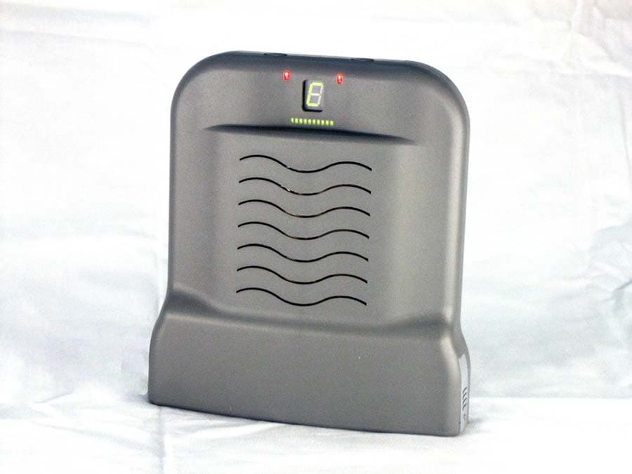
Click to zoom
Application Details
- Equipment Class
- AMP - Amplifier
- Date of Grant
- Sep 03, 2003
- Application Purpose
- Original Equipment
- Date of Application
- Sep 03, 2003
- Equipment Note
- Ecco Mustang PCS Amplifier
- Frequency Range
- 1930.00000000 - 1990.00000000
- Company
- CalAmp Corp.
- Country
- United States
Documents & Files
Document Text
Text extracted from the exhibit documents filed with the FCC. Open a document above to read the original.
Users Manual
Ecco User Guide Introduction The requirement for reliable, always-on PCS phone coverage continues to increase dramatically. However, it is not unusual to encounter areas within a residence or other building where it’s difficult to receive consistent coverage. The Ecco TM is a powerful and sophisticated cost-effective signal repeater that augments PCS coverage. This simple-to-use device is specifically designed for use in a residence, small office or other in-building application. Ecco has advanced software that adjusts various performance parameters based on the ever-changing RF environment and its compact form factor is aesthetically designed to blend into any home or office decor. Product Placement Installing the Ecco is simple and requires no tools, test equipment or RF knowledge. The Ecco must be located by a window with access to a standard household outlet. To receive maximum product performance, you’ll need to locate the window location with the strongest signal. Using your current Sprint PCS phone (make sure it’s powered on), check the signal strength meter at each window location. At the window location with the strongest signal, place the Ecco repeater on the window sill, or nearby table, counter or other convenient location with the LED display facing indoors. Power button Tx indicator Band Select button Low battery indicator Current Band display Signal Strength display Product Configuration Plug in the AC adapter to the outlet and connect to the Ecco repeater. Turn on the device by pressing the “Power” button. Consult the table below to identify the appropriate signal band (“A”, “B”, “C”, “D”, “E”, or “F”) for your Sprint PCS market. Now select the appropriate PCS signal band on the Ecco by pressing the “Band Select” button until the desired band is lit up in the “Current Band” display. At this time, the product is in installation mode and the “Current Band” display will be flashing. Wait approximately 10 seconds, then briefly turn the unit off and back on with the power button. The “Current Band” display should now be solid (not flashing) and the Ecco is now fully operational. Battery Backup The Ecco is normally powered by the included 6V DC plug-in power supply. It also facilitates six (6) standard AA alkaline batteries in the compartment on the side that serve as backup in case of power failure. Under battery power, the device will run for approximately 15 minutes. Troubleshooting Still having trouble? 9 Is the LED display of the Ecco facing indoors and away from the window? 9 Is the appropriate signal band (“A”, “B”, “C”, “D”, “E”, or “F”) for your Sprint PCS market shown in the “Current Band” display? 9 Is the “Current Band” display lit solid (not flashing)? Insert US map with applicable frequency bands
Users Manual
CONFIDENTIAL INFORMATION ECCO TM Consumer Electronic Repeater June 15, 2003 CONFIDENTIAL INFORMATION Page 2 of 3 Introduction California Amplifier’s Consumer Electronic Repeater, called “Ecco”, is a compact, cost-effective, consumer repeater product designed to complement PCS wireless infrastructure. This product enhances in-building PCS coverage on a trouble-spot basis, to multiple simultaneous users. Ecco TM is transparent to the network because it enhances coverage without the use of additional frequencies, alleviating complex frequency planning. By employing various patent pending technologies, California Amplifier has integrated this functionality into a single, self-contained device. Since Ecco requires no mounting hardware or difficult installation for use, it is perfectly suited for consumer deployment in a residence, SOHO or other in-building application. Ecco is targeted for use by PCS carriers and may either be provided or sold to PCS customers, the end user. Ecco provides an affordable solution to decrease customer voluntary churn caused by spotty coverage and also increase revenue potential by providing cost-effective and reliable in-building coverage. Additionally, Ecco provides an opportunity to attack the landline replacement market using wireless, by enhancing availability and reliability of the wireless link in residences. Product Operation Ecco incorporates a high gain antenna that is intended to be directed toward signal paths to / from the base station (called “Donor Antenna”), and a second high gain antenna that is intended to be directed towards the interior of the service location (called “Server Antenna”). Ecco contains electronics that amplify signals between these antennas, in the specific channel block of interest. The design and packaging of the two antennas in Ecco have been optimized to maximize their isolation, thus accommodating a high gain electronic amplifier. In order to aid the consumer in orienting the device to optimize signal paths to / from the base station, Ecco has visual status indicators. These indicators inform a user that the device is receiving sufficient PCS RF signal to provide enhancement, and an indication of the strength of that signal. The display also provides visual indication if a PCS RF signal does not exist or if the quality of the signal received is too poor for Ecco to enhance coverage. Ecco employs an adaptive gain control algorithm which continually and automatically optimizes the gain based on a variety of conditions related to the ever-changing surrounding RF environment. This adaptive approach simplifies the product's placement and also eliminates any ongoing need for monitoring, adjustment or reconfiguration by the customer. Ecco has a “Power” button, which toggles the unit on and off. It also has a “Band Select” button which allows the user to select the desired PCS frequency block, CONFIDENTIAL INFORMATION Page 3 of 3 based on licenses in a given market. The selection of a specific frequency block balances the desire to boost performance, simplify device placement by the consumer, and provide a single standardized product that can be used nationally. The “Band Selection” provides seven settings, corresponding to blocks A through F, where the B block is divided into two pieces. Ecco understands that the A-C channel blocks are 15 MHz wide and the D – F blocks are 5 MHz wide, and filters the signals accordingly. Ecco TM hides the sophistication of its functions with advanced self-diagnostic software, thus providing a simple to use, consumer product. Ecco is equipped with self-diagnostics designed to detect a variety of problem conditions, including oscillation (typically due to feedback of signals between the antennas), overdriving the unit (typically due to use of the unit too close to a base station or use of a handset too close to Ecco), and general device failure. Under these and other error conditions, Ecco automatically attempts to correct the problem by adjusting various internal functional controls. If the unit is unable to resolve the error condition, it renders itself inoperable, but allows the consumer to diagnose the problem through the use of displayed error codes. Ecco continuously detects the presence of PCS signal and shuts the power amplifiers off in the absence of signal. This function helps the overall system performance by reducing the aggregated system noise floor. Product Appearance The dimensions of Ecco are approximately 7.4” x 8.2” x 3.0” (width, height, depth) and it weighs approximately 2 pounds without batteries. This size is primarily dictated by the isolation requirements between the Server and Donor Antennas. Ecco is designed to blend into any home or office with an aesthetically pleasing look comparable to today’s small consumer electronic equipment. Ecco LED Panel View
Users Manual
Ecco User Guide Introduction The requirement for reliable, always-on PCS phone coverage continues to increase dramatically. However, it is not unusual to encounter areas within a residence or other building where it’s difficult to receive consistent coverage. The Ecco TM is a powerful and sophisticated cost-effective signal repeater that augments PCS coverage. This simple-to-use device is specifically designed for use in a residence, small office or other in-building application. Ecco has advanced software that adjusts various performance parameters based on the ever-changing RF environment and its compact form factor is aesthetically designed to blend into any home or office decor. Product Placement Installing the Ecco is simple and requires no tools, test equipment or RF knowledge. The Ecco must be located by a window with access to a standard household outlet. To receive maximum product performance, you’ll need to locate the window location with the strongest signal. Using your current Sprint PCS phone (make sure it’s powered on), check the signal strength meter at each window location. At the window location with the strongest signal, place the Ecco repeater on the window sill, or nearby table, counter or other convenient location with the LED display facing indoors. Power button Tx indicator Band Select button Low battery indicator Current Band display Signal Strength display Product Configuration Plug in the AC adapter to the outlet and connect to the Ecco repeater. Turn on the device by pressing the “Power” button. Consult the table below to identify the appropriate signal band (“A”, “B”, “C”, “D”, “E”, or “F”) for your Sprint PCS market. Now select the appropriate PCS signal band on the Ecco by pressing the “Band Select” button until the desired band is lit up in the “Current Band” display. At this time, the product is in installation mode and the “Current Band” display will be flashing. Wait approximately 10 seconds, then briefly turn the unit off and back on with the power button. The “Current Band” display should now be solid (not flashing) and the Ecco is now fully operational. Battery Backup The Ecco is normally powered by the included 6V DC plug-in power supply. It also facilitates six (6) standard AA alkaline batteries in the compartment on the side that serve as backup in case of power failure. Under battery power, the device will run for approximately 15 minutes. Troubleshooting Still having trouble? 9 Is the LED display of the Ecco facing indoors and away from the window? 9 Is the appropriate signal band (“A”, “B”, “C”, “D”, “E”, or “F”) for your Sprint PCS market shown in the “Current Band” display? 9 Is the “Current Band” display lit solid (not flashing)? Insert US map with applicable frequency bands
Users Manual
CONFIDENTIAL INFORMATION ECCO TM Consumer Electronic Repeater June 15, 2003 CONFIDENTIAL INFORMATION Page 2 of 3 Introduction California Amplifier’s Consumer Electronic Repeater, called “Ecco”, is a compact, cost-effective, consumer repeater product designed to complement PCS wireless infrastructure. This product enhances in-building PCS coverage on a trouble-spot basis, to multiple simultaneous users. Ecco TM is transparent to the network because it enhances coverage without the use of additional frequencies, alleviating complex frequency planning. By employing various patent pending technologies, California Amplifier has integrated this functionality into a single, self-contained device. Since Ecco requires no mounting hardware or difficult installation for use, it is perfectly suited for consumer deployment in a residence, SOHO or other in-building application. Ecco is targeted for use by PCS carriers and may either be provided or sold to PCS customers, the end user. Ecco provides an affordable solution to decrease customer voluntary churn caused by spotty coverage and also increase revenue potential by providing cost-effective and reliable in-building coverage. Additionally, Ecco provides an opportunity to attack the landline replacement market using wireless, by enhancing availability and reliability of the wireless link in residences. Product Operation Ecco incorporates a high gain antenna that is intended to be directed toward signal paths to / from the base station (called “Donor Antenna”), and a second high gain antenna that is intended to be directed towards the interior of the service location (called “Server Antenna”). Ecco contains electronics that amplify signals between these antennas, in the specific channel block of interest. The design and packaging of the two antennas in Ecco have been optimized to maximize their isolation, thus accommodating a high gain electronic amplifier. In order to aid the consumer in orienting the device to optimize signal paths to / from the base station, Ecco has visual status indicators. These indicators inform a user that the device is receiving sufficient PCS RF signal to provide enhancement, and an indication of the strength of that signal. The display also provides visual indication if a PCS RF signal does not exist or if the quality of the signal received is too poor for Ecco to enhance coverage. Ecco employs an adaptive gain control algorithm which continually and automatically optimizes the gain based on a variety of conditions related to the ever-changing surrounding RF environment. This adaptive approach simplifies the product's placement and also eliminates any ongoing need for monitoring, adjustment or reconfiguration by the customer. Ecco has a “Power” button, which toggles the unit on and off. It also has a “Band Select” button which allows the user to select the desired PCS frequency block, CONFIDENTIAL INFORMATION Page 3 of 3 based on licenses in a given market. The selection of a specific frequency block balances the desire to boost performance, simplify device placement by the consumer, and provide a single standardized product that can be used nationally. The “Band Selection” provides seven settings, corresponding to blocks A through F, where the B block is divided into two pieces. Ecco understands that the A-C channel blocks are 15 MHz wide and the D – F blocks are 5 MHz wide, and filters the signals accordingly. Ecco TM hides the sophistication of its functions with advanced self-diagnostic software, thus providing a simple to use, consumer product. Ecco is equipped with self-diagnostics designed to detect a variety of problem conditions, including oscillation (typically due to feedback of signals between the antennas), overdriving the unit (typically due to use of the unit too close to a base station or use of a handset too close to Ecco), and general device failure. Under these and other error conditions, Ecco automatically attempts to correct the problem by adjusting various internal functional controls. If the unit is unable to resolve the error condition, it renders itself inoperable, but allows the consumer to diagnose the problem through the use of displayed error codes. Ecco continuously detects the presence of PCS signal and shuts the power amplifiers off in the absence of signal. This function helps the overall system performance by reducing the aggregated system noise floor. Product Appearance The dimensions of Ecco are approximately 7.4” x 8.2” x 3.0” (width, height, depth) and it weighs approximately 2 pounds without batteries. This size is primarily dictated by the isolation requirements between the Server and Donor Antennas. Ecco is designed to blend into any home or office with an aesthetically pleasing look comparable to today’s small consumer electronic equipment. Ecco LED Panel View
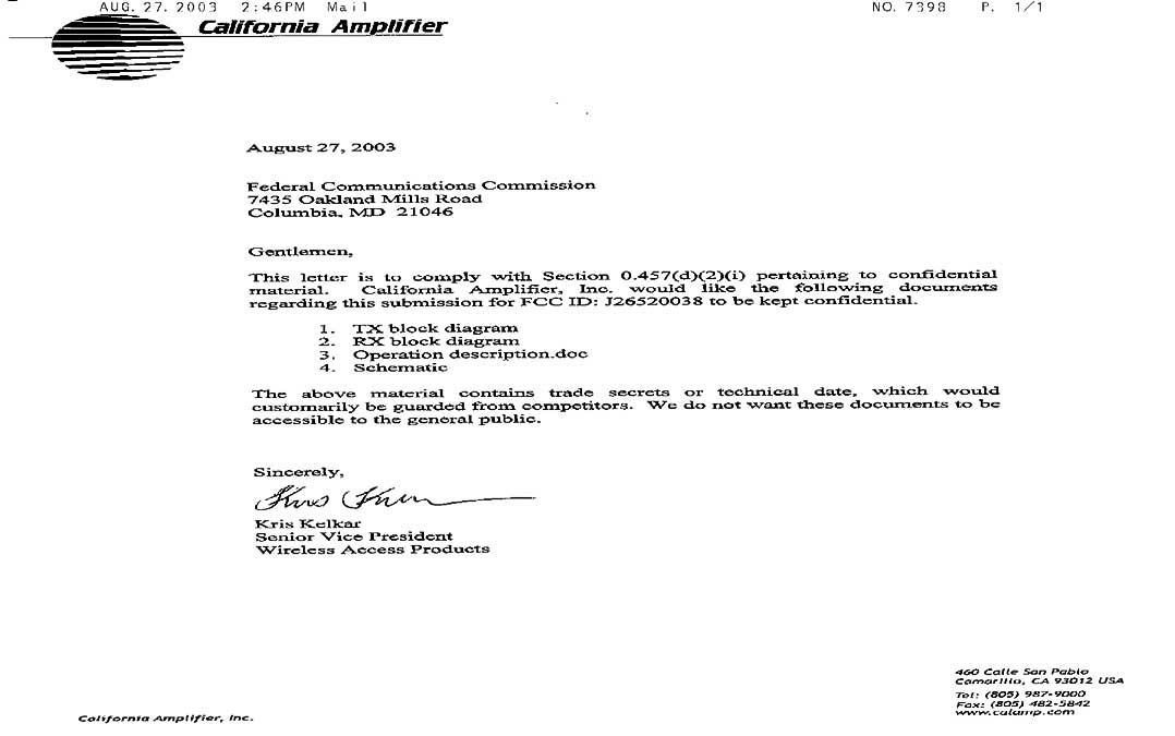
Cover Letter(s)
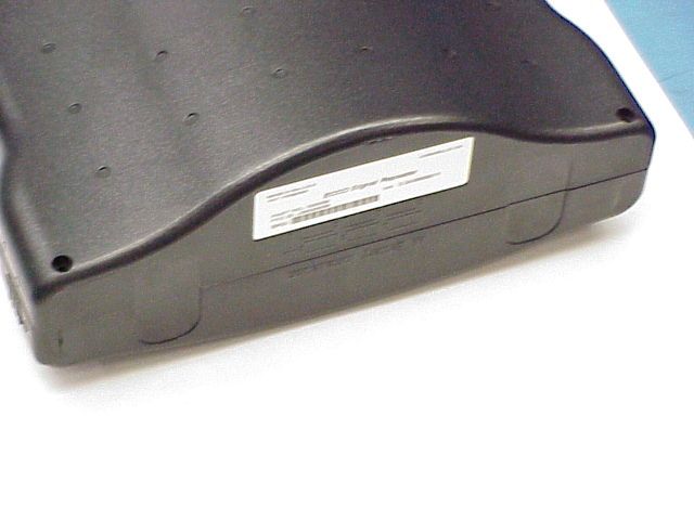
Submittal Photo Disclaimer: The interior photos are taken of the device used for testing. This device contains antenna connectors that are not part of the final product. The antenna connectors shown were provided by the customer for compliance testing purposes only.
Internal Photos
Interior Front Interior Front Close-up 1 Interior Front Close-up 2 Interior Front Close-up 3 Interior Front Close-up 4 Interior Front Close-up 5 Interior Front Close-up 6 Interior Front Without Shield Interior Back Interior Back Close-up 1 Interior Back Close-up 2 Interior Back Close-up 3 Interior Back Close-up 4 Interior Back Close-up 5 Interior Back Close-up 6 Interior Back Without Shield Interior Side 1 Interior Side 2
Internal Photos
Interior Front Interior Front Close-up 1 Interior Front Close-up 2 Interior Front Close-up 3 Interior Front Close-up 4 Interior Front Close-up 5 Interior Front Close-up 6 Interior Front Without Shield Interior Back Interior Back Close-up 1 Interior Back Close-up 2 Interior Back Close-up 3 Interior Back Close-up 4 Interior Back Close-up 5 Interior Back Close-up 6 Interior Back Without Shield Interior Side 1 Interior Side 2
Parts List/Tune Up Info
Response to E03-000078-3 FCC 2.1033(c)(9) TUNE-UP PROCEDURE Levels are factory set and the customer has no control over it.
Test Report
Page 1 of 95 Report No.: FC03-056 CALIFORNIA AMPLIFIER TEST REPORT FOR THE ECCO MUSTANG CELLULAR AMPLIFIER, 520038 FCC PART 24 COMPLIANCE DATE OF ISSUE: AUGUST 28, 2003 PREPARED FOR: California Amplifier 460 Calle San Pablo Camarillo, CA 93012 PREPARED BY: Mary Ellen Clayton CKC Laboratories, Inc. 5473A Clouds Rest Mariposa, CA 95338 P.O. No.:29582 W.O. No.:80997 Date of test:August 25-27, 2003 Report No.: FC03-056 This report contains a total of 95 pages and may be reproduced in full only. Partial reproduction may only be done with the written consent of CKC Laboratories, Inc. The results in this report apply only to the items tested, as identified herein. Page 2 of 95 Report No.: FC03-056 TABLE OF CONTENTS Administrative Information..............................................................................................3 Summary of Results.........................................................................................................4 Conditions for Compliance..............................................................................................4 Approvals.........................................................................................................................4 Equipment Under Test (EUT) Description......................................................................5 Equipment Under Test.....................................................................................................5 Peripheral Devices............................................................................................................5 Measurement Uncertainty................................................................................................5 Temperature and Humidity During Testing.....................................................................6 FCC 2.1033(c)(3) User’s Manual.....................................................................................6 FCC 2.1033(c)(4) Type of Emissions..............................................................................6 FCC 2.1033(c)(5) Frequency Range................................................................................6 FCC 2.1033(c)(6) Operating Power.................................................................................6 FCC 2.1033(c)(7) Maximum Power Rating.....................................................................6 FCC 2.1033(c)(8) DC Voltages.......................................................................................6 FCC 2.1033(c)(9) Tune-Up Procedure.............................................................................6 FCC 2.1033(c)(10) Schematics and Circuitry Description..............................................6 FCC 2.1033(c)(11) Label and Placement.........................................................................6 FCC 2.1033(c)(12) Submittal Photos...............................................................................6 FCC 2.1033(c)(13) Modulation Information...................................................................6 FCC 2.1033(c)(14)/2.1046/24.232 - RF Power Output...................................................7 FCC 2.1055(d)/24.235 Frequency Stability Under Voltage Variations...........................10 FCC 2.1033(c)(14)/2.1047(b) - Audio Frequency Response...........................................12 FCC 2.1033(c)(14)/2.1047(b) - Modulation Limiting Response.....................................12 FCC 2.1033(c)(14)/2.1049(i) - Occupied Bandwidth......................................................12 FCC 2.1033(c)(14)/2.1051/24.238 - Spurious Emissions at Antenna Terminal..............16 FCC 2.1051/2.1053 – Block Edge Plots..........................................................................31 FCC 2.1051/2.1053/24.238 - Intermodulation Attenuation Plots....................................56 FCC 2.1033(c)(14)/2.1053/24.238 - Field Strength of Spurious Radiation.....................81 FCC 2.1033(c)(14)/2.1055/24.235 - Frequency Stability................................................86 FCC 2.1091 - MPE Calculations......................................................................................86 Input and Output Plots.....................................................................................................87 Page 3 of 95 Report No.: FC03-056 ADMINISTRATIVE INFORMATION DATE OF TEST:August 25-27, 2003 DATE OF RECEIPT:August 25, 2003 PURPOSE OF TEST:To demonstrate the compliance of the Ecco Mustang Cellular Amplifier, 520038 with the requirements for FCC Part 24 devices. TEST METHOD:FCC Part 24 FREQUENCY RANGE TESTED:150 kHz - 1000 MHz MANUFACTURER:California Amplifier 460 Calle San Pablo Camarillo, CA 93012 REPRESENTATIVE:Shawn Aleman TEST LOCATION:CKC Laboratories, Inc. 5473A Clouds Rest Mariposa, CA 95338 Page 4 of 95 Report No.: FC03-056 SUMMARY OF RESULTS As received, the California Amplifier Bidirectional Amplifier, 520038 was found to be fully compliant with the following standards and specifications: United States ÿ FCC Part 24 CONDITIONS FOR COMPLIANCE No modifications to the EUT were necessary to comply. APPROVALS Steve Behm, Director of Engineering Services QUALITY ASSURANCE:TEST PERSONNEL: Joyce Walker, Quality Assurance Administrative Manager Randy Clark, EMC Engineer Mike Wilkinson, Lab Manager Page 5 of 95 Report No.: FC03-056 EQUIPMENT UNDER TEST (EUT) DESCRIPTION The EUT tested by CKC Laboratories was representative of a production unit EQUIPMENT UNDER TEST Bidirectional Amplifier Manuf: California Amplifier Model: 520038 Serial: 001 FCC ID: Pending PERIPHERAL DEVICES The EUT was tested with the following peripheral device(s): Power Divider Manuf: Anaren Model: 40276 Serial: 600D-7949 FCC ID: NA ESG Manuf: Agilent Model: E4437B Serial: US39260124 FCC ID: DoC ESG Manuf: Agilent Model: E4437B Serial: US39260294 FCC ID: DoC DC Power Supply Manuf: Topward Electric Instruments Co., Ltd. Model: TPS-2000 Serial: 920035 FCC ID: NA MEASUREMENT UNCERTAINTY TESTHIGHEST UNCERTAINTY Ra…
Text truncated - open the document above for the full version.
Test Report
Page 51 of 95 Report No.: FC03-056 BLOCK EDGE PLOT - UPSTREAM CDMA D LOW Page 52 of 95 Report No.: FC03-056 BLOCK EDGE PLOT - UPSTREAM CDMA E LOW Page 53 of 95 Report No.: FC03-056 BLOCK EDGE PLOT - UPSTREAM CDMA F HIGH Page 54 of 95 Report No.: FC03-056 BLOCK EDGE PLOT - UPSTREAM CDMA F LOW Test Equipment DescriptionAsset #ManufacturerModel #Serial #Cal DateCal Due Spectrum Analyzer, 9kHz to 26.5 GHz 02111HP8593EM3624A001595/12/035/11/05 Cable-HFP01403Semiflex58758-2300381/21/031/21/04 Page 55 of 95 Report No.: FC03-056 Direct Connect Page 56 of 95 Report No.: FC03-056 FCC 2.1051/2.1053/24.238 - INTERMODULATION ATTENUATION - DOWNSTREAM CDMA A Intermodulation Attenuation Test (3 Signal Method) Blocks Tested: A-F Upstream and Downstream Input Frequency Range: 1850-1910 MHz (Upstream) and 1930-1990 MHz (Downstream) Modulation Tested: CDMA (representative of worst case emissions) Frequency Range Tested: 20MHz to 20GHz RBW=1MHz and VBW=1MHz except in the 1MHz bandwidth outside of the assigned block where RBW=100kHz and VBW=1MHz Three input signals are chosen such that in the 15MHz channel blocks the lowest and highest channels are selected in addition to the third lowest channel. In the 5 MHz channel blocks the lowest and highest channels are selected in addition to the second lowest channel. Page 57 of 95 Report No.: FC03-056 INTERMODULATION ATTENUATION - DOWNSTREAM CDMA B Page 58 of 95 Report No.: FC03-056 INTERMODULATION ATTENUATION - DOWNSTREAM CDMA C Page 59 of 95 Report No.: FC03-056 INTERMODULATION ATTENUATION - DOWNSTREAM CDMA D Page 60 of 95 Report No.: FC03-056 INTERMODULATION ATTENUATION - DOWNSTREAM CDMA E Page 61 of 95 Report No.: FC03-056 INTERMODULATION ATTENUATION - DOWNSTREAM CDMA F Page 62 of 95 Report No.: FC03-056 INTERMODULATION ATTENUATION - DOWNSTREAM GSM A Page 63 of 95 Report No.: FC03-056 INTERMODULATION ATTENUATION - DOWNSTREAM GSM B Page 64 of 95 Report No.: FC03-056 INTERMODULATION ATTENUATION - DOWNSTREAM GSM C Page 65 of 95 Report No.: FC03-056 INTERMODULATION ATTENUATION - DOWNSTREAM GSM D Page 66 of 95 Report No.: FC03-056 INTERMODULATION ATTENUATION - DOWNSTREAM GSM E Page 67 of 95 Report No.: FC03-056 INTERMODULATION ATTENUATION - DOWNSTREAM GSM F Page 68 of 95 Report No.: FC03-056 INTERMODULATION ATTENUATION - UPSTREAM CDMA A Page 69 of 95 Report No.: FC03-056 INTERMODULATION ATTENUATION - UPSTREAM CDMA B Page 70 of 95 Report No.: FC03-056 INTERMODULATION ATTENUATION - UPSTREAM CDMA C Page 71 of 95 Report No.: FC03-056 INTERMODULATION ATTENUATION - UPSTREAM CDMA D Page 72 of 95 Report No.: FC03-056 INTERMODULATION ATTENUATION - UPSTREAM CDMA E Page 73 of 95 Report No.: FC03-056 INTERMODULATION ATTENUATION - UPSTREAM CDMA F Page 74 of 95 Report No.: FC03-056 INTERMODULATION ATTENUATION - UPSTREAM GSM A Page 75 of 95 Report No.: FC03-056 INTERMODULATION ATTENUATION - UPSTREAM GSM B Page 76 of 95 Report No.: FC03-056 INTERMODULATION ATTENUATION - UPSTREAM GSM C Page 77 of 95 Report No.: FC03-056 INTERMODULATION ATTENUATION - UPSTREAM GSM D Page 78 of 95 Report No.: FC03-056 INTERMODULATION ATTENUATION - UPSTREAM GSM E Page 79 of 95 Report No.: FC03-056 INTERMODULATION ATTENUATION - UPSTREAM GSM F Test Equipment DescriptionAsset #ManufacturerModel #Serial #Cal DateCal Due Spectrum Analyzer, 9kHz to 26.5 GHz 02111HP8593EM3624A001595/12/035/11/05 Cable-HFP01403Semiflex58758-2300381/21/031/21/04 Page 80 of 95 Report No.: FC03-056 Direct Connect Page 81 of 95 Report No.: FC03-056 FCC 2.1033(c)(14)/2.1053/24.238 - FIELD STRENGTH OF SPURIOUS RADIATION Test Conditions: Equipment is a bi-directional amplifier repeater for broadband PCS. The signal input is connected to the signal generators through a power divider. The output terminals of the transmitter are terminated into a resistive load. The amplifier is tested in two configurations in power representing the minimum and maximum power output. For the minimum power output, the input to the amplifier is terminated. For the maximum power output, the input to the amplifier is set such that the maximum power output is achieved at the customer supplied antenna connectors. Minimum Power Output is less than 10nW. Maximum Allowable Power Output is 19dBm. Intermodulation Attenuation Test (3 Signal Method) Blocks Tested: A-F Upstream and Downstream Input Frequency Range: 1850-1910 MHz (Upstream) and 1930-1990 MHz (Downstream) Modulation Tested: CDMA (representative of worst case emissions) Frequency Range Tested: 20MHz to 20GHz RBW=1MHz and VBW=1MHz except in the 1MHz bandwidth outside of the assigned block where RBW=100kHz and VBW=1MHz Three input signals are chosen such that in the 15MHz channel blocks the lowest and highest channels are selected in addition to the third lowest channel. In the 5 MHz channel blocks the lowest and highest channels are selected in addition to the second lowest channel. Page 82 of 95 Report No.: FC03-056 1850-1910 MHz Upstream and 1930-1990 MHz Downstream Low, middle and high For Blocks A, B, C, D, E & F 27.50ERP(dBm)=0.562EIRP(Watts) 3meters 43+10Log(P)=40.50dBc 4,522.43-35.00Vert62.50 4,537.35-34.70Vert62.20 1,494.93-32.70Vert60.20 1,522.50-32.20Horiz59.70 1,477.48-31.70Horiz59.20 1,487.48-31.10Vert58.60 1,512.43-31.10Vert58.60 1,487.55-30.60Horiz58.10 1,512.43-30.30Horiz57.80 1,507.48-29.40Horiz56.90 1,507.48-29.30Vert56.80 1,494.98-27.1Horiz54.60 Freq. (MHz)Reference Level (dBm)Antenna Polarity (H/V)dBc Operating Frequency: Limit: Distance: Highest Measured Output Power: Channels: 1,477.48-35.70Vert63.20 5,950.13-36.00Vert63.50 1,522.55-36.00Vert63.50 4,537.50-37.40Horiz64.90 4,484.88-38.00Vert65.50 5,979.80-38.00Vert65.50 4,462.43-38.30Horiz65.80 5,909.90-40.30Vert67.80 4,567.45-42.90Vert70.40 3,014.78-43.80Horiz71.30 3,014.95-44.10Vert71.60 4,567.60-45.60Horiz73.10 4,432.43-46.00Vert73.50 2,989.95-49.70Horiz77.20 Test Equipment: FunctionS/NCalibration DateCal Due DateAsset # HP 8593EM Spectrum Analyzer3624A0015905/12/200305/12/20052111 EMCO Loop Antenna207806/05/200206/05/2003432 Chase CB…
Text truncated - open the document above for the full version.
Test Report
Page 1 of 95 Report No.: FC03-056 CALIFORNIA AMPLIFIER TEST REPORT FOR THE ECCO MUSTANG CELLULAR AMPLIFIER, 520038 FCC PART 24 COMPLIANCE DATE OF ISSUE: AUGUST 28, 2003 PREPARED FOR: California Amplifier 460 Calle San Pablo Camarillo, CA 93012 PREPARED BY: Mary Ellen Clayton CKC Laboratories, Inc. 5473A Clouds Rest Mariposa, CA 95338 P.O. No.:29582 W.O. No.:80997 Date of test:August 25-27, 2003 Report No.: FC03-056 This report contains a total of 95 pages and may be reproduced in full only. Partial reproduction may only be done with the written consent of CKC Laboratories, Inc. The results in this report apply only to the items tested, as identified herein. Page 2 of 95 Report No.: FC03-056 TABLE OF CONTENTS Administrative Information..............................................................................................3 Summary of Results.........................................................................................................4 Conditions for Compliance..............................................................................................4 Approvals.........................................................................................................................4 Equipment Under Test (EUT) Description......................................................................5 Equipment Under Test.....................................................................................................5 Peripheral Devices..........................................…
Text truncated - open the document above for the full version.
Contact Information
Applicant
Steve Hall(Director of Technology)
Technical Contact
CKC LaboratoriesMary Ellen Clayton
[email protected]209 966-5240
5473-A Clouds Rest · Mariposa, California · United States
Non-Technical Contact
CKC LaboratoriesMary Ellen Clayton
[email protected]209 966-5240
Test Firm
CKC Laboratories, Inc.Steve Behm
Technical Specifications
| # | Rule Parts | Frequency Range | Power Output | Emission | Tolerance |
|---|---|---|---|---|---|
| 4 | 24 | 1.93 GHz - 1.99 GHz | 562.00 mW | GXW | Amp |
Other Applications from CalAmp Corp.

J26-4859300114
Feb 24, 2014LTE PCI-e Moudular
Equipment Class
JBP - Part 15 Class B Computing Device Peripheral
J26-PC-UC-2
May 16, 2012OSMAC Base Station
Equipment Class
TNB - Licensed Non-Broadcast Station Transmitter
J26500003
Mar 29, 2005CalAmp Corp. Directed AP
Equipment Class
DTS - Digital Transmission System
J26-530009
Mar 16, 2003MMDS Wireless Modem, 530009
Equipment Class
TNB - Licensed Non-Broadcast Station Transmitter
J26520031-2
Sep 30, 2001MMDS/MMDS Low TX In-Band Transceiver
Equipment Class
TNB - Licensed Non-Broadcast Station Transmitter