JQU-801154Compact RF Module, model 801154
KAPSCH TRAFFICCOM CANADA INC.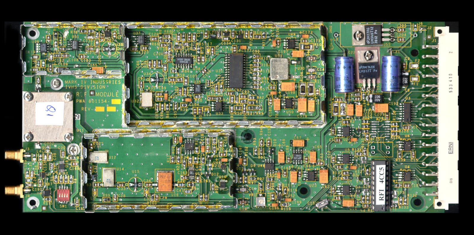
Click to zoom
Application Details
- Equipment Class
- LMS - Part 90 Location & Monitoring Transmitter
- Date of Grant
- Dec 09, 2002
- Application Purpose
- Original Equipment
- Date of Application
- Aug 27, 2002
- Equipment Note
- Compact RF Module, model 801154
- Frequency Range
- 915.75000000 - 915.75000000
- Country
- Canada
Documents & Files
Document Text
Text extracted from the exhibit documents filed with the FCC. Open a document above to read the original.
Users Manual
CR2000 Reader Installation Instructions Document A316000-775 2001 MARK IV INDUSTRIES LTD. Revision B, Issue printed on 12/4/2002 10:27 AM, filename: E:\Ready_To_Convert\Doc\287265.DOC CONFIDENTIAL: This document is the confidential property of Mark IV Industries Ltd. and may not be released or copied without written permission. CR2000 - Reader Kit CR2000 - Reader Kit Packing List Part Number Description 801075-001 CR2000 Compact Reader 318993-009 DC Power Pack, 110Vac input, output 5V/3A, 15V/1.5A, -15V/0.3A, Skynet #SNP-PA54 318145-177 CR2000 PC Software on Diskette 801076-001 Antenna Assembly CR2000 Reader - Connections CR2000 - Installation Tools Your tool kit should include (but is not limited to)... ♦ N-type connector crimp tool ♦ screwdrivers: flat blade, Philips blade ♦ SAE Socket set ♦ utility knife, wire cutter, wire stripper CR2000- Installation Items The kit of reader components described at left does not include the following required items... 1 PC cable, RS232 (DTE-DCE), 12 feet (see Fig 1) A/R antenna mount hardware: bracket(s), clamp(s), mast, etc. 100 feet (or less A/R) of RG213U cable 2.5 feet of RG58U cable 1 N-male connector for RG213U cable 1 N-female connector for RG213U cable 1 N-male connector for RG58U cable 1 N-female connector for RG58U cable 1 each of fixed attenuators: 1, 2, 3, 4, 5, 6, and 7 dB A/R heat shrink tubing, electrical tape, cable ties and clamps NOTE: During system installation, the contractor determines the fixed RF attenuation level required. CR2000- Installation Overview ♦ The antenna is installed within the distance/angular limits of the "pick-up point" as indicated in Table 1 on the back page ♦ The reader, power pack, antenna adapter cable and "total RF attenuation" components are installed at a location inside the building (see Figure 1 on the back page) that is (all of)... within 6 feet of a 110Vac power main drop within 12 feet (4 meters) of the host computer within 100 feet of the antenna mounting location outside the building ♦ All system connections are completed as indicated in the CR2000 - Installation Steps listed on the back page. ♦ The CR2000 PC application software is transferred from the diskette to the host computer and is running. ♦ The total RF attenuation value is determined by varying the configuration of the available fixed attenuators. NOTE: Where necessary, Mark IV Industries Ltd. I.V.H.S. personnel may be required to "fine tune" the system RF attenuation parameters. Document Revision Record Rev Date ECN Approved A 18-Jan-01 Preliminary power cable antenna adapter cable PC cable CR2000 reader antenna software diskette power pack CR2000 Reader Installation Instructions Document A316000-775 2001 MARK IV INDUSTRIES LTD. Revision B, Issue printed on 12/4/2002 10:27 AM, filename: E:\Ready_To_Convert\Doc\287265.DOC CONFIDENTIAL: This document is the confidential property of Mark IV Industries Ltd. and may not be released or copied without written permission. CR2000 - Antenna mounting The antenna will be mounted over-head at a height of Ha ft with horizontal polarization where Ha is measured from the highest part of the antenna. Determine the distance Do (in ft) between the "pick-up point" and the antenna mast, and use it to determine the antenna tilt down angle α° in the in-lane direction (H Plane), using the following table. Antenna Height (Ha) [ft] Pick-up Point (Do) * [ft] Antenna Tilt Angle (α) [Deg] Beam Center ** [ft] 12 5 to 7 15 3 7 to 9 18 4 12.5 5 to 7 15 3 7 to 9 18 4 13 6 to 8 15 3.5 8 to 10 18 4.5 13.5 7 to 9 15 4 9 to 10 18 4.5 * Distance referred to the antenna mast. ** Based on semi-empirical data. Note: This device shall cause no harm at a distance greater than 1 meter away from the antenna. The antenna has gain of 6 db. CR2000 - Installation Steps Connect the antenna with the reader via RF feedline and RF attenuator(s) and antenna adapter cable. 1) Disconnect the power main input to the power supply. 2) Connect the Power supply output to the CR2000 reader. 3) Connect the PC port COM1 to the reader host port using the provided straight through RS-232 cable. 4) Connect the RF cable adapter (RG58 short cable) to the reader RF port (Type N connector). 5) Connect the RF feedline to the RF cable adapter via the fixed attenuator(s) referenced in step 9. Install a Type-N Male connector at the end of the feedline. 6) Route the RF feedline through the wall. At the feedline antenna end, slip 6" of heatshrink tubing on the cable. Install a Type-N female connector at the end of the feedline. Make the connection with the antenna. 7) Reconnect the power main input to the power supply. 8) Execute the CR2000 PC application software as referenced in document A316000-743. 9) Determine the "total RF attenuation" value by varying the configuration of the available fixed attenuator value(s). 10) After the system has been fully tested OK then heat shrink the tubing (in step 6) over the antenna connector to make it water tight. Figure 1 - Installation Diagram attenuatorattenuator N male N male N female N male RF cable RG213U < 100 ft N female/female attenuator *** N male N male/female antenna RF cable RG58U < 2.5 ft CR2000 Reader N female N male/female DC power pack 110 Vac mains supply Host PC running CR2000-PC software DB9 female Host port (P2) DB9 female* DCE DB9 male DB9 male* RS232 cable #22AWG, 3 conductor > 6 ft < 40 ft (12 ft default or specify) Optional: RS485 cable #22AWG, 5 conductor > 40 ft < 200 ft (always specify) DTE vehicle with a transponder "RF capture zone" when RF is turned on outside the building inside the building ***total RF attenuation" value is determined at the end of the installation process antenna adapter cable antenna feedline cable "total RF attenuation" value *Please verify the serial port connector type on your host PC, is it DB9 or DB25? PC cable
Users Manual
CR2000 Reader Installation Instructions Document A316000-775 2001 MARK IV INDUSTRIES LTD. Revision B, Issue printed on 12/6/2002 1:46 PM, filename: E:\Ready_To_Convert\Doc\288040.DOC CONFIDENTIAL: This document is the confidential property of Mark IV Industries Ltd. and may not be released or copied without written permission. CR2000 - Reader Kit CR2000 - Reader Kit Packing List Part Number Description 801075-001 CR2000 Compact Reader 318993-009 DC Power Pack, 110Vac input, output 5V/3A, 15V/1.5A, -15V/0.3A, Skynet #SNP-PA54 318145-177 CR2000 PC Software on Diskette 801076-001 Antenna Assembly CR2000 Reader - Connections CR2000 - Installation Tools Your tool kit should include (but is not limited to)... ♦ N-type connector crimp tool ♦ screwdrivers: flat blade, Philips blade ♦ SAE Socket set ♦ utility knife, wire cutter, wire stripper CR2000- Installation Items The kit of reader components described at left does not include the following required items... 1 PC cable, RS232 (DTE-DCE), 12 feet (see Fig 1) A/R antenna mount hardware: bracket(s), clamp(s), mast, etc. 100 feet (or less A/R) of RG213U cable 2.5 feet of RG58U cable 1 N-male connector for RG213U cable 1 N-female connector for RG213U cable 1 N-male connector for RG58U cable 1 N-female connector for RG58U cable 1 each of fixed attenuators: 1, 2, 3, 4, 5, 6, and 7 dB A/R heat shrink tubing, electrical tape, cable ties and clamps NOTE: During system installation, the contractor determines the fixed RF attenuation level required. CR2000- Installation Overview ♦ The antenna is installed within the distance/angular limits of the "pick-up point" as indicated in Table 1 on the back page ♦ The reader, power pack, antenna adapter cable and "total RF attenuation" components are installed at a location inside the building (see Figure 1 on the back page) that is (all of)... within 6 feet of a 110Vac power main drop within 12 feet (4 meters) of the host computer within 100 feet of the antenna mounting location outside the building ♦ All system connections are completed as indicated in the CR2000 - Installation Steps listed on the back page. ♦ The CR2000 PC application software is transferred from the diskette to the host computer and is running. ♦ The total RF attenuation value is determined by varying the configuration of the available fixed attenuators. NOTE: Where necessary, Mark IV Industries Ltd. I.V.H.S. personnel may be required to "fine tune" the system RF attenuation parameters. Document Revision Record Rev Date ECN Approved A 18-Jan-01 Preliminary power cable antenna adapter cable PC cable CR2000 reader antenna software diskette power pack CR2000 Reader Installation Instructions Document A316000-775 2001 MARK IV INDUSTRIES LTD. Revision B, Issue printed on 12/6/2002 1:46 PM, filename: E:\Ready_To_Convert\Doc\288040.DOC CONFIDENTIAL: This document is the confidential property of Mark IV Industries Ltd. and may not be released or copied without written permission. CR2000 - Antenna mounting The antenna will be mounted over-head at a height of Ha ft with horizontal polarization where Ha is measured from the highest part of the antenna. Determine the distance Do (in ft) between the "pick-up point" and the antenna mast, and use it to determine the antenna tilt down angle α° in the in-lane direction (H Plane), using the following table. Antenna Height (Ha) [ft] Pick-up Point (Do) * [ft] Antenna Tilt Angle (α) [Deg] Beam Center ** [ft] 12 5 to 7 15 3 7 to 9 18 4 12.5 5 to 7 15 3 7 to 9 18 4 13 6 to 8 15 3.5 8 to 10 18 4.5 13.5 7 to 9 15 4 9 to 10 18 4.5 * Distance referred to the antenna mast. ** Based on semi-empirical data. Note: User must maintain a separation distance of 23cm from the antenna. The antenna has gain of 6 db. CR2000 - Installation Steps Connect the antenna with the reader via RF feedline and RF attenuator(s) and antenna adapter cable. 1) Disconnect the power main input to the power supply. 2) Connect the Power supply output to the CR2000 reader. 3) Connect the PC port COM1 to the reader host port using the provided straight through RS-232 cable. 4) Connect the RF cable adapter (RG58 short cable) to the reader RF port (Type N connector). 5) Connect the RF feedline to the RF cable adapter via the fixed attenuator(s) referenced in step 9. Install a Type-N Male connector at the end of the feedline. 6) Route the RF feedline through the wall. At the feedline antenna end, slip 6" of heatshrink tubing on the cable. Install a Type-N female connector at the end of the feedline. Make the connection with the antenna. 7) Reconnect the power main input to the power supply. 8) Execute the CR2000 PC application software as referenced in document A316000-743. 9) Determine the "total RF attenuation" value by varying the configuration of the available fixed attenuator value(s). 10) After the system has been fully tested OK then heat shrink the tubing (in step 6) over the antenna connector to make it water tight. Figure 1 - Installation Diagram attenuatorattenuator N male N male N female N male RF cable RG213U < 100 ft N female/female attenuator *** N male N male/female antenna RF cable RG58U < 2.5 ft CR2000 Reader N female N male/female DC power pack 110 Vac mains supply Host PC running CR2000-PC software DB9 female Host port (P2) DB9 female* DCE DB9 male DB9 male* RS232 cable #22AWG, 3 conductor > 6 ft < 40 ft (12 ft default or specify) Optional: RS485 cable #22AWG, 5 conductor > 40 ft < 200 ft (always specify) DTE vehicle with a transponder "RF capture zone" when RF is turned on outside the building inside the building ***total RF attenuation" value is determined at the end of the installation process antenna adapter cable antenna feedline cable "total RF attenuation" value *Please verify the serial port connector type on your host PC, is it DB9 or DB25? PC cable
Cover Letter(s)
Offices in Ottawa (Canada), USA, Norway, England, Germany, Italy, Korea, Taiwan, China and Shanghai August 28, 2002 Federal Communications Commission Equipment Authorization Branch 7435 Oakland Mills Road Columbia, Maryland 21046 USA Nemko Canada Inc. 303 River Road RR #5 Ottawa, Ontario Canada K1V 1H2 Tel: 613-737-9680 Fax: 613-737-9691 Toll Free: 1-800-563-6336 Email: [email protected] Internet: www.nemkoca.com Dear Sir/Madam:Our File Ref. 2W06277 FCC ID: JQU-801154 Applicant: Mark IV Industries IVHS Division Equipment: Compact RF Module, model 801154 FCC Confirmation no.: EA We have successfully electronically filed all the required documentation for an application for certification in accordance with FCC Part 90 on the above mentioned equipment. If you require additional information, please do not hesitate to contact me at 1-800-563-6336 (extension 232). Thank you in advance for your assistance in this matter. Sincerely, Ruby Dulmage Submissions Specialist Nemko Canada Inc. [email protected] Encl.
Cover Letter(s)
Re: FCC ID: JQU-801154 FCC Correspondence Number: 24131 Applicant: Mark IV Industries 731 Confirmation no.: EA662659 Below are the answers to your questions: Thank you for correcting the equipment code and rule part on the 731 form. 1. As described in the CR2000 Reader Installation Instructions the antenna height is 12 feet and the minimum distance for safety requirement as per calculations is 23 centimeters. The installation will be performed by qualified personnel. A statement will be added to the manual to say that "this device will cause no harm at a distance greater than 1 meter away from the antenna, also the antenna will have gain of 6 dB." 2. The design description document for compact RF Module page 4 describes the specification for this device. This is an LMS device operating at a fixed frequency of 915.75 MHZ. The specification page should be as follows Nominal Frequency 915.75 MHZ Frequency stability 2.5 ppm Nominal power port 1 0.631 watts Nominal power port 2 0.63 miliwatts Spurious and harmonics <-25 dbm 3. This is a fixed frequency device operating at 915.75 MHZ. 4. The signal substitution method was used as per TIA/EIA-603 (please see the sig. sub. conversion factor column on page 15 of report as well as set up diagram on page 21 of report). The maximized average power level was reproduced by replacing the EUT with a substitution antenna and a signal generator using a CW tone.
Cover Letter(s)
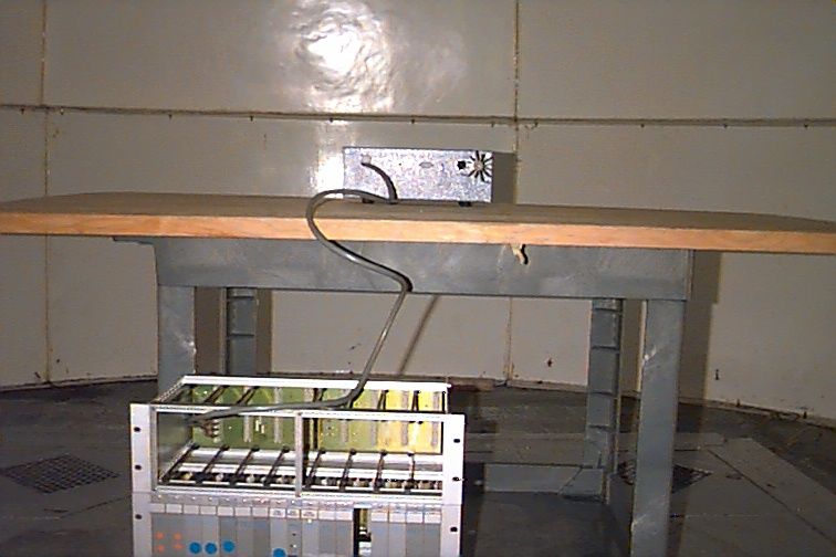
Re: FCC ID: JQU-801154 Applicant: Mark IV Industries Ltd. Correspondence Reference no.: 24347 731 Confirmation no.: EA662659 1. An exhibit has been uploaded with the radiated emissions test data showing the signal substitution factor and also a test setup photo. 2. The emission designator need to be changed to 12M1K1D. Which is 12 MHZ bandwidth,Modulation AM (Manchester encoded ON/Off Keying),frequency band 902-928 (K),data (D). The modulation scheme used is Manchester Encoded ON/OFF Keying. This is single frequency operation unit (915.75 MHZ).The data frequency is 500 KHZ. The unit meets the sidebands requirements in the bandwidth of 909.75-921.75 MHZ as per part 90. So THE Bandwidth required is 12 MHZ.There are two modes of operation as described in the design description, 3. The user manual shows the box,antenna,power supply and software.The box contains the current production RF Module FCC ID: JQU-800495 which is also used in the Road Check Reader system in the toll collection,digital board and attenuators. This new FCC ID: JQU-801154 will replace the JQU-800495 RF module in the Mgate reader application. This new unit was designed to reduce the system cost. For the ease of test and qualification this unit can be tested with our current reader. So the user manual will be modified to have the new unit replacing the old unit. The old RF Module (JQU-800495) is an enclosed unit with covers on both sides and rf connectors at the side of the housing.This unit has shields for the sensitive parts of the circuit. 4.The user manual will be modified to include the statement about the RF exposure " This device shall cause no harm at a distance greater than 1 meter away from the antenna". The CR2000 Reader Installation instructions shows that the antenna is mounted 12 feet high above the ground so the RF exposure is minimal.
ID Label/Location Info
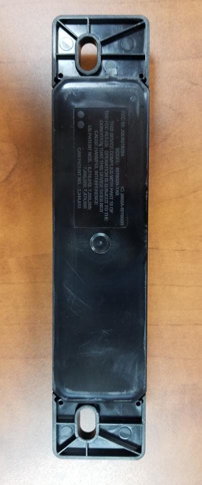
DESCRIPTION EXCEPT AS MAY BE OTHERWISE PROVIDED BY CONTRACT, THESE DRAWINGS AND SPECIFICATIONS CONTAIN PROPRIETARY INFORMATION AND ARE THE PROPERTY OF MARK IV INDUSTRIES LIMITED I.V.H.S. DIVISION AND ARE ISSUED IN STRICT CONFIDENCE AND SHALL NOT BE TRANSMITTED REPRODUCED OR COPIED OR USED AS THE BASIS FOR MANUFACTURE OR SALE APPARATUS WITHOUT PRIOR WRITTEN PERMISSION. MARK IV INDUSTRIES LTD. I.V.H.S. DIVISION ISO CERTIFICATION No. 002002 IVEN013 REV C UNLESS OTHERWISE SPECIFIED, DIMENSIONS ARE IN INCHES, DIMENSIONAL LIMITS AND SURFACE ROUGHNESS DESIGNATIONS APPLY BEFORE PROTECTIVE FINISHES ARE APPLIED. SEE NOTES FOR SURFACE FINISHES AND TOLERANCES ON FRACTIONS, DECIMALS AND ANGLES. C APPROVED ENGRG CHECKED D.O. SCALE DATE DATE DATE DATE A SIZE DRAWNDATE APPLICATION NEXT ASSEMBLYUSED ONLTR TAB No. I.V.H.S. DIVISION DRAWING No. MISSISSAUGA, ONTARIO, CANADA FILE No.SHEET MARK IV INDUSTRIES LTD. REVISIONS DATEAPPROVED PROPOSED FCC LABEL, COMPACT RF MODULE N/AFCC1 of 1 A ORIGINAL ISSUE -------------- 2002
RF Exposure Info
Exposure of Humans to RF Fields Analysis Performed By: Glen WestwellDate of Test: 21 Aug 2002 Maximum Permissible Exposure (MPE) Compliance Statement, FCC Radio Frequency Exposure Limit 1.1310 & Industry Canada RSS-102 Mark IV 801154 Radio Module The 801154 Radio Module has been tested and the performance characterized in accordance with the MPE requirements of FCC 47 CFR and Industry Canada RSS-102. At an operating frequency of 915.75MHz the MPE limit for the General Population/Uncontrolled Exposure is 0.61mW/cm 2 (f/1500mW/cm 2 ). This device complies with this limit at the following line of sight distances from the antenna element: 801154 Radio Module: 23cm The analysis is provided below. Power Density (S) = EIRP/(4πR 2 ), Therefore, R≥√EIRP/S x 4π Using this calculation: Maximum Antenna Gain = 8dBi Maximum output power = 28dBm S = 0.6 mW/cm 2 EIRP = 36dBm or 4W(max. worst case) Therefore, R= 22.8 cm This minimum safe distance for the general population of 23cm shall be stated in the installation & operators instruction manual under the RF Safety Exposure Warning Statement. Analysis provided by, Glen Westwell, Nemko Canada Inc. for Mark IV Industries.
Test Report
Master: PT90PLMT Date: February 25, 2001 Test Report:2W06277 Applicant:Mark IV Industries 6020 Ambler Drive Mississauga, Ontario L4W 2P1 Equipment Under Test:Mark IV “RF Module” (EUT)915.75MHz FCC ID: In Accordance With:FCC Part 90, Subpart M 902-928MHz, LMS Systems Tested By:Nemko Canada Inc. 303 River Road, R.R. 5 Ottawa, Ontario K1V 1H2 Authorized By: J. Harrington, RF Group Manager Date:28 August 2002 Total Number of Pages:21 Nemko Canada Inc.FCC PART 90 Sub Part M, LMS Systems PROJECT NO.:2W06277 Mark IV 801154 Radio Module Page 2 of 21 Table of Contents Section 1. Summary of Test Results......................................................................................3 Section 2. General Equipment Specification........................................................................5 Section 3. RF Power Output..................................................................................................6 Section 4. Occupied Bandwidth...........................................................................................7 Section 9. Field Strength of Spurious Emissions................................................................11 Section 10.Frequency Stability..............................................................................................17 Section 12. Test Equipment List...........................................................................................18 Section 13.Test Diagrams......................................................................................................19 Nemko Canada Inc.FCC PART 90 Sub Part M, LMS Systems PROJECT NO.:2W06277 Mark IV 801154 Radio Module Page 3 of 21 Section 1.Summary of Test Results General All measurements are traceable to national standards. These tests were conducted on a sample of the equipment for the purpose of demonstrating compliance with FCC Part 90, Sub part M. New SubmissionProduction Unit Class II Permissive ChangePre-Production Unit TNB Equipment Code THIS TEST REPORT RELATES ONLY TO THE ITEM(S) TESTED. THE FOLLOWING DEVIATIONS FROM, ADDITIONS TO, OR EXCLUSIONS FROM THE TEST SPECIFICATIONS HAVE BEEN MADE. See “ Summary of Test Data”. TESTED BY: _____________________________________ DATE: 26 August 2002 Glen Westwell, Wireless Technologist Nemko Canada Inc. authorizes the above named company to reproduce this report provided it is reproduced in its entirety and for use by the company’s employees only. Any use which a third party makes of this report, or any reliance on or decisions to be made based on it, are the responsibility of such third parties. Nemko Canada Inc. accepts no responsibility for damages, if any, suffered by any third party as a result of decisions made or actions based on this report. This report applies only to the items tested. Nemko Canada Inc.FCC PART 90 Sub Part M, LMS Systems PROJECT NO.:2W06277 Mark IV 801154 Radio Module Page 4 of 21 Summary Of Test Data Name Of TestPara. No.Result RF Power Output2.1046Complies Occupied Bandwidth2.1049Complies Spurious Emissions at Antenna Terminals 2.1051Complies Field Strength of Spurious Emissions2.1053Complies Frequency Stability2.1055Complies Notes: This Radio Module device is used in the 909.75-921.75MHz (12MHz) band for non- multilateration LMS operations. IndoorTemperature:22°C Humidity:40% OutdoorTemperature:26°C Humidity:48% . Nemko Canada Inc.FCC PART 90 Sub Part M, LMS Systems PROJECT NO.:2W06277 EQUIPMENT: Mark IV 801154 Radio Module Page 5 of 21 Section 2.General Equipment Specification Manufacturer: Mark IV Industries Model No.: 801154 Serial No.: JQU-801154 Q1 Date Received In Laboratory: 24 July 2002 Nemko Identification No.: #13 Frequency Range: 902-928MHz Transmit Frequency: 915.75MHz (fixed) RF Power Output: Authorized Bandwidth: 0.631W 12MHz Emission Designator: 12M0P0D Nemko Canada Inc.FCC PART 90 Sub Part M, LMS Systems PROJECT NO.:2W06277 EQUIPMENT: Mark IV 801154 Radio Module Page 6 of 21 Section 3.RF Power Output Para. No.: 2.1046 Test Performed By: Glen WestwellDate of Test: 21 Aug 2002 Minimum Standard:90.205 Test Results:Complies. The RF power output is 27.3dBm (0.54)W. This is within +/- 1dB of the manufacturers rating of 28.0dBm. Measurement Data:0.54W (27.3dBm) Nemko Canada Inc.FCC PART 90 Sub Part M, LMS Systems PROJECT NO.:2W06277 EQUIPMENT: Mark IV 801154 Radio Module Page 7 of 21 Section 4.Occupied Bandwidth Para. No.: 2.1049 Test Performed By: Glen WestwellDate of Test: 21 Aug 2002 Minimum Standard:90.210 Test Results:Complies Measurement Data:See Attached Plots. Nemko Canada Inc.FCC PART 90 Sub Part M, LMS Systems PROJECT NO.:2W06277 EQUIPMENT: Mark IV 801154 Radio Module Page 8 of 21 Nemko Canada Inc.FCC PART 90 Sub Part M, LMS Systems PROJECT NO.:2W06277 EQUIPMENT: Mark IV 801154 Radio Module Page 9 of 21 Section 5.Spurious Emissions at Antenna Terminals Para. No.: 2.1051 Test Performed By: Glen WestwellDate of Test: 21 Aug 2002 Minimum Standard:90.210, -25dBm Test Results:Complies. Measurement Data:See Attached Plot. Nemko Canada Inc.FCC PART 90 Sub Part M, LMS Systems PROJECT NO.:2W06277 EQUIPMENT: Mark IV 801154 Radio Module Page 10 of 21 Nemko Canada Inc.FCC PART 90 Sub Part M, LMS Systems PROJECT NO.:2W06277 EQUIPMENT: Mark IV 801154 Radio Module Page 11 of 21 Section 9.Field Strength of Spurious Emissions Para. No.: 2.1053 Test Performed By: Glen WestwellDate of Test: 22 Aug 2002 Minimum Standard:90.210, -25dBm Test Results:Complies. Measurement Data:See Attached Table. Duty Cycle Correction Factor:-20dB TX power on time:20uS + (39.6uS x 0.31v) = 32.3uS Duty Cycle/100mS:60 x 32.3uS = 1.9mS Therefore: 20Log (1.9mS/100mS) = -34.4dB Nemko Canada Inc.FCC PART 90 Sub Part M, LMS Systems PROJECT NO.:2W06277 EQUIPMENT: Mark IV 801154 Radio Module Page 12 of 21 Nemko Canada Inc.FCC PART 90 Sub Part M, LMS Systems PROJECT NO.:2W06277 EQUIPMENT: Mark IV 801154 Radio Module Page 13 of 21 Nemko Canada Inc.FCC PART 90 Sub Part M, LMS Systems PROJECT NO.:2W06277 EQUIPMENT: Mark IV 801154 Radio Module …
Text truncated - open the document above for the full version.
Test Report
Signal Substitution Date: November 22, 2002 Tester: Dome # A Distance: 3 m Location: Glen Westwell 8564E Comment : Mark IV Retest JQU-801154 Temp: Humidity: Antenna Polarity RCVD Signal (dBuV) Ant. Factor (dB) Sig. Sub. Factor Amp. Gain (dB) Duty Cycle Corr. Cable Loss (dB) Field Str. (dBm) Limit (dBm) Margin (dB) Horn1 V 87.5 -119.1 3.8 -27.8 -25.0 2.8 Horn1 H 89.2 -119.7 3.8 -26.7 -25.0 1.7 Horn1 V 96.5 -127.5 5.5 -25.5 -25.0 0.5 Horn1 H 98.0 -129.1 5.5 -25.5 -25.0 0.5 Horn1 V 81.2 -124.8 6.0 -37.6 -25.0 12.6 Horn1 H 79.2 -126.3 6.0 -41.1 -25.0 16.1 Horn1 V 75.8 -120.7 7.3 -37.6 -25.0 12.6 Horn1 H 71.3 -121.2 7.3 -42.6 -25.0 17.6 Horn1 V 70.3 -117.7 8.3 -39.1 -25.0 14.1 Horn1 H 66.0 -114.9 8.3 -40.6 -25.0 15.6 Horn1 V 84.7 -120.0 9.5 -25.8 -25.0 0.8 Horn1 H 81.0 -117.4 9.5 -26.9 -25.0 1.9 Horn1 V 71.8 -116.0 11.9 -32.4 -25.0 7.4 Horn1 H 74.5 -116.7 11.9 -30.3 -25.0 5.3
Test Report
Signal Substitution: ANSI/TIA/EIA-603-1992, Radiated Spur. Emissions, Para.2.2.12 Date: November 22, 2002 Tester: Dome # A Distance: 3 m Location Glen Westwell 8564E Comment: Mark IV Retest JQU-801154 Temp: Humidity: Frequency Anten na Polarity RCVD Signal (dBuV) Ant. Factor (dB) Sig. Sub. Factor Amp. Gain (dB) Duty Cycle Corr. Cable Loss (dB) Field Str. (dBm) Limit (dBm) Margin (dB) 1831.5000 Horn1 V 87.5 -119.1 3.8 -27.8 -25.0 2.8 1831.5000 Horn1 H 89.2 -119.7 3.8 -26.7 -25.0 1.7 2747.2000 Horn1 V 96.5 -127.5 5.5 -25.5 -25.0 0.5 2747.2000 Horn1 H 98.0 -129.1 5.5 -25.5 -25.0 0.5 3662.9000 Horn1 V 81.2 -124.8 6.0 -37.6 -25.0 12.6 3662.9000 Horn1 H 79.2 -126.3 6.0 -41.1 -25.0 16.1 4578.7000 Horn1 V 75.8 -120.7 7.3 -37.6 -25.0 12.6 4578.7000 Horn1 H 71.3 -121.2 7.3 -42.6 -25.0 17.6 5494.5000 Horn1 V 70.3 -117.7 8.3 -39.1 -25.0 14.1 5494.4000 Horn1 H 66.0 -114.9 8.3 -40.6 -25.0 15.6 6410.2000 Horn1 V 84.7 -120.0 9.5 -25.8 -25.0 0.8 6410.2000 Horn1 H 81.0 -117.4 9.5 -26.9 -25.0 1.9 7325.9000 Horn1 V 71.8 -116.0 11.9 -32.4 -25.0 7.4 7325.9000 Horn1 H 74.5 -116.7 11.9 -30.3 -25.0 5.3
Contact Information
Applicant
Alastair Malarky(Chief Engineer)
Technical Contact
Non-Technical Contact
Nemko Canada Inc.Ruby Dulmage
[email protected]613-737-9680
Test Firm
Nemko Canada Inc.Stuart Beck
Technical Specifications
| # | Rule Parts | Frequency Range | Power Output | Emission | Tolerance |
|---|---|---|---|---|---|
| 1 | 90.353 | 915.75 MHz - 915.75 MHz | 631.00 mW | 525KF1D | 1.0300000000 ppm |
Other Applications from KAPSCH TRAFFICCOM CANADA INC.
JQU801800C
Sep 13, 2023Non-multilateration LMS Transponder
Equipment Class
LMS - Part 90 Location & Monitoring Transmitter
JQU802870
Apr 19, 2021Non-multilateration LMS Tranceiver
Equipment Class
LMS - Part 90 Location & Monitoring Transmitter
JQU801660C
Jan 27, 2020LMS Interior Transponder
Equipment Class
LMS - Part 90 Location & Monitoring Transmitter
JQU802295AA
Sep 16, 2015Non-multilateral LMS transmitter and receiver
Equipment Class
LMS - Part 90 Location & Monitoring Transmitter
JQU802477
Jun 15, 2014TRP-8100
Equipment Class
LMS - Part 90 Location & Monitoring Transmitter