JQU801660CLMS Interior Transponder
KAPSCH TRAFFICCOM CANADA INC.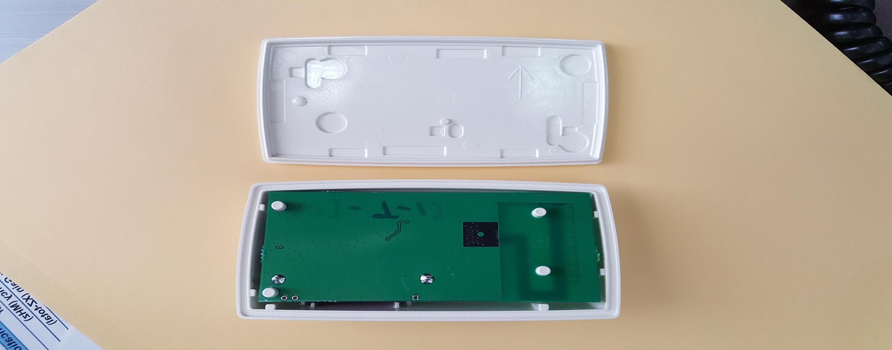
Click to zoom
Application Details
- Equipment Class
- LMS - Part 90 Location & Monitoring Transmitter
- Date of Grant
- Jan 27, 2020
- Application Purpose
- Original Equipment
- Date of Application
- Jan 23, 2020
- Equipment Note
- LMS Interior Transponder
- Frequency Range
- 915.00000000 - 915.00000000
- Country
- Canada
Documents & Files
Document Text
Text extracted from the exhibit documents filed with the FCC. Open a document above to read the original.
Users Manual
Kapsch TrafficCom Janus™ Interior Transponder Mounting Instructions For Passenger Vehicles Janus interior transponders mount to the inside of the vehicle windshield using 3M™ Dual Lock™ fasteners. Arrows on the transponder provide the correct mounting orientation. Requirements > For reliable operation of the transponder, the vehicle should not be equipped with more than one transponder of similar design while passing through a toll facility. Other transponders present in or on the vehicle must be switched off or enclosed in an RF shield. > The mounting location must provide direct line-of-sight communication between the transponder and the toll facility overhead antenna. > Do not mount the interior transponder in vehicles: > with non-metallic roofs. > with windshields covered in RF-blocking material (ex. metal oxide). > with a metallic center windshield dividing post. > without center-mounted rear view mirrors. > Handheld mobile communication devices must not be located within 12” (30 cm) of the transponder. > Metal objects (except for the rear view mirror and the roof) must not be located within 6” (15 cm) of the transponder. > Interior transponders cannot be used where local regulations prohibit mounting transponders on the windshield. EN Transponder Mounting Instructions Choose the appropriate mounting location of the transponder (preferred or alternative) before affixing it to the windshield using the provided 3M™ Dual Lock™ reclosable fasteners. Preferably the transponder should be mounted between the roofline and the rear view mirror mounting post, such that the top of the transponder is ½” (1¼ cm), but no more than 2” (5 cm) from the roofline, and the bottom of the transponder is a minimum of ½” (1¼ cm) from the rear view mirror post. If the transponder cannot be mounted in the preferred mounting location, mount it within the alternative mounting area shown below: 1. Select the appropriate mounting location for the transponder. 2. Prepare the area on the windshield where the transponder will be mounted in accordance with 3M™ document 70-0709-4029-4. 3. Remove the protective backing from the two 3M™ Dual Lock™ reclosable fasteners and press the transponder into place, ensuring the orientation arrows are pointing upwards. 4. Firmly press the transponder against the windshield and maintain pressure on the transponder for approximately 15 seconds to ensure a good bond to the windshield. 5. To remove the transponder from the windshield, lift any corner with sufficient force to separate the Dual Lock™ reclosable fastener strips. Do not reuse the 3M™ Dual Lock™ reclosable fasteners strips if removing them from the windshield. Obtain new strips as required. FCC License Notice – This device complies with Part 15 of the FCC rules. Operation is subject to the condition that this device does not cause harmful interferences. Kapsch TrafficCom is a provider of intelligent transportation systems in the fields of tolling, traffic management, smart urban mobility, traffic safety and security, and connected vehicles. As a one-stop solutions provider, Kapsch TrafficCom offers end-to-end solutions covering the entire value creation chain of its customers, from components and design to the implementation and operation of systems. The mobility solutions supplied by Kapsch TrafficCom help make road traffic safer and more reliable, efficient, and comfortable in urban areas and on highways alike. >>> www.kapsch.net 801850 - 008 R ev E _EN - US © Kapsch TrafficCom AG. All rights reserved. Contents subject to change without notice. Alternative Mounting Location Preferred Mounting Location – Front View Transponder – Rear View Preferred Mounting Location – Side View
Users Manual
© 2020 Kapsch TrafficCom Canada Inc., all rights reserved. Kapsch TrafficCom Info Number 801660C Application Author Alastair Malarky Date 2020 01 03 JANUS™ Interior OBU – 801660C-TAB User Manual References: FCC ID: JQU801660C IC: 2665A-801660C The only manual/instructions provided to end user are the mounting instructions. There are no user modifiable features in the product. The mounting instructions differ by vehicle type. The instructions are attached as Appendix 1. The instructions also contain the FCC notice required by Part 15: FCC License Notice - This device complies with part 15 of the FCC rules. Operation is subject to the condition that this device does not cause harmful interference.
External Photos
© 2020 Kapsch TrafficCom Canada Inc., all rights reserved. Kapsch TrafficCom Info Number 801660C Application Author Alastair Malarky Date 2020 01 03 JANUS™ Interior OBU – 801660C-TAB – External Photographs References: FCC ID: JQU801660C IC: 2665A-801660C 801660C Label and Location 801660C-TAB Top View © 2020 Kapsch TrafficCom Canada Inc., all rights reserved. Kapsch TrafficCom 801660C–TAB Bottom View 801660C–TAB Long Side View © 2020 Kapsch TrafficCom Canada Inc., all rights reserved. Kapsch TrafficCom 801660C–TAB Short Side View
ID Label/Location Info
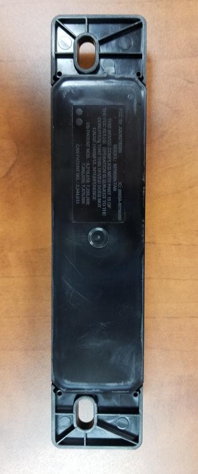
© 2020 Kapsch TrafficCom Canada Inc., all rights reserved. Kapsch TrafficCom Info Number 801660C Application Author Alastair Malarky Date 2020 01 03 To TUV SUD Canada Inc JANUS™ Interior OBU – 801660C-TAB Label and Location References: FCC ID: JQU801660C IC: 2665A-801660C The following defines the label and the location of the label for the model 801660C-TAB. Due to the need to place other jurisdiction regulatory permanent labels on the certain models, it is not considered practical to place the information required by 47 CFR Part 15 on those models such that it is readable. Therefore in accordance with 47 CFR 15.19 (5) for those models the statement required by Part 15 is provided in the mounting instructions that are to be supplied to the user, a copy of which is included in this application. Label Size For model 801660C-TAB the permanent label is 2.3 (wide) x 1.65 (high) inches on the back of the unit. © 2020 Kapsch TrafficCom Canada Inc., all rights reserved. Kapsch TrafficCom Label Location The label is located on the rear of each unit and is engraved into the unit. The unit rear is shown in the following picture. Rear view of Model 801660C-TAB Note the picture does not show the final version of the permanent label text – this is shown in the next section. Permanent Label Adhesive Adhesive © 2020 Kapsch TrafficCom Canada Inc., all rights reserved. Kapsch TrafficCom Rear view of Model 801660C-TAB Labelling area
Internal Photos
© 2020 Kapsch TrafficCom Canada Inc., all rights reserved. These drawings and specifications contain confidential and proprietary information and are the property of Kapsch TrafficCom Canada Inc. and are issued in strict confidence and will be kept confidential and used solely for the purpose intended and for no other purpose and shall not be transmitted, reproduced, copied, and/or used as the basis for manufacture or sale of apparatus unless otherwise agreed to in writing by Kapsch TrafficCom Canada Inc. . Kapsch TrafficCom Info Number 801660C Application Author Alastair Malarky Date 2020 01 03 To TUV SUD JANUS™ Interior OBU – 801660C-TAB Label and Location References: FCC ID: JQU801660C IC: 2665A-801660C The internal photographs of the model tested are shown below. PWA Rear Photo – Model 801660C-TAB © 2020 Kapsch TrafficCom Canada Inc., all rights reserved. These drawings and specifications contain confidential and proprietary information and are the property of Kapsch TrafficCom Canada Inc. and are issued in strict confidence and will be kept confidential and used solely for the purpose intended and for no other purpose and shall not be transmitted, reproduced, copied, and/or used as the basis for manufacture or sale of apparatus unless otherwise agreed to in writing by Kapsch TrafficCom Canada Inc. . Kapsch TrafficCom PWA Front Photo – Model 801660C-TAB © 2020 Kapsch TrafficCom Canada Inc., all rights reserved. These drawings and specifications contain confidential and proprietary information and are the property of Kapsch TrafficCom Canada Inc. and are issued in strict confidence and will be kept confidential and used solely for the purpose intended and for no other purpose and shall not be transmitted, reproduced, copied, and/or used as the basis for manufacture or sale of apparatus unless otherwise agreed to in writing by Kapsch TrafficCom Canada Inc. . Kapsch TrafficCom Model 801660C-TAB in a case
RF Exposure Info
Report File #: 7169006761R-000 © TÜV SÜD Canada Inc. This test report shall not be reproduced except in full, without written approval of TÜV SÜD Canada Inc Exhibit: RF Exposure – FCC Client Kapsch TrafficCom Canada Inc. Product JANUS TM Interior OBU Model: 801660C-TAB Standard(s) FCC KDB 447498:2015 Page 2 of 2 Report Issued: 12/2/2019 Report File #: 7169006761R-000 © TÜV SÜD Canada Inc. This test report shall not be reproduced except in full, without written approval of TÜV SÜD Canada Inc. RF Exposure – FCC The device have no specified usage distance. The device is evaluated against Portable and Mobile usage conditions; it is evaluated against the smallest separation distance and against the tightest limit for SAR exemption and for MPE limit. General SAR test exclusion guidance: As per FCC KDB 447498 Section 4.3.1 a), the 1-g SAR Test Exclusion Threshold for 100 MHz to 6 GHz at test separation distances ≤ 50 mm is determined by: [(max. power of channel, including tune-up tolerance, mW)/(min. test separation distance, mm)] [√f (GHz) ] ≤ 3.0 Where: f (GHz) is the RF channel transmit frequency in GHz SAR Calculations: 915 MHz transmitter Peak conducted power was measured to be 0.5 mW. At a separation distance of 5 mm, this results to: [0.5 mW / 5 mm]*[√0.915 GHz] = 0.1 ≤ 3.0 SAR Exclusion Threshold condition is met with peak conducted power.
Test Report
Registration # 6844A-3 Testing Laboratory Certificate #2955.02 R-4023, G-506 C-4498, T-1246 Registration # CA6844 Page 1 of 37 Report Issued: 1/14/2020 Report File #:7169006761R -000 © TÜV SÜD Canada Inc. This test report shall not be reproduced except in full, without written approval of TÜV SÜD Canada Inc FCC 15 247 Rev2 RF Test Report As per RSS-137 Issue 2:2009 & FCC Part 90 Subpart M Location and Monitoring Service (LMS) Operation in the 902 -928 MHz Band on the JANUS TM Interior OBU Model: 801660C-TAB Issued by: TÜV SÜD Canada Inc. 11 Gordon Collins Dr, Gormley, ON, L0H 1G0 Canada Ph: (905) 883-7255 Testing produced for See Appendix A for full client & EUT details. Prepared by Min Xie, Sr. EMC Engineer Reviewed by Amir Emami, Project Engineer Client Kapsch TrafficCom Canada Inc Product JANUS TM Interior OBU Model: 801660C-TAB Standard(s) RSS 137 Issue 2:2009 FCC Part 90 Subpart M Page 2 of 37 Report Issued: 1/14/2020 Report File #: 7169006761R-000 © TÜV SÜD Canada Inc. This test report shall not be reproduced except in full, without written approval of TÜV SÜD Canada Inc Table of Contents Table of Contents ................................................................................................................... 2 Report Scope .......................................................................................................................... 3 Summary ................................................................................................................................ 4 Test Results Summary ....................................................................................................... 5 Notes, Justifications, or Deviations ................................................................................... 6 Sample Calculation(s) ........................................................................................................ 7 Applicable Standards, Specifications and Methods ............................................................... 8 Document Revision Status ..................................................................................................... 9 Definitions and Acronyms ................................................................................................... 10 Testing Facility .................................................................................................................... 11 Calibrations and Accreditations ....................................................................................... 11 Testing Environmental Conditions and Dates ................................................................. 12 Detailed Test Results Section .............................................................................................. 13 Output Power and Antenna Heights ................................................................................ 14 Occupied Bandwidth ........................................................................................................ 17 Emission Mask ................................................................................................................. 20 Transmitter Spurious Radiated Emissions ....................................................................... 24 Temperature Frequency Stability ..................................................................................... 33 Appendix A – EUT Summary .............................................................................................. 35 Client Kapsch TrafficCom Canada Inc Product JANUS TM Interior OBU Model: 801660C-TAB Standard(s) RSS 137 Issue 2:2009 FCC Part 90 Subpart M Page 3 of 37 Report Issued: 1/14/2020 Report File #: 7169006761R-000 © TÜV SÜD Canada Inc. This test report shall not be reproduced except in full, without written approval of TÜV SÜD Canada Inc Report Scope This report addresses the EMC verification testing and test results of the Kapsch TrafficCom Canada Inc.’s JANUS TM INTERIOR OBU, Model: 801660C-TAB, and is herein referred to as EUT (Equipment Under Test). The EUT was tested for compliance against the following standards: RSS-137 Issue 2:2009 FCC Part 90 Subpart M Test procedures, results, justifications, and engineering considerations, if any, follow later in this report. The results contained in this report relate only to the item(s) tested. This report does not imply product endorsement by any government, accreditation agency, or TÜV SÜD Canada Inc. Opinions or interpretations expressed in this report, if any, are outside the scope of TÜV SÜD Canada Inc. accreditations. Any opinions expressed do not necessarily reflect the opinions of TÜV SÜD Canada Inc., unless otherwise stated. Client Kapsch TrafficCom Canada Inc Product JANUS TM Interior OBU Model: 801660C-TAB Standard(s) RSS 137 Issue 2:2009 FCC Part 90 Subpart M Page 4 of 37 Report Issued: 1/14/2020 Report File #: 7169006761R-000 © TÜV SÜD Canada Inc. This test report shall not be reproduced except in full, without written approval of TÜV SÜD Canada Inc Summary The results contained in this report relate only to the item(s) tested. EUT: JANUS TM INTERIOR OBU, Model: 801660C-TAB FCC Certification #, FCC ID: JQU801660C ISED Canada Certification #, IC: 2665A-801660C EUT passed all tests performed Yes Tests conducted by Min Xie For testing dates, see "Testing Environmental Conditions and Dates". Client Kapsch TrafficCom Canada Inc Product JANUS TM Interior OBU Model: 801660C-TAB Standard(s) RSS 137 Issue 2:2009 FCC Part 90 Subpart M Page 5 of 37 Report Issued: 1/14/2020 Report File #: 7169006761R-000 © TÜV SÜD Canada Inc. This test report shall not be reproduced except in full, without written approval of TÜV SÜD Canada Inc Test Results Summary Standard/Method Description Limit Result FCC 90.205 RSS-137 Clause 6.4 Output Power 30 W Pass FCC 90.207 RSS-137 Clause 6.2 Types of Modulation -- Pass See Justifications FCC 90.209 RSS-137 Clause 6.1.2 Occupied Bandwidth 902 - 904 MHz: 2 MHz 909.75 – 921.75 M…
Text truncated - open the document above for the full version.
Test Setup Photos
Report File #: 7169006761R-000 © TÜV SÜD Canada Inc. This test report shall not be reproduced except in full, without written approval of TÜV SÜD Canada Inc Exhibit: Test Setup Photos Client Kapsch TrafficCom Canada Inc. Product TRP-8100; Model:802477A-TAB Standard(s) RSS 137 Issue 2 FCC Part 90 Subpart M Page 2 of 4 Report Issued: 12/2/2019 Report File #: 7169006761R-000 © TÜV SÜD Canada Inc. This test report shall not be reproduced except in full, without written approval of TÜV SÜD Canada Inc. Figure 1 ‒ Radiated Emissions Setup – Photo 1 Client Kapsch TrafficCom Canada Inc. Product TRP-8100; Model:802477A-TAB Standard(s) RSS 137 Issue 2 FCC Part 90 Subpart M Page 3 of 4 Report Issued: 12/2/2019 Report File #: 7169006761R-000 © TÜV SÜD Canada Inc. This test report shall not be reproduced except in full, without written approval of TÜV SÜD Canada Inc. Figure 2 ‒ Radiated Emissions Setup – Photo 2 Client Kapsch TrafficCom Canada Inc. Product TRP-8100; Model:802477A-TAB Standard(s) RSS 137 Issue 2 FCC Part 90 Subpart M Page 4 of 4 Report Issued: 12/2/2019 Report File #: 7169006761R-000 © TÜV SÜD Canada Inc. This test report shall not be reproduced except in full, without written approval of TÜV SÜD Canada Inc. Figure 3 ‒ Antenna Port Conducted Emissions Setup
Contact Information
Applicant
Alastair Malarky(Chief Engineer)
Test Firm
TUV SUD CANADA (Gormley)William (Mac) Elliott
[email protected]813-284-2736
Technical Specifications
| # | Rule Parts | Frequency Range | Power Output | Emission | Tolerance |
|---|---|---|---|---|---|
| 1 | 90.353 | 915 MHz - 915 MHz | 900.00 µW | 3M28K1D | 114.0000000000 ppm |
Other Applications from KAPSCH TRAFFICCOM CANADA INC.
JQU801800C
Sep 13, 2023Non-multilateration LMS Transponder
Equipment Class
LMS - Part 90 Location & Monitoring Transmitter
JQU802870
Apr 19, 2021Non-multilateration LMS Tranceiver
Equipment Class
LMS - Part 90 Location & Monitoring Transmitter
JQU802295AA
Sep 16, 2015Non-multilateral LMS transmitter and receiver
Equipment Class
LMS - Part 90 Location & Monitoring Transmitter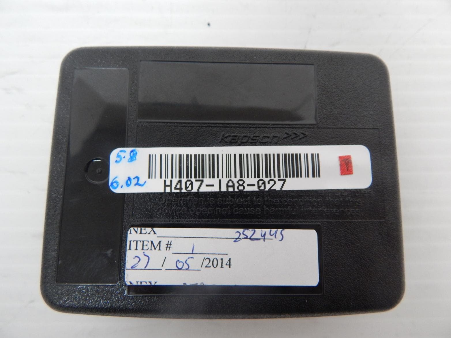
JQU802477
Jun 15, 2014TRP-8100
Equipment Class
LMS - Part 90 Location & Monitoring Transmitter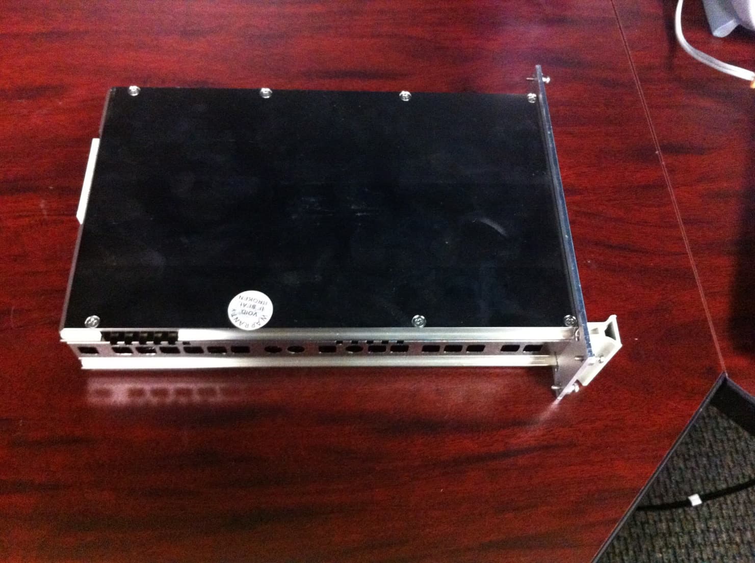
JQU802295A
May 11, 2014Non-multilateration LMS transmitter and receiver
Equipment Class
LMS - Part 90 Location & Monitoring Transmitter