JQU801090FPT 2000 Transponder
KAPSCH TRAFFICCOM CANADA INC.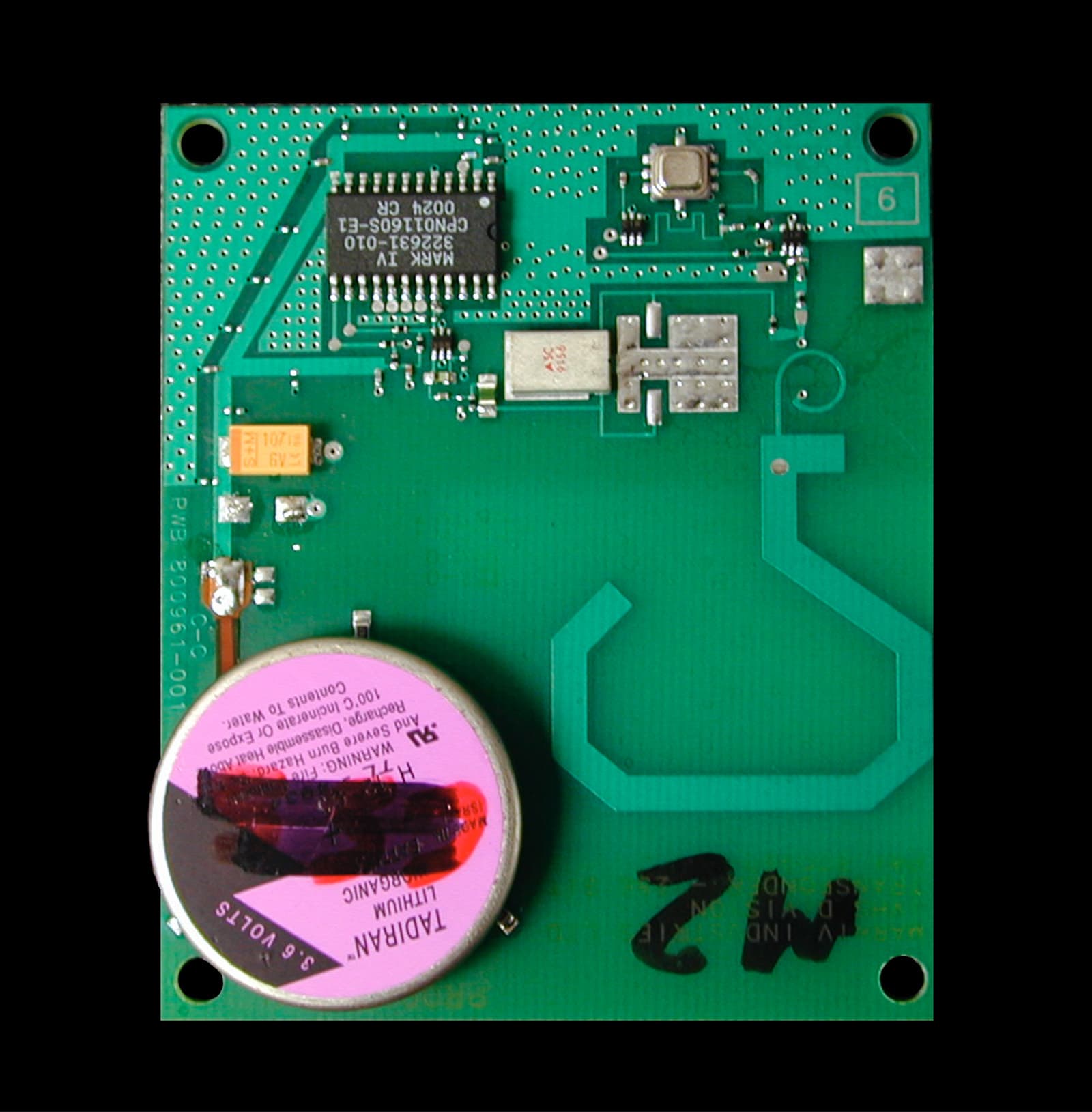
Click to zoom
Application Details
- Equipment Class
- LMS - Part 90 Location & Monitoring Transmitter
- Date of Grant
- Dec 22, 2003
- Application Purpose
- Original Equipment
- Date of Application
- Mar 01, 2001
- Equipment Note
- FPT 2000 Transponder
- Frequency Range
- 915.00000000 - 915.00000000
- Country
- Canada
Documents & Files
Document Text
Text extracted from the exhibit documents filed with the FCC. Open a document above to read the original.
ID Label/Location Info
I.V.H.S. DIVISION MISSISSAUGA, ONTARIO, CANADA MARK IV INDUSTRIES LTD.
Operational Description
Page 1 FLAT PACK TRANSPONDER FPT 2000 TECHNICAL DESCRIPTION Mark IV Industries 2 FEBRUARY 2001 Page 2 1. INTRODUCTION 1.1 Related documents Transponder drawing 800960 1.2 Definitions, Acronyms, Abbreviations Tx:Transmitter Rx:Receiver OOK:On-Off-Keying RF:Radio Frequency MOD:Modulator BPF:Bandpass Filter IAG:type of protocol (Inter Agency Group) OSC:Oscillator 1.3 System Operation Figure 1 is a block diagram of a typical automatic vehicle monitoring system. The three main components are the Flat Pack Transponder, Reader , Reader Antenna and RF modules. The Flat Pack Transponder is mounted on a vehicle’s windshield at a location visible to the Reader antenna. The directivity of the Reader antenna provides a defined capture zone. Up to 8 antennas can be serviced by a single Reader via the RF modules. Co-Axial cable to antenna READER ELECTRONICS RF MODULERF MODULERF MODULERF MODULERF MODULE RF MODULE RF MODULERF MODULE TRANSPONDER Communication Ports to Host Computers 120 VAC Reader Antenna Mounted on vehicle windshield FIGURE 1 Page 3 The Reader/RF modules are FCC Part 90 compliant and are typically mounted beside the roadway in a cabinet. The RF modules are connected to the antennas by means of co-axial cables. Transponder installation instructions are provided in Attachment A. In operation, the Reader via a selected RF module sends out a 915 MHz data stream in the format described below to each antenna in turn thereby establishing an intermittent RF field in each lane of the roadway. When a vehicle equipped with a transponder enters the field the pulses activate the transponder and cause it to respond with a data transmission on a carrier frequency of 915 MHz. It should be noted that the transponder is only activated when a 20 microsecond “wake-up” pulse is received. It will not radiate energy at any other time. Transponder radiation will be obscured by the stronger Reader RF field. The Transponder Tx data is received by the antenna which passes it to the RF module for detection and then to the Reader for decoding. If the Reader determines that re-programming of the transponder is necessary, the Reader sends an additional pulse stream to the transponder for that purpose. When the above process is completed on a given lane , it is repeated in the next lane and so on until as many lanes as necessary up to the full 8 lanes have been scanned. The timing for this process which shows RF activity for one lane is depicted in Figure 2. During a typical passage of a vehicle through a lane the transponder is typically read and programmed twice to confirm accuracy of the data and its CRC. Page 4 Figure 2 - System Timing Diagram READ CYCLE 20μsec20μsec Reader 100 μsec Transponder 512 μsec 512 μsec Minimum time = 6.4 msec to next cycle Transponder responds to each trigger pulse by transmitting a 512 microsecond Manchester encoded RF burst (500 kbit/second data rate) WRITE CYCLE 20 μsec20 μsec Reader 512 μsec 100μsec100μsec Transponder 512 μsec512 μsec Minimum time = 8.0 msec to next write cycle Transponder responds to each trigger pulse by transmitting a 512 microsecond Manchester encoded RF burst (500 kbit/second data rate) Page 5 1.4 Transponder Overview The Transponder consists of two major components: the case and a circuit board. The Transponder transmits and receives Manchester encoded data streams in the 915 MHZ frequency band. On-Off Keying modulation is used. There are five major electronic subsystems on the circuit board: 1. The “hook” Antenna which receives and transmits RF energy 2. The RF Transmitter has two sub-sections. An RF Oscillator that is turned on by the ASIC during the entire time the Transponder transmits. The modulator which converts the baseband Manchester encoded data delivered from the ASIC to the 915 MHz band using OOK (On-Off Keying) data stream. 3. The Receiver which demodulates the 915MHz band RF pulses received from the reader via the antenna. 4. The ASIC which provides: Rx, Tx data and control interfaces, Manchester encoding/decoding, CRC generation/detection. The control interfaces keep the transponder circuitry in low current (“idle mode”) until a trigger pulse of between 10 and 30 microseconds is detected. The ASIC transmits a Manchester encoded 256 frame at 500 kilobits per second when a valid trigger pulse is detected. The ASIC only stores the incoming bit stream if the CRC is correct. 5. The Battery which provides 3.60 volt power to operate the transponder. Page 6 2. Specifications ModulationOn-Off Keying of a Manchester encoded data stream Nominal Tx Frequency:915 MHz Peak Tx RF power-10 to -2 dBm Modulation Depth>25 dB Tx Side bands and -25 dBm Harmonics Data Rate:500 ± 15 kilobits per second Power3.6VDCLithium Battery Page 7 3. Block Diagram of the Transponder 4. Transmitter The transponder transmits the data stream to the reader after receiving the 20μsec trigger pulse from the reader (IAG protocol),. This generates an OOK modulated signal centered at 915 MHz. The RF output power from the transponder is between -7 to -2 dBm. 4.1 General Description The transmitter consists of an oscillator and modulator. The oscillator generates the CW signal at 915 MHz. The RF signal is modulated by the modulator stage which provides OOK modulation and amplification of the RF signal. The output of the modulator is connected to the antenna. TRANSMITTER BLOCK DIAGRAM DET & VIDAMPOSCMOD ANT BRF ASIC Tx Rx OSCMOD to Antenna Data Input Page 8 4.2 Detailed description 4.2.1 Oscillator The oscillator consists of a SAW resonator and RF amplifier and its associated circuitry. The SAW resonator provides the frequency stability of the oscillator. The output of the oscillator is RF continuous wave signal with center frequency of 915MHz. Circuit Components: U2, U4, C2, C3, C4,R2. 4.2.2 Modulator and filter The Modulator receives the RF continuous wave signal from the oscillator. It amplifies and modulates the signal using the On-Off keying modulation. The output nominal frequency is at …
Text truncated - open the document above for the full version.
Parts List/Tune Up Info
MARK IV INDUSTRIES LTD. I.V.H.S. DIVISION MISSISSAUGA, ONTARIO, CANADA I.V.H.S. DIVISION MARK IV INDUSTRIES LTD. I.V.H.S. DIVISION MISSISSAUGA, ONTARIO, CANADA I.V.H.S. DIVISION MARK IV INDUSTRIES LTD. I.V.H.S. DIVISION MISSISSAUGA, ONTARIO, CANADA I.V.H.S. DIVISION MARK IV INDUSTRIES LTD. I.V.H.S. DIVISION MISSISSAUGA, ONTARIO, CANADA I.V.H.S. DIVISION MARK IV INDUSTRIES LTD. I.V.H.S. DIVISION MISSISSAUGA, ONTARIO, CANADA I.V.H.S. DIVISION MARK IV INDUSTRIES LTD. I.V.H.S. DIVISION MISSISSAUGA, ONTARIO, CANADA I.V.H.S. DIVISION
Test Report
Master: ktlPT90PLMT Date: August 16, 2000 KTL Test Report:1R03567 Applicant:Mark IV Industries 6020 Ambler Drive Mississauga, Ontario L4W 2P1 Equipment Under Test:FPT 2000 Transponder (E.U.T.) FCC ID:JQU801090 In Accordance With:FCC Part 90 Tested By:KTL Ottawa Inc. 3325 River Road, R.R. 5 Ottawa, Ontario K1V 1H2 Authorized By: G. Westwell, Technologist Date: Total Number of Pages:15 KTL Ottawa FCC PART 90 PRIVATE LAND MOBILE TRANSMITTER PROJECT NO.: 1R03567 EQUIPMENT: FPT 2000 Transponder FCC ID: JQU801090 Page 2 of 15 Table of Contents Section 1. Summary of Test Results.......................................................................................... 3 Section 2. General Equipment Specification ........................................................................... 5 Section 3. RF Power Output .....................................................................................................6 Section 4. Occupied Bandwidth................................................................................................ 7 Section 5. Field Strength of Spurious Emissions................................................................... 10 Section 6. Test Equipment List ............................................................................................... 14 Section 7. Test Diagrams ......................................................................................................... 15 KTL Ottawa FCC PART 90 PRIVATE LAND MOBILE TRANSMITTER PROJECT NO.: 1R03567 EQUIPMENT: FPT 2000 Transponder FCC ID: JQU801090 Page 3 of 15 Section 1.Summary of Test Results General All measurements are traceable to national standards. These tests were conducted on a sample of the equipment for the purpose of demonstrating compliance with FCC Part 90. New SubmissionProduction Unit Class II Permissive ChangePre-Production Unit LMS Equipment Code THIS TEST REPORT RELATES ONLY TO THE ITEM(S) TESTED. THE FOLLOWING DEVIATIONS FROM, ADDITIONS TO, OR EXCLUSIONS FROM THE TEST SPECIFICATIONS HAVE BEEN MADE. See “ Summary of Test Data”. NVLAP LAB CODE: 100351-0 TESTED BY: _____________________________________ DATE: ___________________ Russell Grant, Wireless Group Manager KTL Ottawa Inc. authorizes the above named company to reproduce this report provided it is reproduced in its entirety and for use by the company’s employees only. Any us e whic h a third p a rty ma k e s o f this re p o rt, o r a ny re lia nc e o n o r d e c is io ns to b e ma d e b a s e d o n it, a re the re s p o ns ib ility of such third parties. KTL Ottawa Inc. accepts no responsibility fo r d a ma ge s , if a ny, s uffe re d b y a ny third p a rty a s a re s ult o f d e c is io ns ma d e o r a c tio ns b a s e d o n this re p o rt. This report applies only to the items tested. KTL Ottawa FCC PART 90 PRIVATE LAND MOBILE TRANSMITTER PROJECT NO.: 1R03567 EQUIPMENT: FPT 2000 Transponder FCC ID: JQU801090 Page 4 of 15 Summary Of Test Data Name Of TestPara. No.Result RF Power Output2.1046Complies Audio Frequency Response2.1047N/A (1) Audio Low-Pass Filter Response2.1047N/A (1) Modulation Limiting2.1047N/A (1) Occupied Bandwidth2.1049Complies Spurious Emissions at Antenna Terminals 2.1051N/A (2) Field Strength of Spurious Emissions2.1053Complies Frequency Stability2.1055N/A (3) Transient Frequency Behavior——N/A (4) Footnotes For N/A’s: (1) No voice processing. (2) This equipment uses an integral antenna. See Radiated Emissions measurement data. (3) Non-Multilateration Transponder. (4) Fixed 915MHz. . KTL Ottawa FCC PART 90 PRIVATE LAND MOBILE TRANSMITTER PROJECT NO.: 1R03567 EQUIPMENT: FPT 2000 Transponder FCC ID: JQU801090 Page 5 of 15 Section 2.General Equipment Specification Frequency Range: 915 MHz Fixed Primary Power: 3.6V Lithium Battery Modulation: Pulse Width Emission Designator: 6M0P1D 6M0P0D Rated RF Output Power: -9dBm Antenna: Integral Antenna This equipment uses RFM SAW or EPCOS SAW and MURATA Rx Filter or EPCOS Rx Filter. Measurements were made using both types of SAW and Rx Filter. KTL Ottawa FCC PART 90 PRIVATE LAND MOBILE TRANSMITTER PROJECT NO.: 1R03567 EQUIPMENT: FPT 2000 Transponder FCC ID: JQU801090 Page 6 of 15 Section 3.RF Power Output Para. No.: 2.1046 Test Performed By: Russell Grant Date of Test: February 21, 2001 Minimum Standard: N/A Test Results: Complies. Measurement Data: -9.5 dBm KTL Ottawa FCC PART 90 PRIVATE LAND MOBILE TRANSMITTER PROJECT NO.: 1R03567 EQUIPMENT: FPT 2000 Transponder FCC ID: JQU801090 Page 7 of 15 Section 4.Occupied Bandwidth Para. No.: 2.1049 Test Performed By: Russell Grant Date of Test: February 21, 2001 Minimum Standard: Emission Mask (k)(3) Test Results: Complies. Measurement Data: See attached graphs. KTL Ottawa FCC PART 90 PRIVATE LAND MOBILE TRANSMITTER PROJECT NO.: 1R03567 EQUIPMENT: FPT 2000 Transponder FCC ID: JQU801090 Page 8 of 15 KTL Ottawa FCC PART 90 PRIVATE LAND MOBILE TRANSMITTER PROJECT NO.: 1R03567 EQUIPMENT: FPT 2000 Transponder FCC ID: JQU801090 Page 9 of 15 KTL Ottawa FCC PART 90 PRIVATE LAND MOBILE TRANSMITTER PROJECT NO.: 1R03567 EQUIPMENT: FPT 2000 Transponder FCC ID: JQU801090 Page 10 of 15 Section 5.Field Strength of Spurious Emissions Para. No.: 2.1053 Test Performed By: Russell Grant Date of Test: February 21, 2001 Minimum Standard: Emission Mask (k)(3) Test Results: Complies. Measurement Data: The strongest emission is –30.1dBm at 2745MHz. This is 5.1dB below the specification limit. KTL Ottawa FCC PART 90 PRIVATE LAND MOBILE TRANSMITTER PROJECT NO.: 1R03567 EQUIPMENT: FPT 2000 Transponder FCC ID: JQU801090 Page 11 of 15 RFM SAW MURATA RX Filter Frequency of Emission (MHz)Polarization Received Signal (dBuV) Conversion Factor (dBuV to dBm) Emission Level (dBm) Limit (dBm) Margin (dB) 915V52.3-64.9-12.6 915H57.7-67.2-9.5 1830V86.0-117.5-31.5-25.06.5 1830H84.0-117.0-33.0-25.08.0 2745V88.0-124.4-36.4-25.011.4 2745H92.0-122.1-30.1-25.05.1 3660V75.0-117.7-42.7-25.017.7 3660H70.0-120.0-50.0-25.025.0 4575V69.0-114.1-45.1-25.020.1 4575H62.0-112.6-50.6-25.0…
Text truncated - open the document above for the full version.
Contact Information
Applicant
Alastair Malarky(Chief Engineer)
Technical Contact
Non-Technical Contact
KTL Ottawa Inc.Ruby C Dulmage
[email protected]800-563-6336
Test Firm
Nemko Canada Inc.Stuart Beck
Technical Specifications
| # | Rule Parts | Frequency Range | Power Output | Emission |
|---|---|---|---|---|
| 2 | 90.353 | 915 MHz - 915 MHz | 126.00 µW | 6M0P0D |
Other Applications from KAPSCH TRAFFICCOM CANADA INC.
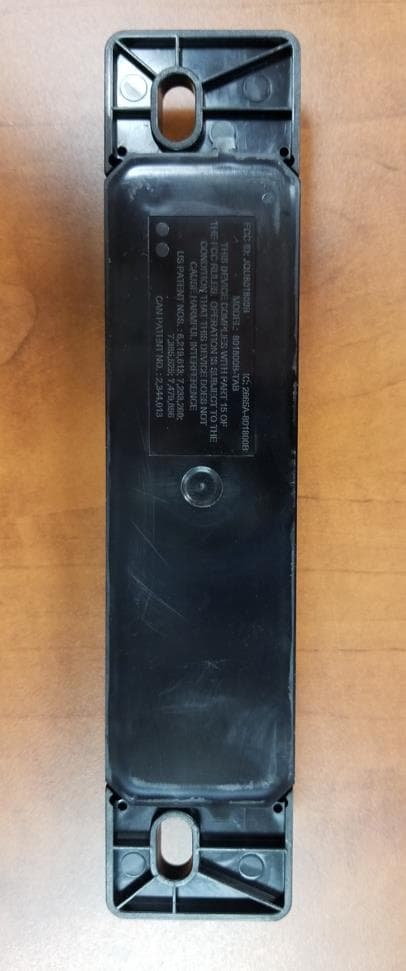
JQU801800C
Sep 13, 2023Non-multilateration LMS Transponder
Equipment Class
LMS - Part 90 Location & Monitoring Transmitter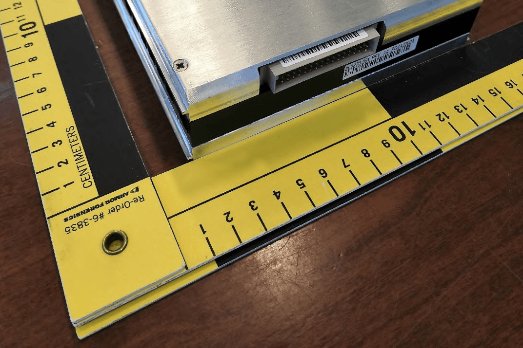
JQU802870
Apr 19, 2021Non-multilateration LMS Tranceiver
Equipment Class
LMS - Part 90 Location & Monitoring Transmitter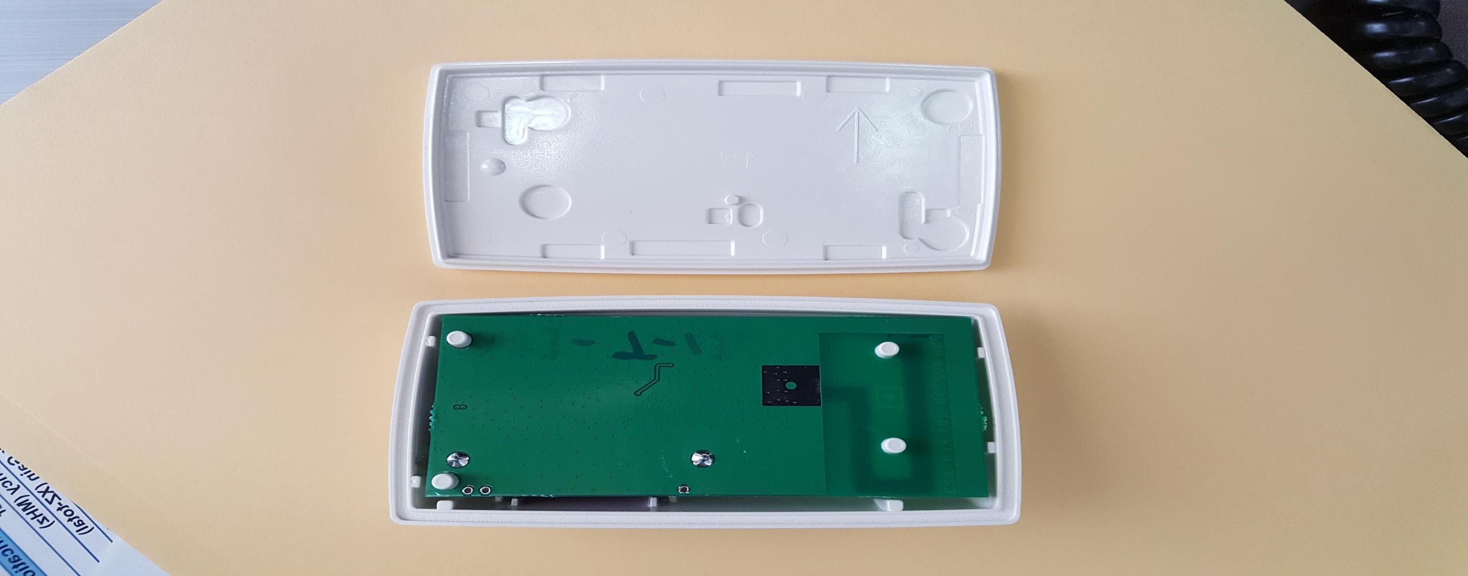
JQU801660C
Jan 27, 2020LMS Interior Transponder
Equipment Class
LMS - Part 90 Location & Monitoring Transmitter
JQU802295AA
Sep 16, 2015Non-multilateral LMS transmitter and receiver
Equipment Class
LMS - Part 90 Location & Monitoring Transmitter
JQU802477
Jun 15, 2014TRP-8100
Equipment Class
LMS - Part 90 Location & Monitoring Transmitter