JQU801531RFM-S Transmitter
KAPSCH TRAFFICCOM CANADA INC.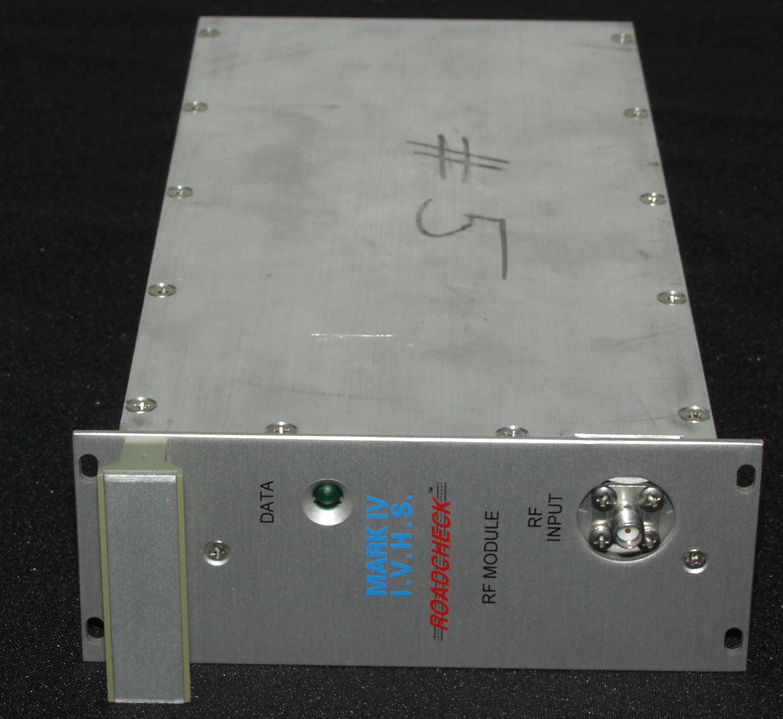
Click to zoom
Application Details
- Equipment Class
- LMS - Part 90 Location & Monitoring Transmitter
- Date of Grant
- Nov 23, 2005
- Application Purpose
- Original Equipment
- Date of Application
- Nov 23, 2005
- Equipment Note
- RFM-S Transmitter
- Frequency Range
- 915.75000000 - 915.75000000
- Country
- Canada
Documents & Files
Document Text
Text extracted from the exhibit documents filed with the FCC. Open a document above to read the original.
Users Manual
Page 1 of 2 © © M M A A R R K K I I V V I I N N D D U U S S T T R R I I E E S S C C o o r r p p . . E E X X C C E E P P T T A A S S M M A A Y Y B B E E O O T T H H E E R R W W I I S S E E P P R R O O V V I I D D E E D D B B Y Y C C O O N N T T R R A A C C T T , , T T H H E E S S E E D D R R A A W W I I N N G G S S A A N N D D S S P P E E C C I I F F I I C C A A T T I I O O N N S S C C O O N N T T A A I I N N P P R R O O P P R R I I E E T T A A R R Y Y I I N N F F O O R R M M A A T T I I O O N N A A N N D D A A R R E E T T H H E E P P R R O O P P E E R R T T Y Y O O F F M M A A R R K K I I V V I I N N D D U U S S T T R R I I E E S S L L T T D D . . A A N N D D A A R R E E I I S S S S U U E E D D I I N N S S T T R R I I C C T T C C O O N N F F I I D D E E N N C C E E A A N N D D S S H H A A L L L L N N O O T T B B E E T T R R A A N N S S M M I I T T T T E E D D O O R R R R E E P P R R O O D D U U C C E E D D O O R R C C O O P P I I E E D D O O R R U U S S E E D D A A S S T T H H E E B B A A S S I I S S F F O O R R M M A A N N U U F F A A C C T T U U R R E E O O R R S S A A L L E E O O F F A A P P P P A A R R A A T T U U S S W W I I T T H H O O U U T T P P R R I I O O R R W W R R I I T T T T E E N N P P E E R R M M I I S S S S I I O O N N . . Mark IV Industries Corp. RFM-S Transmitter Field Testing Guide With Warning Statements Confidential A. Set Up TTS Reader: Serial Comms: RS-232 19200 baud No Parity etc. standard stuff. The cable (null modem) runs out the top of the reader; connect to any DB-9 port on your host computer. Use a Straight through cable (male-female) if you need to extend the length. B. Set up TTS with RFM-S Transmitter: The RFM-S Transmitter must be inserted in Slot #1 (the left most) of the RF Rack. C. List of Commands: (power on default) IAGTEST Help Menu - NOT FOR PRODUCTION USE PT <2-28 hex #> - Program Tag, MASK data must match RT - Read Tag IP - Initialize Tag (FP ff's) FP <2-28 hex #> - Factory Program Tag, MSb must be 1 LP <2-28 hex #> - Lock Program Tag, MSb must be 1 TP <6 hex #> - Trim Program Tag, MSB (FF), IDLE(XX), ACTIVE(XX) (with VERIFY ON, FP is performed with TP data) TL - Lock Trim Values in Tag IC [<#>] - Iteration Count, # of triggers per RT/PT PW [<#>] us - Pulse Width, either 20, 33 or 40 us REPEAT [<#>] - Repeat Count, repeat PT/RT/FP/TP # times - ESC to stop DELAY [<#>|OFF] - Repeat Delay, repeat cycle delay, OFF for no screen updates DETAIL [ON |OFF] - Repeat Detail ON/OFF, show full data during repeat cycles INC [ON |OFF] - Repeat Increment ON/OFF, increment last 4 bytes during PT STAT [ON |OFF] - Repeat Statistics ON/OFF, displays on last cycle VERIFY [ON |OFF] - IP/FP/LP/TP Verify ON/OFF (PT always verifies) PD [<#>] - Program Delay. TXDATA delay between TRIGGER and IP/FP/LP/TP data (NOT header): # us = ~ PD x 2.4 + 60 ex. 250 (default) = ~ 660 us (nominal) CONFIG - Return Configuration Summary The above list can be obtained by typing ?<enter>. Page 2 of 2 © © M M A A R R K K I I V V I I N N D D U U S S T T R R I I E E S S C C o o r r p p . . E E X X C C E E P P T T A A S S M M A A Y Y B B E E O O T T H H E E R R W W I I S S E E P P R R O O V V I I D D E E D D B B Y Y C C O O N N T T R R A A C C T T , , T T H H E E S S E E D D R R A A W W I I N N G G S S A A N N D D S S P P E E C C I I F F I I C C A A T T I I O O N N S S C C O O N N T T A A I I N N P P R R O O P P R R I I E E T T A A R R Y Y I I N N F F O O R R M M A A T T I I O O N N A A N N D D A A R R E E T T H H E E P P R R O O P P E E R R T T Y Y O O F F M M A A R R K K I I V V I I N N D D U U S S T T R R I I E E S S L L T T D D . . A A N N D D A A R R E E I I S S S S U U E E D D I I N N S S T T R R I I C C T T C C O O N N F F I I D D E E N N C C E E A A N N D D S S H H A A L L L L N N O O T T B B E E T T R R A A N N S S M M I I T T T T E E D D O O R R R R E E P P R R O O D D U U C C E E D D O O R R C C O O P P I I E E D D O O R R U U S S E E D D A A S S T T H H E E B B A A S S I I S S F F O O R R M M A A N N U U F F A A C C T T U U R R E E O O R R S S A A L L E E O O F F A A P P P P A A R R A A T T U U S S W W I I T T H H O O U U T T P P R R I I O O R R W W R R I I T T T T E E N N P P E E R R M M I I S S S S I I O O N N . . D. Procedure to test and activate RFM-S: In idle mode the reader generates NO RF. (RFM-S transmitter light off). To turn on the RFM-S transmitter do the following: 1) Set the iteration count to a large number ( IC 1000 ) 2) Issue a read transponder command ( RT ) The iteration count is the number of 20 microsecond trigger pulses the reader will issue for every RT command. for ic=1000 the reader will transmit for about 6-7 seconds. for ic=2000 the time is around 13 seconds. Max is 32767 Ignore all other commands. E. Example: ic 1000 //user input IC=1000 //reader confirms rt //user input READ ERROR //after 1000 trigger pulses (about 6 secs later) reader //responds with "READ ERROR" since (we assume) no transponder //has been read. (The iteration count is persistent. It remains the same unless changed or the reader is reset). F. Warning Statement: This device complies with Part 90 of the FCC Rules. Modifications not expressly approved by the manufacturer may invalidate the user’s authority to operate the equipment
RF Exposure Info
Prediction of MPE limit at a given distance Equation from page 18 of OET Bulletin 65, Edition 97-01where: S = power density P = power input to the antennaG = power gain of the antenna in the direction of interest relative to an isotropic radiatorR = distance to the center of radiation of the antenna Maximum peak output power at antenna input terminal: 21.00 (dBm) * (36dBm-15dB loss) Maximum peak output power at antenna input terminal: 125.8925412 (mW) Antenna gain(typical): 17.1 (dBi) *(15dB +2.1=17.1dBi) Maximum antenna gain: 51.2861384 (numeric) Prediction distance: 35 (cm) Prediction frequency: 915.75 (MHz) MPE limit for uncontrolled exposure at prediction frequency: 0.6105 (mW/cm^2) Power density at prediction frequency: 0.419425 (mW/cm^2) Maximum allowable antenna gain: 18.73031621 (dBi) Margin of Compliance: 1.63031621 Note: 2 4 R PG S π =
RF Exposure Info
MARK IV -IVHS- Confidential TECHNICAL NOTE CC Prepared by: T. Ho Subject: RF Safety Analysis for Service Personnel Working Adjacent to the VRC and IAG Antennas. Reference: IEEE C95.1-1991 requirements for RF safety. There are two parameters required by IEEE C95.1 standards related to RF safety for personnel working adjacent to RF transmission source: 1) power density and 2) specific absorption rate (SAR). 1. Power Density Power density at distance r from a radiated source is given by: P d = P t /(4πr 2 ) where P t is the Equivalent Isotropic Radiation Power (EIRP) of the radiated signal. 2. Specific Absorption Rate (SAR) Rate of absorption of RF radiated energy by a body tissue SAR=σE 2 /(2ρ) where σ: conductivity of body tissue, typical 1100-1200 mS/m E: electric field ρ: tissue density, typical 1.25 g/cm 3 . For MARK IV –IVHS Readers equipped with VRC and/or IAG antenna power density and SAR levels are shown in Figure 1 and 2. Calculation is based on the 4-W EIRP setup level at the antenna with TDMA time frame of 10 ms and RF pulse duty cycle of 25%. RF safety limit in Figure 1 and 2 is extracted from the IEEE C95.1 (1991) requirements for non-controlled environment since it reflects the worst case scenerio. In these figures, data is not applicable in the front and on the side of antenna at distance less that 10 cm due to 10-cm (4”) long of the antenna radom. For the backside of the antenna, this distance is approximately 5 cm. Analysis results show that no risk is anticipated if personnel working in the back of antennas; i.e. on the gantry’s catwalk. Both power density and SAR levels are well below safety limits. 28/09/2005 407/TN2 1 © MARK IV INDUSTRIES LTD. EXCEPT AS MAY BE OTHERWISE PROVIDED BY CONTRACT, THESE DRAWINGS AND SPECIFICATIONS CONTAIN PROPRIETARY INFORMATION AND ARE THE PROPERTY OF MAR K IV INDUSTRIES LTD. AND ARE ISSUED IN STRICT CONFIDENCE AND SHALL NOT BE TRANSMITTED OR REPRODUCED OR COPIED OR USED AS THE BASIS FOR MANUFACTURE OR SALE OF APPARATUS WITHOUT WRITTEN PERMISSION. MARK IV -IVHS- Confidential For personnel working on the side of antennas, the risk level is low if the human body is within 30 cm (1 ft) or greater distance from the antennas. For personnel working in front of the antennas, the risk level is high if the distance between human body to antennas is less than 45 cm (1.5 ft). Specific absorption rate will become more harmful if body exposure exceeds 30 minutes. Recommendations: 1. When VRC antenna or IAG antenna is active, no service should take place which involves personnel working in front or on the side of the antenna at distance less than 2 ft. Otherwise, the antennas transmission must be turned off. 2. No risk is anticipated if personnel working in the back of antennas; i.e. on the gantry’s catwalk. There is no need to turn off RF transmission due to low radiated power in the antenna backlobe. Figure 3. Recommended Limit for Personnel Working Adjacent to Antenna 1 ft Front side of antenna 30 o 1.5 ft Recommended Limit Right side of antenna Left side of antenna Antenna Back side of antenna 2 ft 28/09/2005 407/TN2 2 © MARK IV INDUSTRIES LTD. EXCEPT AS MAY BE OTHERWISE PROVIDED BY CONTRACT, THESE DRAWINGS AND SPECIFICATIONS CONTAIN PROPRIETARY INFORMATION AND ARE THE PROPERTY OF MAR K IV INDUSTRIES LTD. AND ARE ISSUED IN STRICT CONFIDENCE AND SHALL NOT BE TRANSMITTED OR REPRODUCED OR COPIED OR USED AS THE BASIS FOR MANUFACTURE OR SALE OF APPARATUS WITHOUT WRITTEN PERMISSION.
Test Report
Test Report: 5W51196, Issue 2. Applicant: Mark IV Industries 6020 Ambler Drive Mississauga, Ontario L4W 2P1 Apparatus: RFM-S Transmitter FCC ID: JQU 801531 In Accordance With: FCC Part 90, Subpart M 902-928MHz, LMS Systems Tested By: Nemko Canada Inc. 303 River Road Ottawa, Ontario K1V 1H2 Authorized By: Sim Jagpal, General Manager Date: 28 September 2005 Total Number of Pages: 21 Nemko Canada Inc. REPORT SUMMARY Report Number: 5W51196, Issue 2 FCC ID: JQU 801531 Specification: FCC Part 90, Subpart M. Page 2 of 21 Report Summary These tests were conducted on a sample of the equipment for the purpose of demonstrating compliance with FCC Part 90, Sub part M. Conducted measurements were performed in accordance with ANSI TIA-603-B-2002. Radiated tests were conducted is accordance with ANSI C63.4-2003. Radiated emissions are made on an open area test site. A description of the test facility is on file with the FCC. The assessment summary is as follows: Apparatus Assessed: RFM-S Transmitter Specification: FCC Part 90, Subpart M 902-928MHz, LMS Systems Compliance Status: Complies Exclusions: None Non-compliances: None Report Release History: Original Release Author: Xu Jin, Wireless Specialist Note that the results contained in this report relate only to the items tested and were obtained in the period between the date of initial receipt of samples and the date of issue of the report. This test report has been completed in accordance with the requirements of ISO/IEC 17025. Nemko Canada Inc. authorizes the applicant to reproduce this report provided it is reproduced in its entirety and for use by the company’s employees only. Any use which a third party makes of this report, or any reliance on or decisions to be made based on it, are the responsibility of such third parties. Nemko Canada Inc. accepts no responsibility for damages, if any, suffered by any third party as a result of decisions made or actions based on this report. Nemko Canada Inc. REPORT SUMMARY Report Number: 5W51196, Issue 2 FCC ID: JQU 801531 Specification: FCC Part 90, Subpart M. Page 3 of 21 TABLE OF CONTENTS Report Summary......................................................................................................................................... 2 Section 1: Equipment Under Test.............................................................................................................. 4 1.1 Product Identification .................................................................................................................................4 1.2 Samples Submitted for Assessment............................................................................................................4 1.3 Technical Specifications of the EUT ..........................................................................................................5 Section 2: Test Conditions.......................................................................................................................... 6 2.1 Specifications .............................................................................................................................................6 2.2 Deviations From Laboratory Test Procedures ............................................................................................6 2.3 Test Environment .......................................................................................................................................6 2.4 Test Equipment...........................................................................................................................................6 Section 3: Observations .............................................................................................................................. 7 3.1 Modifications Performed During Assessment ............................................................................................7 3.2 Record Of Technical Judgements ...............................................................................................................7 3.3 EUT Parameters Affecting Compliance .....................................................................................................7 3.4 Test Deleted................................................................................................................................................7 Section 4: Results Summary ...................................................................................................................... 8 4.1 FCC Part 90: Test Results ..........................................................................................................................9 Appendix A: Test Results ......................................................................................................................... 10 Section 1. RF Output Power................................................................................................................................10 Section 2. Transmitter Emissions IN Band ............................................................................................................11 Section 3. Spurious Emissions at Antenna Terminals............................................................................................13 Section 4. Radiated Spurious Emissions ................................................................................................................15 Section 6: Frequency Stability ...............................................................................................................................17 Appendix B : Setup Photographs ............................................................................................................ 19 Appendix C : Block Diagram of Test Set-ups......................................................................................... 20 Nemko Canada Inc. SECTION 1: EQUIPMENT UNDER TEST Report Number: 5W51196, Issue 2 FCC ID: JQU 801531 Specification: FCC Part 9…
Text truncated - open the document above for the full version.
Contact Information
Applicant
Alastair Malarky(Chief Engineer)
Technical Contact
Nemko Canada Inc.Russell Grant
[email protected]613-737-9680
303 River Road · Ottawa, Ontario · Canada
Test Firm
Nemko Canada Inc. (Ottawa)Charles Neal
Technical Specifications
| # | Rule Parts | Frequency Range | Power Output | Emission | Tolerance |
|---|---|---|---|---|---|
| 1 | 90.353 | 915.75 MHz - 915.75 MHz | 4 W | 577KK1D | 2.5000000000 ppm |
Other Applications from KAPSCH TRAFFICCOM CANADA INC.
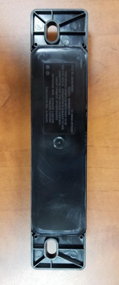
JQU801800C
Sep 13, 2023Non-multilateration LMS Transponder
Equipment Class
LMS - Part 90 Location & Monitoring Transmitter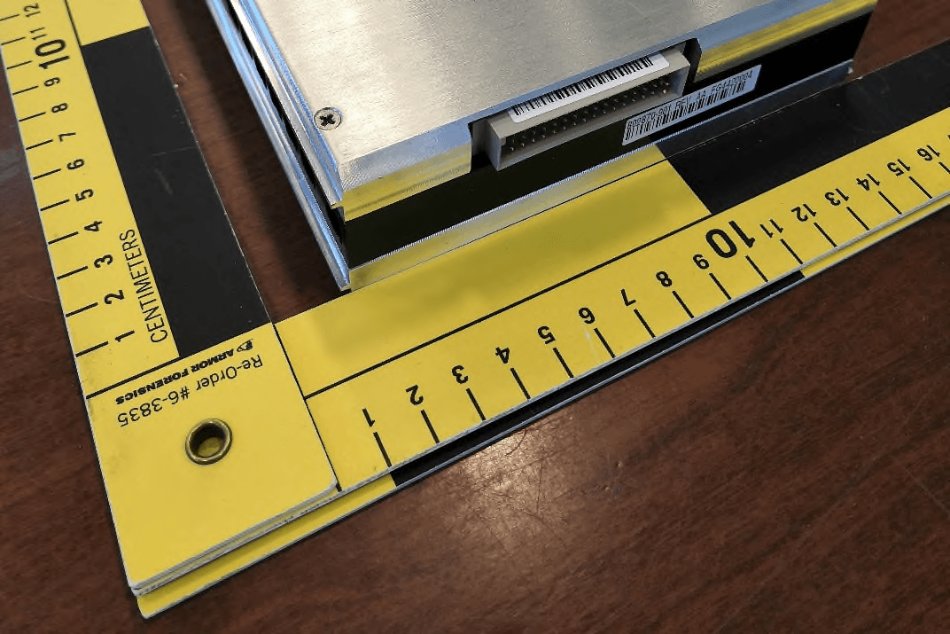
JQU802870
Apr 19, 2021Non-multilateration LMS Tranceiver
Equipment Class
LMS - Part 90 Location & Monitoring Transmitter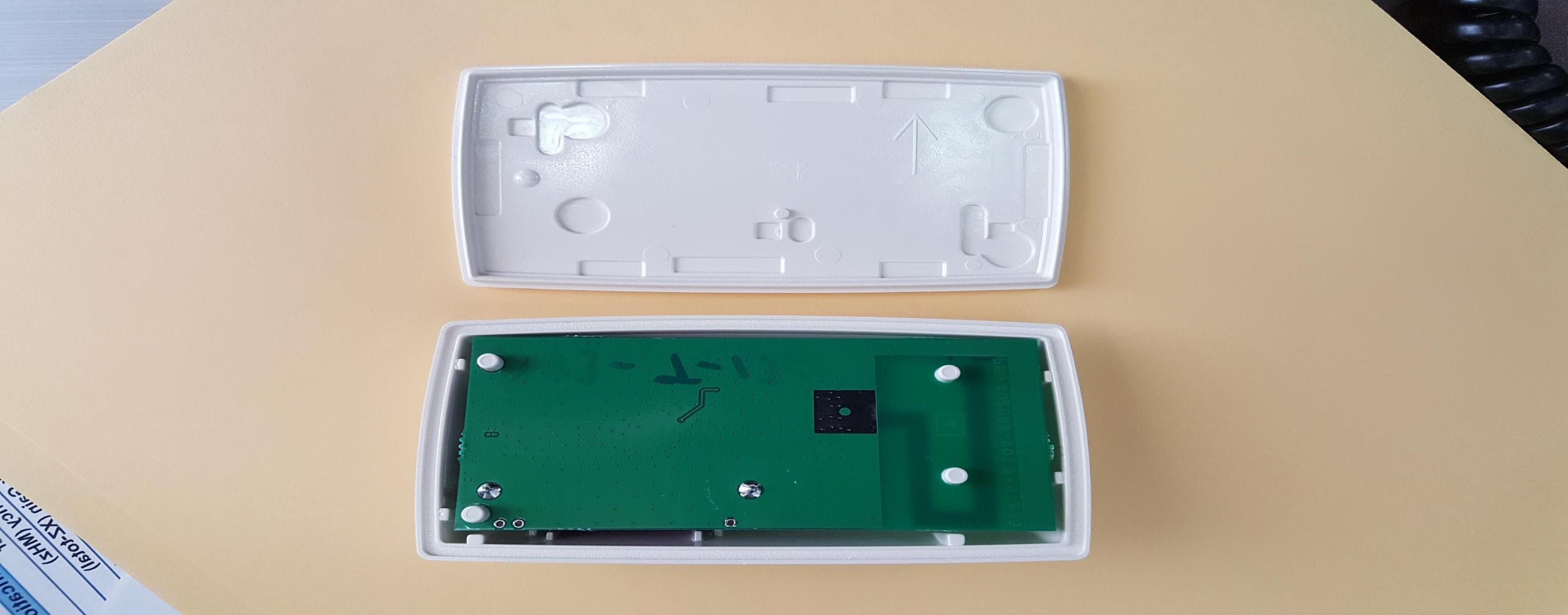
JQU801660C
Jan 27, 2020LMS Interior Transponder
Equipment Class
LMS - Part 90 Location & Monitoring Transmitter
JQU802295AA
Sep 16, 2015Non-multilateral LMS transmitter and receiver
Equipment Class
LMS - Part 90 Location & Monitoring Transmitter
JQU802477
Jun 15, 2014TRP-8100
Equipment Class
LMS - Part 90 Location & Monitoring Transmitter