JQU801800AJanus Exterior Transponder
KAPSCH TRAFFICCOM CANADA INC.Application Details
- Equipment Class
- LMS - Part 90 Location & Monitoring Transmitter
- Date of Grant
- Apr 03, 2011
- Application Purpose
- Original Equipment
- Date of Application
- Mar 31, 2011
- Equipment Note
- Janus Exterior Transponder
- Frequency Range
- 914.40000000 - 915.60000000
- Country
- Canada
Documents & Files
Document Text
Text extracted from the exhibit documents filed with the FCC. Open a document above to read the original.
Users Manual
Kapsch TrafficCom IVHS Front Mount Exterior (FME) Transponder Mounting Instructions for passenger vehicles The FME transponder is recommended for passenger vehicles when the interior transponder cannot be used. The preferred mounting location is on the front license plate using the existing license plate mounting screws while the alternate mounting location is on the front bumper using 3M™ Dual Lock™ fasteners. Preferred FME location: front license plate 1. Remove the two upper license plate mounting screws securing the license plate to the front of the vehicle. 2. Using the license plate mounting screws removed in step 1, secure the transponder, with arrows pointing skyward, and the license plate to the front of the vehicle. Requirements For reliable operation of the transponder, the vehicle must be equipped with only one correctly mounted transponder while passing through a toll facility. Other transponders present in or on the vehicle must be switched off or enclosed in an RF shield. FME transponders must be mounted in the location for which they were programmed. FME transponders programmed for License Plate must be mounted on the front of the vehicle. FME transponders programmed for Rooftop must be mounted on the roof. The mounting location must provide direct line-of-sight communication between the transponder and the toll facility’s overhead antenna. FME transponders cannot be used where local regulations prohibit externally mounting transponders on the roof of the vehicle, the front license plate, front bumper, or other external surfaces. The presence of certain classes of front impact-absorbing materials used in the construction of the vehicle may affect the operation of the FME transponder. The mounting location must be free of such materials. Apply Dual Lock™ fasteners in accordance with 3M™ document 70-0709-4029-4. license plate mounting screw orientation arrow (pointing skyward) FME Mounted on License Plate Optional FME location: front bumper 1. Apply one side of five 3M™ Dual Lock™ fasteners to the FME. a) Using rubbing alcohol, clean the rear surface of the transponder to ensure the bonding surface is free of dirt and any surface contaminants. b) Allow the rear surface of the transponder to dry completely. c) Cut the Dual Lock™ fastener into five 1½ in. lengths. d) Remove the protective backing from one side the five Dual Lock™ fasteners and apply the fasteners equally spaced on the rear of the transponder. ©Kapsch TrafficCom IVHS. All rights reserved Subject to alteration without notice. Dual Lock™ fasteners FME Mounted on Bumper 2. Select the transponder mounting location on the front bumper at the center of the vehicle (as measured from the right and left sides of the vehicle), 15 to 21 in. from the top of the transponder to the road surface. 3. Using rubbing alcohol, clean the mounting location on the bumper. Allow the mounting location to dry completely. 4. Remove the remaining protective backing from the five Dual Lock™ fasteners and press the transponder onto the mounting location on the bumper, ensuring the orientation arrows are pointing skyward. Maintain pressure for 15 seconds to ensure a good bond. 5. Remove the transponder by lifting any corner with sufficient force to separate the Dual Lock™ strips. Do not reuse the Dual Lock™ strips after removing them from the bumper. Obtain new strips as required. Kapsch Group The Kapsch Group and its entities Kapsch TrafficCom, Kapsch CarrierCom and Kapsch BusinessCom are specialized in the future-oriented market segments of Intelligent Transportation Systems (ITS) and Information and Communication Technologies (ICT). Kapsch. Always one step ahead. 801850 - 017 rev A. Kapsch TrafficCom IVHS | 6020 Ambler Drive | Mississauga, Ontario L4W 2P1 | CANADA | Phone +1 905 624 3020 | Fax +1 905 625 6197 54 S. Commerce Way, Suite 100 | Bethlehem, PA 18017 | USA | Phone +1 610 419 1479 | Fax +1 610 419 1489 E-Mail [email protected] | [email protected] | www.kapsch.net centerline of vehicle road surface 15 to 21 in. front bumper FME Rear View
Users Manual
Kapsch TrafficCom IVHS Front Mount Exterior (FME) Transponder Mounting Instructions for trucks and buses The FME transponder is recommended for trucks, buses, coaches, RVs, and other classes of large commercial vehicles. The preferred mounting location is on the roof while the alternate mounting location is on the front of the vehicle. Preferred FME location: roof of vehicle Select a mounting location within 4 in. of the centerline (as measured from the right and left sides of the vehicle). Consider the following criteria: Requirements For reliable operation of the transponder, the vehicle must be equipped with only one correctly mounted transponder while passing through a toll facility. Other transponders present in or on the vehicle must be switched off or enclosed in an RF shield. FME transponders must be mounted in the location for which they were programmed. FME transponders programmed for License Plate must be mounted on the front of the vehicle. FME transponders programmed for Rooftop must be mounted on the roof of the vehicle. The mounting location must provide direct line-of-sight communication between the transponder and the toll facility’s overhead antenna. FME transponders cannot be used where local regulations prohibit externally mounting transponders on the roof of the vehicle, the front license plate, front bumper, or other external surfaces. The presence of certain classes of front impact-absorbing materials used in the construction of the vehicle may affect the operation of the FME transponder. The mounting location must be free of such materials. Apply the 3M™ VHB™ acrylic foam tape that is on the back of the mounting plate in accordance with 3M™ document 70-0704-8701-5. Do not mount behind horns, lights, or other metal objects. Do not mount within 6 in. of any metal object (trailer, decals, horn, lights, or metallic paint-cover surfaces). Do not mount within 2 ft. of any radio transmitter. Do not mount on a slope (+/- 5 deg.) Do not mount more that 13 ft. above roadway. 13 ft. max A non-metal air dam may cover the transponder provided that no metallic paint or metal foil decals cover the dam. If securing the transponder WITH the mounting plate: 1. The back of the mounting plate is covered with 3M™ VHB™ acrylic foam tape. Prepare the mounting location in accordance with 3M™ document 70-0704-8701-5. NOTE: Ensure the mounting plate is installed on the vehicle so that when the transponder is installed on the mounting plate, the orientation arrows on the transponder point in the direction of forward travel. 2. Remove the protective backing from the adhesive on the back of the mounting plate and firmly press the mounting plate against the mounting surface with either a roller or platen pressure, maintaining pressure for 15 seconds to ensure a good bond. 3. Using the supplied tamper-proof nuts, lock washers, and flat washers, secure the transponder to the mounting plate with the notches on the transponder and mounting plate aligned and with the orientation arrows on the transponder pointing in the direction of forward travel. ©Kapsch TrafficCom IVHS. All rights reserved Subject to alteration without notice. Kapsch Group The Kapsch Group and its entities Kapsch TrafficCom, Kapsch CarrierCom and Kapsch BusinessCom are specialized in the future-oriented market segments of Intelligent Transportation Systems (ITS) and Information and Communication Technologies (ICT). Kapsch. Always one step ahead. 801850 - 002 rev C. Kapsch TrafficCom IVHS | 6020 Ambler Drive | Mississauga, Ontario L4W 2P1 | CANADA | Phone +1 905 624 3020 | Fax +1 905 625 6197 54 S. Commerce Way, Suite 100 | Bethlehem, PA 18017 | USA | Phone +1 610 419 1479 | Fax +1 610 419 1489 E-Mail [email protected] | [email protected] | www.kapsch.net If securing the transponder WITHOUT the mounting plate: NOTE: The transponder mounting holes must be used when securing the transponder to the roof of the vehicle using this method. 1. Place the transponder in the selected mounting location. Using the transponder mounting holes as a guide, mark the locations on the roof through which the mounting bolts will pass. Remove the transponder. 2. Drill a mounting bolt hole at both locations marked in step 1. 3. Using two, ¼- in.-diameter stainless steel mounting bolts of sufficient length, two tamper-proof nuts, two lock washers, and two stainless steel flat washers, secure the transponder to the roof of the vehicle with the orientation arrows on the transponder pointing in the direction of forward travel. 4. Apply sealant to the mounting bolts and mounting location as necessary. transponder tamper-proof nut flat washer mounting bolt Alternate FME location: front of vehicle Select a mounting location either on the front license plate using the license plate mounting screws or on the front of the vehicle using the mounting plate. Consider the following criteria: A: a minimum of 24 in. clearance if bumper or large object extends 7+ in. (A 1 ). B: a minimum of 15 in. from the top of the transponder to the roadway for front bumper mounting. C: the transponder must be mounted within 4 in. of the vehicle center. B A B C A A 1 If mounting the transponder on the front license plate: 1. Remove the two upper license plate mounting screws securing the license plate to the front of the vehicle. 2. Using the license plate mounting screws removed in step 1, secure the transponder, with orientation arrows pointing skyward, and the license plate to the front of the vehicle. If mounting the transponder elsewhere on the front of the vehicle: 1. The back of the mounting plate is covered with 3M™ VHB™ acrylic foam tape. Prepare the mounting location in accordance with 3M™ document 70-0704-8701-5. NOTE: Ensure the mounting plate is installed on the vehicle so that when the transponder is installed on the mounting plate, the orientation arrows on the transponder point in the direction of forward travel. 2. Remove the protec…
Text truncated - open the document above for the full version.
ID Label/Location Info
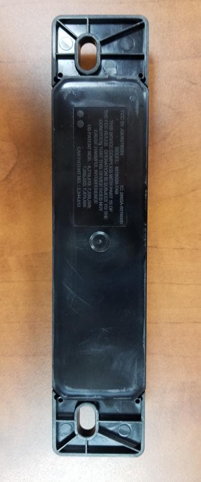
Info Number 801800A Application / 006 Author Alastair Malarky Date 2011 03 07 To Nemko Canada Inc Front Mount Exterior Transponder – Label Location The following defines the label and the location of the label for the Front Mount Exterior Transponder. Label Size 2.25 Width x 1.0 High (inch.) Label Format The figure below shows the label that will be used for the transponder. Label Location The label is located on the rear of each transponder and is engraved into the unit. The location on the unit rear is shown in the following figure. Note the picture does not show the final version of the label text. Label Position
Test Report
www.nemko.com Compliance test report 171119-1TRFWL Date of issue March 28, 2011 FCC Part 90, Subpart M, Section 90.353 LMS operations in the 902–928 MHz band Applicant Kapsch TrafficCom IVHS Corp. Product Front Mount Exterior Transponder Model 801800A-TAB FCC ID JQU801800A Nemko Canada Inc., a testing laboratory, is accredited by the Standards Council of Canada. The tests included in this report are within the scope of this accreditation FCC.doc - Date: March 21, 2010 Report reference ID: 171119-1TRFWL Page 2 of 25 Test location Nemko Canada Inc. 303 River Road Ottawa, ON, K1V 1H2 CANADA Telephone +1 613 737 9680 Facsimile +1 613 737 9691 Toll free +1 800 563 6336 Website www.nemko.com Tested by Andrey Adelberg, Senior Wireless/EMC Specialist Reviewed by David Duchesne, Wireless/EMC Specialist Limits of responsibility Note that the results contained in this report relate only to the items tested and were obtained in the period between the date of initial receipt of samples and the date of issue of the report. This test report has been completed in accordance with the requirements of ISO/IEC 17025. All results contain in this report are within Nemko Canada’s ISO/IEC 17025 accreditation. Copyright notification Nemko Canada Inc. authorizes the applicant to reproduce this report provided it is reproduced in its entirety and for use by the company’s employees only. Any use which a third party makes of this report, or any reliance on or decisions to be made based on it, are the responsibility of such third parties. Nemko Canada Inc. accepts no responsibility for damages, if any, suffered by any third party as a result of decisions made or actions based on this report. © Nemko Canada Inc. Report reference ID: 171119-1TRFWL Page 3 of 25 Table of contents Section 1: Report summary.........................................................................................................................................................4 1.1 Applicant......................................................................................................................................................................4 1.2 Manufacturer................................................................................................................................................................4 1.3 Test specification.........................................................................................................................................................4 1.4 Statement of compliance.............................................................................................................................................4 1.5 Exclusions....................................................................................................................................................................4 1.6 Site registration number...............................................................................................................................................4 1.7 Test report revision history...........................................................................................................................................4 Section 2: Summary of test results.............................................................................................................................................5 2.1 FCC Part 90, Subpart I tests result summary..............................................................................................................5 2.2 FCC Part 90, Subpart M tests result summary............................................................................................................5 Section 3: Equipment under test (EUT) details..........................................................................................................................6 3.1 Product details.............................................................................................................................................................6 3.2 Product description......................................................................................................................................................6 3.3 Sample information......................................................................................................................................................6 3.4 EUT technical specifications........................................................................................................................................6 3.5 Operation of the EUT during testing............................................................................................................................7 3.6 EUT setup diagram......................................................................................................................................................7 Section 4: Engineering considerations.......................................................................................................................................8 4.1 Modifications incorporated in the EUT.........................................................................................................................8 4.2 Deviations from laboratory tests procedures................................................................................................................8 4.3 Technical judgment......................................................................................................................................................8 Section 5: Test conditions...........................................................................................................................................................9 5.1 Atmospheric conditions................................................................................................................................................9 5.2 Power supply range................................................................…
Text truncated - open the document above for the full version.
Contact Information
Applicant
Alastair Malarky(Chief Engineer)
Technical Contact
KAPSCH TRAFFICCOM IVHS CORP.Alastair Malarky
[email protected]905-624-3020
6020 AMBLER DRIVE · Mississauga, Ontario · Canada
Non-Technical Contact
KAPSCH TRAFFICCOM IVHS CORP.Grace Siu
[email protected]905-624-3020
Test Firm
Nemko Canada Inc. (Ottawa)Charles Neal
Technical Specifications
| # | Rule Parts | Frequency Range | Power Output | Emission | Tolerance |
|---|---|---|---|---|---|
| 1 | 90.353 | 914.4 MHz - 915.6 MHz | 1.22 mW | 7M00P1D | 10.0000000000 ppm |
Other Applications from KAPSCH TRAFFICCOM CANADA INC.
JQU801800C
Sep 13, 2023Non-multilateration LMS Transponder
Equipment Class
LMS - Part 90 Location & Monitoring Transmitter
JQU802870
Apr 19, 2021Non-multilateration LMS Tranceiver
Equipment Class
LMS - Part 90 Location & Monitoring Transmitter
JQU801660C
Jan 27, 2020LMS Interior Transponder
Equipment Class
LMS - Part 90 Location & Monitoring Transmitter
JQU802295AA
Sep 16, 2015Non-multilateral LMS transmitter and receiver
Equipment Class
LMS - Part 90 Location & Monitoring Transmitter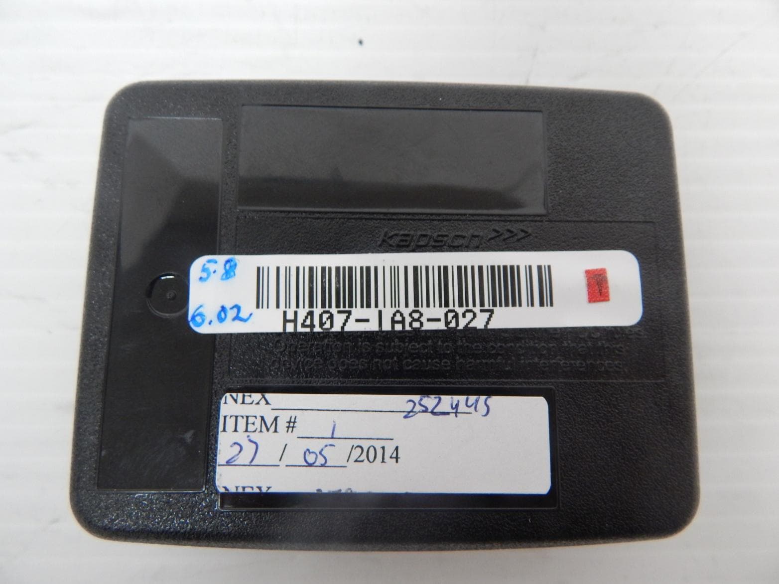
JQU802477
Jun 15, 2014TRP-8100
Equipment Class
LMS - Part 90 Location & Monitoring Transmitter