JQU802120JANUS� HOTPass� Interior OBU
KAPSCH TRAFFICCOM CANADA INC.Application Details
- Equipment Class
- LMS - Part 90 Location & Monitoring Transmitter
- Date of Grant
- Nov 06, 2011
- Application Purpose
- Original Equipment
- Date of Application
- Nov 06, 2011
- Equipment Note
- JANUS� HOTPass� Interior OBU
- Frequency Range
- 914.40000000 - 915.60000000
- Country
- Canada
Documents & Files
Document Text
Text extracted from the exhibit documents filed with the FCC. Open a document above to read the original.
Users Manual
Janus ® HOTPass ® Interior Transponder Mounting Instructions The HOTPass ® interior transponder mounts on the vehicle windshield. The preferred mounting location is between the roofline and the rear view mirror post. If there is not enough room in the preferred mounting location to accommodate the HOTPass ® transponder, the transponder can be mounted beside the rear view mirror post. The HOTPass ® transponder is secured using 3M ™ Dual Lock ™ fasteners. HOTPass® Interior Transponder Mounting Instructions 1. Select a mounting location on the front windshield. The HOTPass ® transponder should be mounted � in., but no more that 2 in. from the roofline. The preferred mounting location is between the roofline and the rear view mirror mounting post, with a minimum of � in. between the transponder and the rear view mirror post. Requirements n For reliable operation of the transponder, the vehicle must be equipped with only one transponder while passing through a toll facility. Other transponders present in or on the vehicle must be switched off or enclosed in an RF shield. n The mounting location must provide direct line-of-sight communication between the transponder and the toll facility overhead antenna. n Do not mount the HOTPass ® transponder on vehicles: u with non-metallic roofs. u with windshields covered in RF-blocking material (ex. metal oxide). u with a metallic center windshield dividing post. u without center-mounted rear view mirrors. n Handheld mobile communication devices must not be located within 12 in. of the transponder. n Metal objects (except for the rear view mirror and the roof ) must not be located within 6 in. of the transponder. n HOTPass ® transponders cannot be used where local regulations prohibit mounting transponders on the windshield. n Apply Dual Lock ™ fasteners in accordance with 3M ™ document. 70-0709-4029-4. Kapsch TrafficCom IVHS roofline � in. preferred, 2 in. maximum � in. minimum rear view mirror post transponder Preferred Mounting Location - Front View orientation arrow rear view mirror post � in. min., 1� in. max orientation arrow � in. preferred, 2 in. maximum roofline Alternate Mounting Location - Front View 3M ™ Dual Lock ™ strips HOTPass ® Transponder - Rear View 2. If there is insufficient space in the preferred location, select an alternate mounting location beside the rear view mirror post: 3. Two 3M ™ Dual Lock ™ on the back of the HOTPass ® transponder are used to mount the transponder to the windshield. Prepare the mounting location in accordance with 3M ™ document 70-0709-4029-4. 4. Remove the protective backing from the two Dual Lock fasteners. 5. Firmly press the HOTPass ® transponder against the windshield in the mounting location, ensuring the orientation arrows are pointing skyward. Maintain pressure for 15 seconds to ensure a good bond. 6. Remove the transponder by lifting any corner with sufficient force to separate the Dual Lock ™ strips. Do not reuse the Dual Lock ™ strips after removing them from the windshield. Obtain new strips as required. ©Kapsch TrafficCom IVHS. All rights reserved. Subject to alteration without notice. 801850-022 Rev A1 Kapsch TrafficCom IVHS | 6020 Ambler Drive | Mississauga, Ontario L4W 2P1 | CANADA | Phone +1 905 624 3020 | Fax +1 905 625 6197 54 S. Commerce Way, Suite 100 | Bethlehem, PA 18017 | Phone +1 610 419 1479 | Fax +1 610 419 1489 E-Mail [email protected] | [email protected] | www.kapsch.net Kapsch Group The Kapsch Group and its entities Kapsch TrafficCom, Kapsch CarrierCom and Kapsch BusinessCom are specialised in the future-oriented market segments of Intelligent Transportation Systems (ITS) and Information and Communication Technology (ICT). Kapsch. Always one step ahead.
External Photos
© 2011 Kapsch TrafficCom IVHS Corp., all rights reserved. These instructions contain confidential and proprietary information and are the property of Kapsch TrafficCom IVHS Corp. and are issued in strict confidence and will be kept confidential and used solely for the purpose intended and for no other purpose and shall not be transmitted, reproduced, copied, and/or used as the basis for manufacture or sale of apparatus unless otherwise agreed to in writing by Kapsch TrafficCom IVHS Corp. Product Name: JANUS® HOTPass® Interior OBU Model Number: 802120-TAB Date: October 5, 2011 Subject: External Pictures HOTPass® Front Photo HOTPass® Black Photo
ID Label/Location Info
© 2011 Kapsch TrafficCom IVHS Corp., all rights reserved. These instructions contain confidential and proprietary information and are the property of Kapsch TrafficCom IVHS Corp. and are issued in strict confidence and will be kept confidential and used solely for the purpose intended and for no other purpose and shall not be transmitted, reproduced, copied, and/or used as the basis for manufacture or sale of apparatus unless otherwise agreed to in writing by Kapsch TrafficCom IVHS Corp. Product Name: JANUS® HOTPass® Interior OBU Model Number: 802120-TAB Date: October 5, 2011 Subject: Label Format and Location
Internal Photos
© 2011 Kapsch TrafficCom IVHS Corp., all rights reserved. These instructions contain confidential and proprietary information and are the property of Kapsch TrafficCom IVHS Corp. and are issued in strict confidence and will be kept confidential and used solely for the purpose intended and for no other purpose and shall not be transmitted, reproduced, copied, and/or used as the basis for manufacture or sale of apparatus unless otherwise agreed to in writing by Kapsch TrafficCom IVHS Corp. Product Name: JANUS® HOTPass® Interior OBU Model Number: 802120-TAB Date: October 5, 2011 Subject: Internal Pictures PCA Front Photo PCA Back Photo
Test Report
FCC 15.407.doc - Date: August 2011 www.nemko.com Compliance test report ID 188681-1TRFWL Date of issue November 4, 2011 FCC 47 CFR Part 90, Subpart M, Section 90.353 LMS operations in the 902–928 MHz band Applicant Kapsch TrafficCom IVHS Corp. Product JANUS ® HOTPass ® Interior OBU Model 802120-TAB FCC ID JQU802120 Nemko Canada Inc., a testing laboratory, is accredited by the Standards Council of Canada. The tests included in this report are within the scope of this accreditation SCC Accredited LAB LAB Accrédité CCN TM w w w . n e m k o . c o m Report reference ID: 188681-1TRFWL Page 2 of 25 Test location Nemko Canada Inc. 303 River Road Ottawa, ON, K1V 1H2 Canada Test site FCC ID: 176392 (3 m semi anechoic chamber) Telephone +1 613 737 9680 Facsimile +1 613 737 9691 Toll free +1 800 563 6336 Website www.nemko.com Tested by Andrey Adelberg, Senior Wireless/EMC Specialist Reviewed by November 4, 2011 Kevin Rose, Wireless/EMC Specialist Date Limits of responsibility Note that the results contained in this report relate only to the items tested and were obtained in the period between the date of initial receipt of samples and the date of issue of the report. This test report has been completed in accordance with the requirements of ISO/IEC 17025. All results contain in this report are within Nemko Canada’s ISO/IEC 17025 accreditation. Copyright notification Nemko Canada Inc. authorizes the applicant to reproduce this report provided it is reproduced in its entirety and for use by the company’s employees only. Any use which a third party makes of this report, or any reliance on or decisions to be made based on it, are the responsibility of such third parties. Nemko Canada Inc. accepts no responsibility for damages, if any, suffered by any third party as a result of decisions made or actions based on this report. © Nemko Canada Inc. w w w . n e m k o . c o m Report reference ID: 188681-1TRFWL Page 3 of 25 w w w . n e m k o . c o m Report reference ID: 188681-1TRFWL Page 4 of 25 Table of Contents Table of Contents ................................................................................................................................................................................................ 4 Section 1 Report summary ......................................................................................................................................................................... 5 1.1 Applicant ................................................................................................................................................................................................. 5 1.2 Manufacturer .......................................................................................................................................................................................... 5 1.3 Test specifications .................................................................................................................................................................................. 5 1.4 Statement of compliance ........................................................................................................................................................................ 5 1.5 Exclusions .............................................................................................................................................................................................. 5 1.6 Test report revision history ..................................................................................................................................................................... 5 Section 2 Summary of test results ............................................................................................................................................................ 6 2.1 FCC Part 90, Subpart I tests result summary ........................................................................................................................................ 6 2.2 FCC Part 90, Subpart M tests result summary ...................................................................................................................................... 6 Section 3 Equipment under test (EUT) details ......................................................................................................................................... 7 3.1 Sample information ................................................................................................................................................................................ 7 3.2 EUT information ..................................................................................................................................................................................... 7 3.3 Technical information ............................................................................................................................................................................. 7 3.4 Product description and theory of operation .......................................................................................................................................... 7 3.5 EUT exercise details .............................................................................................................................................................................. 7 3.6 EUT setup diagram ................................................................................................................................................................................ 8 Section 4 Engineering considerations ...................................................................................................................................................... 9 4.1 Modifications incorporated in the EUT ................................................................................................................................................... 9 4.2…
Text truncated - open the document above for the full version.
Contact Information
Applicant
Alastair Malarky(Chief Engineer)
Technical Contact
KAPSCH TRAFFICCOM IVHS CORP.Alastair Malarky
[email protected]905-624-3020
6020 AMBLER DRIVE · Mississauga, Ontario · Canada
Non-Technical Contact
KAPSCH TRAFFICCOM IVHS CORP.Grace Siu
[email protected]905-624-3020
Test Firm
Nemko Canada Inc. (Ottawa)Charles Neal
Technical Specifications
| # | Rule Parts | Frequency Range | Power Output | Emission | Tolerance |
|---|---|---|---|---|---|
| 1 | 90.353 | 914.4 MHz - 915.6 MHz | 178.00 µW | 6M12P1D | 153.0000000000 ppm |
Other Applications from KAPSCH TRAFFICCOM CANADA INC.
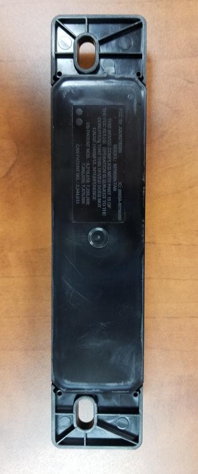
JQU801800C
Sep 13, 2023Non-multilateration LMS Transponder
Equipment Class
LMS - Part 90 Location & Monitoring Transmitter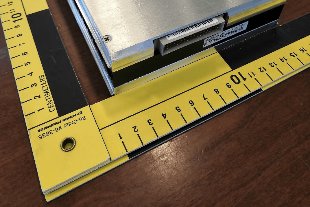
JQU802870
Apr 19, 2021Non-multilateration LMS Tranceiver
Equipment Class
LMS - Part 90 Location & Monitoring Transmitter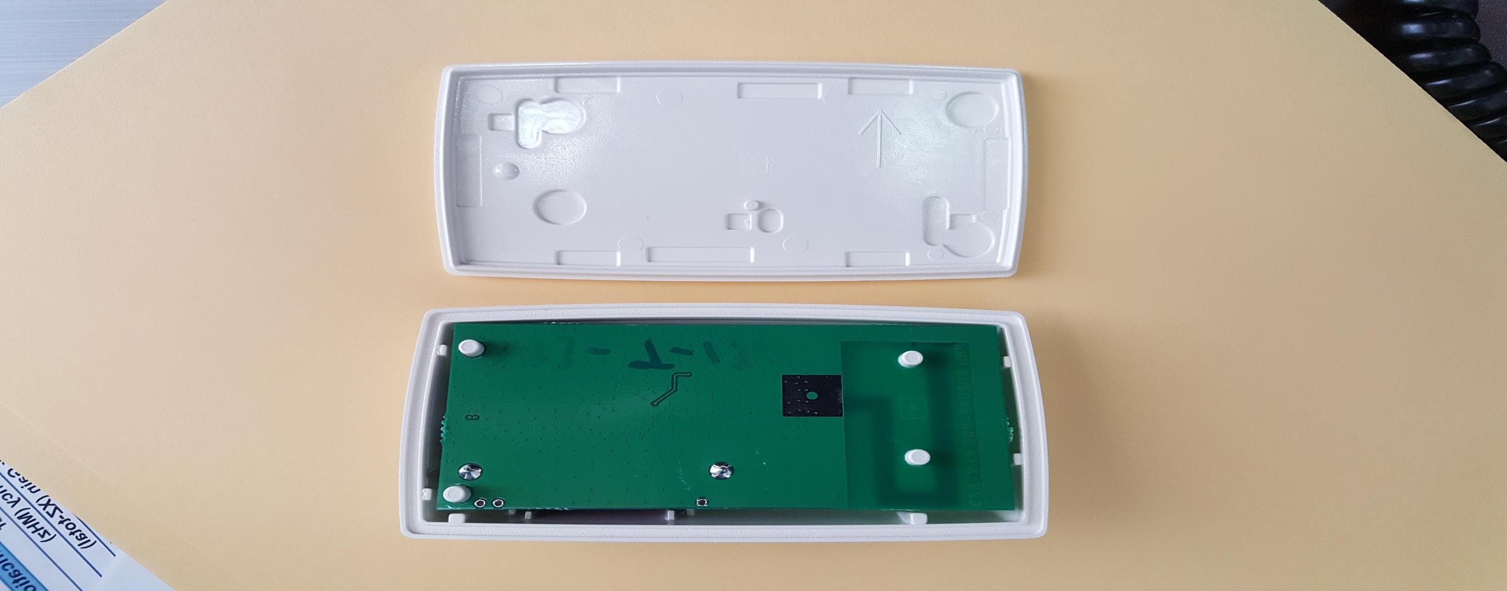
JQU801660C
Jan 27, 2020LMS Interior Transponder
Equipment Class
LMS - Part 90 Location & Monitoring Transmitter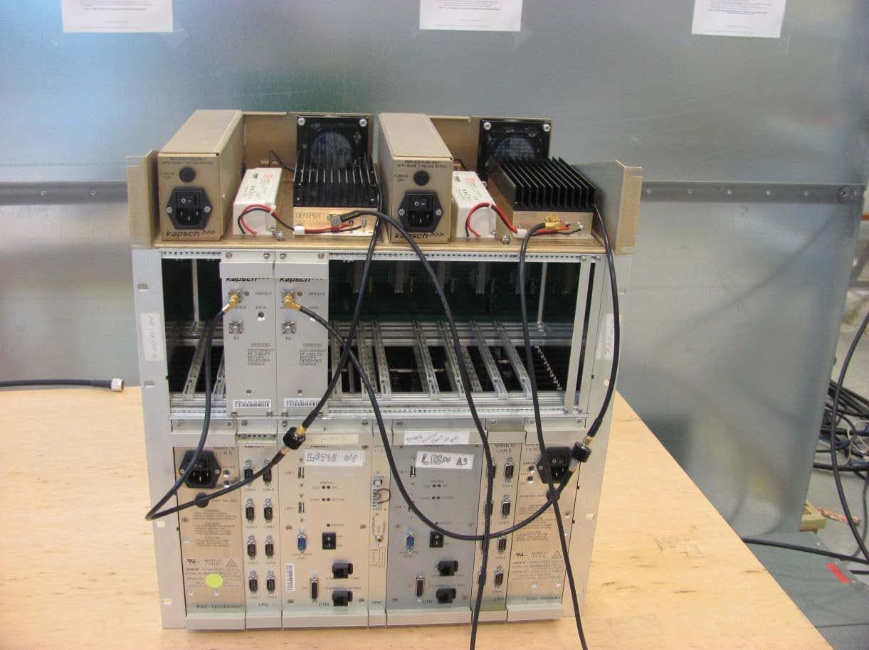
JQU802295AA
Sep 16, 2015Non-multilateral LMS transmitter and receiver
Equipment Class
LMS - Part 90 Location & Monitoring Transmitter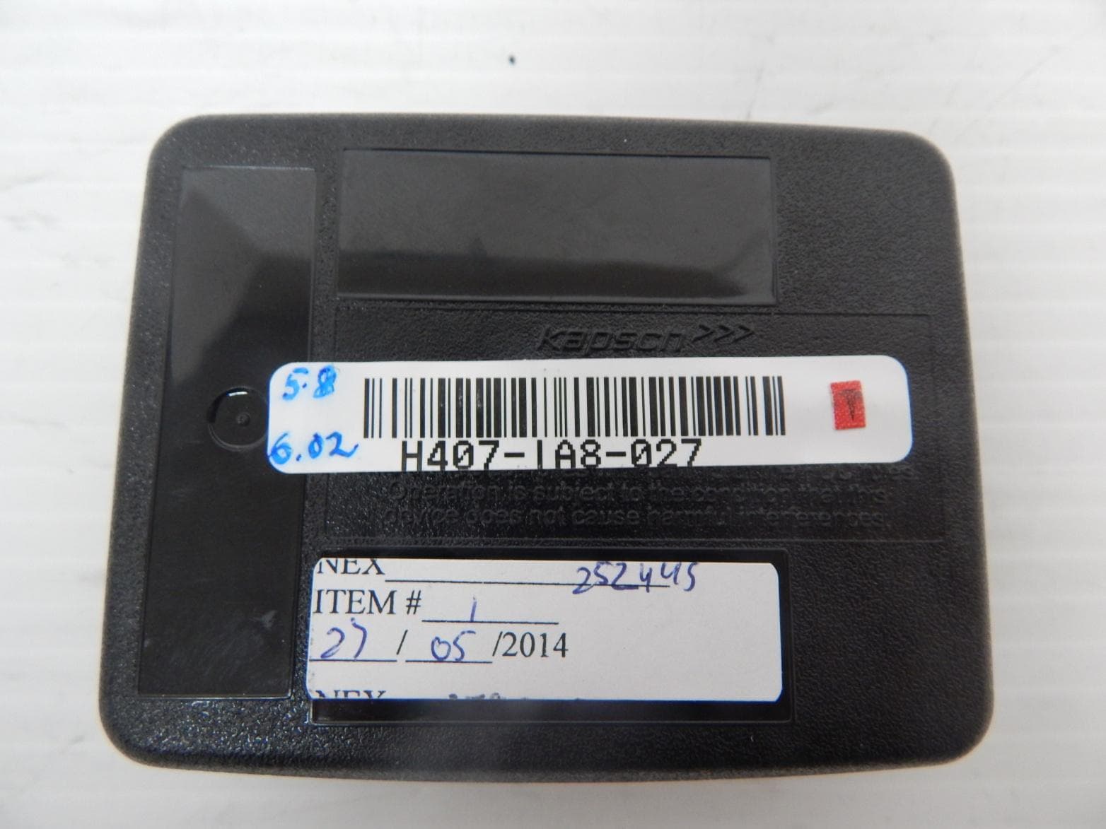
JQU802477
Jun 15, 2014TRP-8100
Equipment Class
LMS - Part 90 Location & Monitoring Transmitter