K9L-4001THATXWireless Remote Controller (TX)
Skytech II, Inc.
Click to zoom
Application Details
- Equipment Class
- DSC - Part 15 Security/Remote Control Transmitter
- Date of Grant
- Apr 22, 2020
- Application Purpose
- Original Equipment
- Date of Application
- Apr 22, 2020
- Equipment Note
- Wireless Remote Controller (TX)
- Frequency Range
- 433.92000000 - 433.92000000
- Company
- Skytech II, Inc.
- Country
- United States
Documents & Files
Document Text
Text extracted from the exhibit documents filed with the FCC. Open a document above to read the original.
Users Manual
Model: 4001TH-A TX REV. 3-31-20 Page 1 Model: 4001TH-A TX INSTALLATION AND OPERATING INSTRUCTIONS IF YOU CANNOT READ OR UNDERSTAND THESE INSTALLATION INSTRUCTIONS DO NOT ATTEMPT TO INSTALL OR OPERATE INTRODUCTION This remote control system was developed to provide a safe, reliable and user-friendly remote control system for gas heating appliances. It has a built-in thermostat. This all battery system operates independently of household current. The system operates on radio frequencies with a non-directional signals. The systems operating range is approximately 20-feet. The system operates on one of 10,000,000 security codes that are programmed into the transmitter at the factory, the remote receiver’s code must be matched to that of the transmitter prior to initial use. It is designed to be used with millivolt gas valves as a dry contact switch. The transmitter has ON and OFF and THERMOSTAT functions. If the LCD screen is not working, check the position of the transmitter’s battery. ON OFF SET LCD Screen ON-OFF Buttons Thermo/Set Button FRONT MODEL: BACK BACK FRONT ON OFF SET 1 2 3 1 ON - Operates unit to ON position, Manually ON. 2 OFF - Operates unit to OFF position, Manually OFF. 3 SET - Sets temperature in THERMO mode. 1 ROOM Temperature 2 ºF or ºC Icon 3 “ON” Flame Icon 4 THERMO Mode 1 2 3 THERMO 4 Liquid Crystal Display (LCD) The transmitter operates on (1) 3V Button Cell (included) that powers the RF signal. Before using the transmitter, the 3V battery must be installed into the battery compartment. Tools Needed: Small jewelers screwdriver To remove the battery holder from the bottom of the transmitter insert a small jewelers screwdriver into the notch at the bottom of the transmitter, then gently pry out the battery holder out. Once it is started, it will pull out with your fingers. Insert the 3-volt button cell battery in the battery holder with the plus (+) side up. See the drawings at the right. It is recommended that CR2032 lithium battery always be used for longer battery life and maximum operational performance. B o t t o m Ed ge Bottom of Transmitter Model: 4001TH-A TX REV. 3-31-20 Page 2 SETTING ºF / ºC •The factory setting for temperature is ºF. To change this setting to ºC, press the ON key and the OFF key on the transmitter at the same time. Follow this same procedure to change from ºC back to ºF. MANUAL FUNCTION To operate the system manually perform the following: ON OPERATION Press the ON key the appliance flame will come ON. The Flame icon will appear on LCD screen in ON mode OFF OPERATION Press the OFF key the appliance flame will shut OFF. The Flame icon will not appear on LCD screen in OFF mode THERMOSTAT FUNCTION SETTING DESIRED ROOM TEMPERATURE This remote control system can be thermostatically controlled when the transmitter is in the THERMO mode (The word THERMO must be displayed on the screen). To set the THERMO MODE and DESIRED room temperature, press the SET button and the word THERMO will appear on the LCD screen; remote is now in the thermostatic mode. TO CHANGE SET TEMPERATURE Press and hold the SET button until the desired set temperature is reached. (By pressing and holding the SET button the LCD screen numbers will increase from 45º to 99º then restart over at 45º again ) Next release the SET button. The LCD screen will display the set temperature for 3 seconds and the LCD screen will flash the set temperature for 3 seconds, then the LCD screen will default to display the room temperature: NOTE: The highest SET temperature is 99º Fahrenheit (37º Celsius) and the lowest temperature is 45º Fahrenheit (7º Celsius). When THERMO is operating in the ON position, the LCD screen will read THERMO at the bottom with the flame icon. See THERMO-ON drawing. When THERMO is OFF, the flame icon will not be displayed. See THERMO-OFF drawing. Press and release the OFF button to disengage the thermo mode. The word THERMO on the LCD screen will not show when the thermo is not in operation. THERMO THERMO-ON THERMO THERMO-OFF THERMO THERMO-SET Model: 4001TH-A TX REV. 3-31-20 Page 3 REMOTE RECEIVER The remote receiver operates on 4 AA-size 1.5V batteries. It is recommended that ALKALINE batteries be used for longer battery life and maximum microprocessor performance. IMPORTANT: New or fully charged batteries are essential for proper operation of the remote receiver. The remote receiver houses the microprocessor that responds to commands from the transmitter to control system operation. The remote receiver has a 3-position slide switch for selecting the MODE of operation: OFF/REMOTE/ON • With the slide switch in the ON position the system will remain on until the slide switch is placed in the OFF or REMOTE position. • With the slide switch in the REMOTE position (centered), the system will only operate if the remote receiver receives commands from the transmitter. If the system does not work see LEARNING TRANSMITTER TO RECEIVER Section. • With the slide switch in the OFF position the system is OFF. • It is suggested that the slide switch be placed in the off position if you will be away from your home for an extended period of time. Placing the slide switch in the OFF position also functions as a safety “lock-out” by both turning the system off and rendering the remote receiver inoperative. Remote Receiver Battery cover slides on/off REMOTE ON OFF Learn Button Requires 4-AA 1.5Volts Ea. (Alkaline batteries) Slide Switch LED Light INSTALLATION INSTRUCTIONS WARNING This remote control system must be installed exactly as outlined in these instructions. Read all instructions completely before attempting installation. Follow instructions carefully during installation. Any modifications of the remote control or any of its components will void the warrant and may be pose a fire hazard. Do not connect any gas valve or electronic module directly to 110-120VAC power. Consult gas appliance manufacturer’s instructions and wiring schematics for proper placement of all wires. All electr…
Text truncated - open the document above for the full version.
Cover Letter(s)
Skytech II, Inc. Date: 2020-03-30 Federal Communications Commission Authorization and Evaluation Division Confidentiality Request regarding application for certification of FCC ID: K9L-4001THATX Pursuant to Sections 0.457 and 0.459 of the Commission’s Rules, we hereby request confidential treatment of information accompanying this application as outlined below: Exhibit Type File Name Schematics Block Diagram Operational Description 4001TH-A TX_Schematics.pdf 4001TH-A TX_Block Diagram.pdf 4001TH-A TX_Operational Description.pdf The above materials contain trade secrets and proprietary information not customarily released to the public. The public disclosure of these materials may be harmful to the applicant and provide unjustified benefits to its competitors. The applicant understands that pursuant to Section 0.457 of the Rules, disclosure of this application and all accompanying documentation will not be made before the date of the Grant for this application. Sincerely, Skytech II, Inc. Signature Michael Rogers / Engineering Manager Typed name an d Title
Cover Letter(s)
Skytech II, Inc. FCC ID: K9L-4001THAT X POWER OF ATTORNEY Date: 2020-03-30 Federal Communications Commission Authorization and Evaluation Division 7435 Oakland Mills Road Columbia, MD 21046 To Whom It May Concern: We, the undersigned, hereby authorize Waltek Services (ShenZhen) Co., Ltd. (Philo Zhong) on our behalf, to apply to the Federal Communications Commission on our equipment. Any and all acts carried out by Waltek Services (ShenZhen) Co., Ltd. (Philo Zhong) on our behalf shall have the same effect as acts of our own. This authorization expires on 2021-03-29. This is to advise that we are in full compliance with the Anti-Drug Abuse Act. We, Skytech II, Inc. are not subject to a denial of federal benefits pursuant to Section 5301 of the Anti-Drug Act of 1988, 21 USC853a, and no party to the application is subject to a denial of federal benefits pursuant to that section. Sincerely, Skytech II, Inc. Signature Michael Rogers / Engineering Manager Typed name and Tile
External Photos
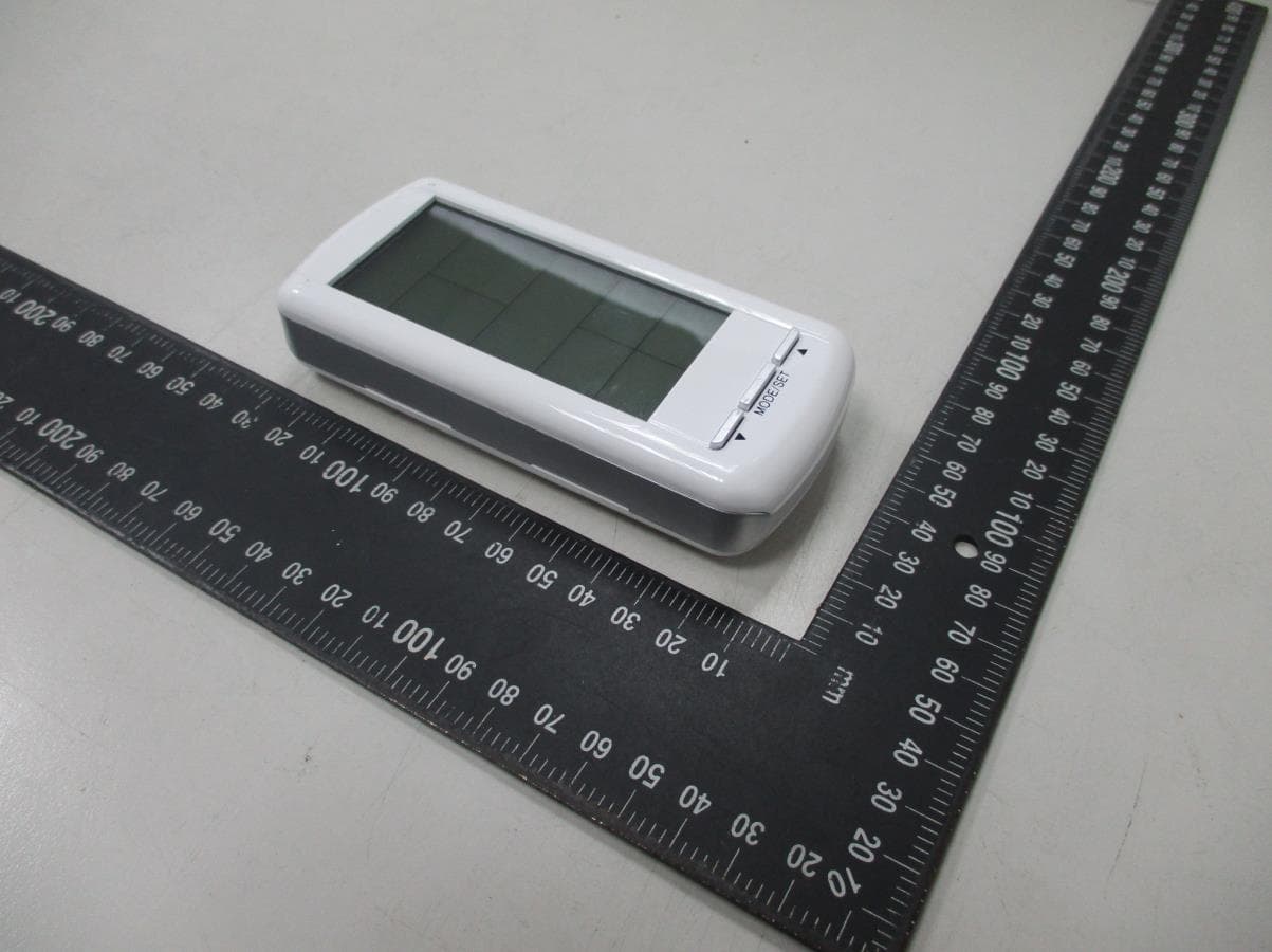
Waltek Services (Shenzhen) Co.,Ltd. http://www.waltek.com.cn 4001TH-A TX - Ext ernal Photos Waltek Services (Shenzhen) Co.,Ltd. http://www.waltek.com.cn Waltek Services (Shenzhen) Co.,Ltd. http://www.waltek.com.cn Waltek Services (Shenzhen) Co.,Ltd. http://www.waltek.com.cn
ID Label/Location Info
4001TH-A TX_Label Sample and Label Location
Internal Photos
Waltek Services (Shenzhen) Co.,Ltd. http://www.waltek.com.cn 4001TH-A TX - Internal Photos Waltek Services (Shenzhen) Co.,Ltd. http://www.waltek.com.cn PCB Printed Antenna Waltek Services (Shenzhen) Co.,Ltd. http://www.waltek.com.cn
Test Report
Waltek Services (Shenzhen) Co.,Ltd. http://www.waltek.com.cn Page 1 of 26 TEST REPORT Reference No. ................... : WTS20S03009623W FCC ID................................. : K9L-4001THATX Applicant............................ : Skytech II, Inc. Address.............................. : 9230 Conservation Way, Ft. Wayne, Indiana 46809, United States Manufacturer...................... : Homewell Technology (Shenzhen) Co.,Ltd Address.............................. : No. 8, 5th Industrial Zone XiaCun, GongMing Town, GuangMing New District, Shenzhen City, Guangdong Province, China Product............................... : Wireless Remote Controller (TX) Model(s)............................. : 4001TH-A TX Standards........................... : FCC CFR47 Part 15 Section 15.231:2019 Date of Receipt sample..... : 2020-03-13 Date of Test........................ : 2020-03-16 to 2020-03-30 Date of Issue...................... : 2020-04-22 Test Result......................... : Pass Remarks: The results shown in this test report refer only to the sample(s) tested, this test report cannot be reproduced, except in full, without prior written permission of the company. The report would be invalid without specific stamp of test institute and the signatures of compiler and approver. Prepared By: Waltek Services (Shenzhen) Co., Ltd. Address: 1/F., Fukangtai Building, West Baima Road, Songgang Street, Baoan District, Shenzhen, Guangdong, China Test Site/Test Location: Waltek Services (Shenzhen) Co., Ltd. Address: 1/F., Fukangtai Building, West Baima Road, Songgang Street, Baoan District, Shenzhen, Guangdong, China Tel :+86-755-83551033 Fax:+86-755-83552400 Compiled by: Approved by: Robin Zhou /Test Engineer Philo Zhong / Manager Reference No.: WTS20S03009623W Page 2 of 26 Waltek Services (Shenzhen) Co.,Ltd. http://www.waltek.com.cn 1 Contents Page COVER PAGE ........................................................................................................................................... 1 1 CONTENTS ............................................................................................................................................... 2 2 REVISION HISTORY ................................................................................................................................. 3 3 GENERAL INFORMATION ....................................................................................................................... 4 3.1 GENERAL DESCRIPTION OF E.U.T.................................................................................................... 4 3.2 DETAILS OF E.U.T. ......................................................................................................................... 4 3.3 TEST MODE .................................................................................................................................... 4 4 EQUIPMENT USED DURING TEST ......................................................................................................... 5 4.1 EQUIPMENTS LIST ........................................................................................................................... 5 4.2 MEASUREMENT UNCERTAINTY ......................................................................................................... 6 4.3 SUBCONTRACTED ........................................................................................................................... 6 5 TEST FACILITY ........................................................................................................................................ 6 6 TEST SUMMARY ...................................................................................................................................... 7 7 RADIATED SPURIOUS EMISSIONS ....................................................................................................... 8 7.1 EUT OPERATION ............................................................................................................................ 8 7.2 TEST SETUP ................................................................................................................................... 9 7.3 SPECTRUM ANALYZER SETUP ........................................................................................................ 10 7.4 TEST PROCEDURE ........................................................................................................................ 11 7.5 SUMMARY OF TEST RESULTS ........................................................................................................ 12 8 PERIODIC OPERATION ......................................................................................................................... 13 9 EMISSION BANDWIDTH ........................................................................................................................ 16 9.1 TEST PROCEDURE ........................................................................................................................ 16 9.2 TEST RESULT ............................................................................................................................... 16 10 ANTENNA REQUIREMENT ................................................................................................................... 17 11 PHOTOGRAPHS – MODEL 4001TH-A TX TEST SETUP PHOTOS .................................................... 18 11.1 PHOTOGRAPH – RADIATED SPURIOUS EMISSIONS TEST SETUP PHOTOS ......................................... 18 12 PHOTOGRAPHS - CONSTRUCTIONAL DETAILS ............................................................................... 20 12.1 MODEL 4001TH-A TX - EXTERNAL PHOTOS .................................................................................. 20 12.2 MODEL 4001TH-A TX - INTERNAL PHOTOS ................................................................................... 24 Reference No.: WTS20S03009623W Page 3 of 26 Waltek Services (Shenzhen) …
Text truncated - open the document above for the full version.
Test Setup Photos
Waltek Services (Shenzhen) Co.,Ltd. http://www.waltek.com.cn 4001TH-A TX Test Setup Photos P hotograph – Radiated Spurious Emissions Test Setup Photos Below 30MHz From 30MHz to 1GHz Waltek Services (Shenzhen) Co.,Ltd. http://www.waltek.com.cn Above 1GHz
Contact Information
Applicant
Michael L. Rogers(Engineering Manager)
Test Firm
WALTEK TESTING GROUP CO., LTD.Joy Zhou
[email protected]0769-22676998
Technical Specifications
| # | Rule Parts | Frequency Range | Power Output |
|---|---|---|---|
| 1 | 15.231 | 433.92 MHz - 433.92 MHz | - |
Other Applications from Skytech II, Inc.
K9LAFTS3TX
Jul 17, 2022Remote control transmitter
Equipment Class
DSC - Part 15 Security/Remote Control TransmitterK9L8001TX
Jun 05, 2021Remote Control Transmitter
Equipment Class
DSC - Part 15 Security/Remote Control TransmitterK9L3001-1TX
Feb 18, 2020Remote Control
Equipment Class
DSC - Part 15 Security/Remote Control Transmitter
K9LREMOTION
Jul 16, 2013Transmiter
Equipment Class
DTS - Digital Transmission System
K9LAFTS1TX
Jul 04, 2012Transmitter
Equipment Class
DSC - Part 15 Security/Remote Control Transmitter