K9LAFTS3TXRemote control transmitter
Skytech II, Inc.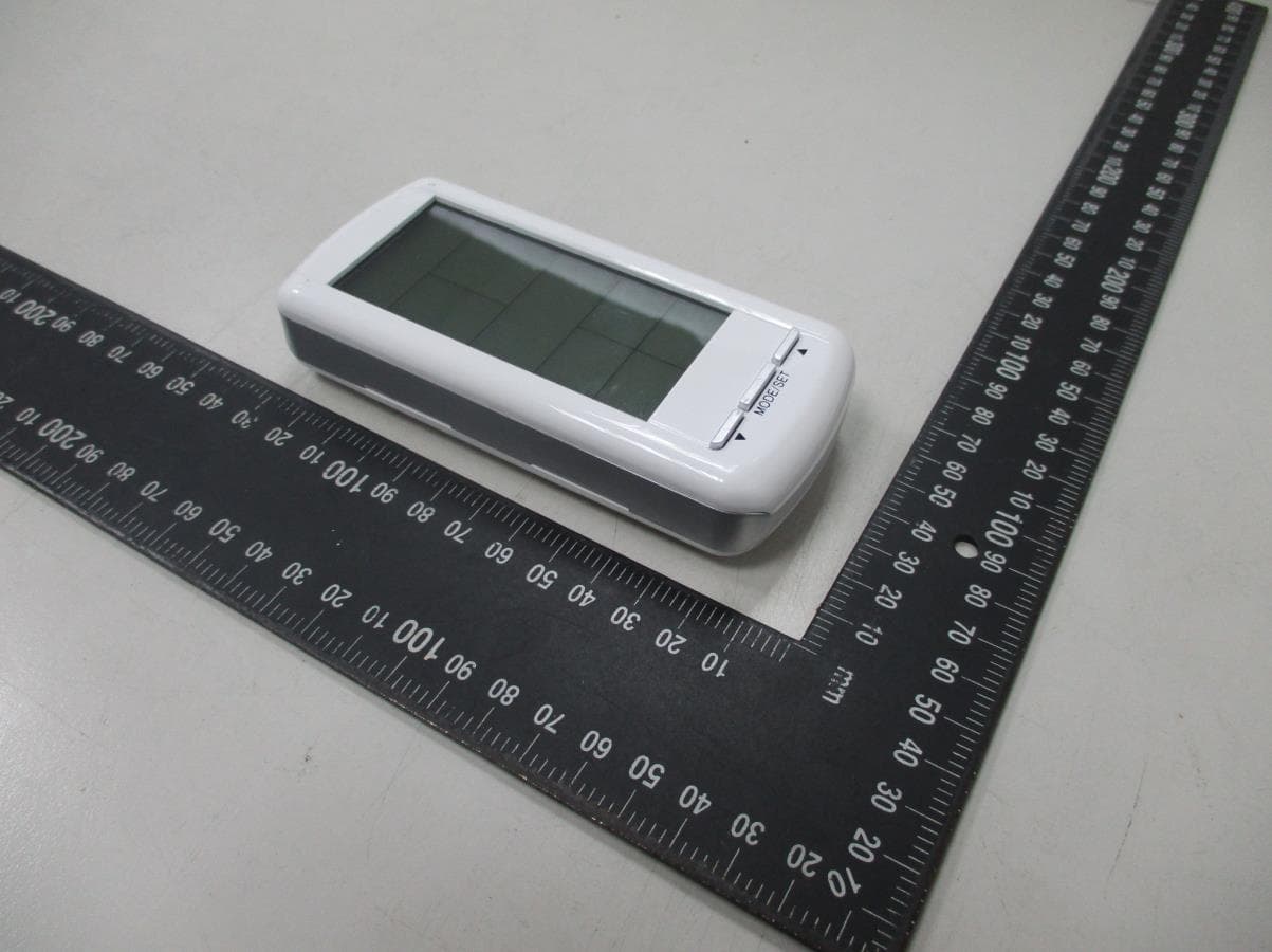
Click to zoom
Application Details
- Equipment Class
- DSC - Part 15 Security/Remote Control Transmitter
- Date of Grant
- Jul 17, 2022
- Application Purpose
- Original Equipment
- Date of Application
- Jul 12, 2022
- Equipment Note
- Remote control transmitter
- Frequency Range
- 303.80000000 - 303.80000000
- Company
- Skytech II, Inc.
- Country
- United States
Documents & Files
Document Text
Text extracted from the exhibit documents filed with the FCC. Open a document above to read the original.
Users Manual
FUNCTIONAL SPECIFICATION VCS-ECOTSS01-1 EcoFlow Touch-Screen Transmitter Revision History Rev. 0: Draft Release. M.R. 12/11/2012. Rev. 1: Clarified transmission delay when cycling to THERMOSTAT mode. M. Rogers 12/12/2012. Rev. 2: Modified transmission delay to include all modes instead of THERMOSTAT mode only. M. Rogers 12/13/2012. Rev. 3: Changed transmission delay from 3-seconds to 2-seconds. M. Rogers 12/12/2012 Rev. 4: Changed transmission frequency from 433.92MHz to 303.0MHz. M.R. 12/17/2012. Rev. 5: Changed reaction to 1 st touch of LCD screen (will only illuminate backlight – no reaction to associated Zone function). M.R. 12/21/2012. Rev. 6: Changed reaction to 1 st press of push-buttons (will only illuminate backlight – no reaction to associated button function). M.R. 2/7/2013. Rev. 7: Changed Room Temperature Limit feature to operate in ALL modes of operation (including OFF modes). M.R. 3/21/2014. Rev. 8: Added LCD display flashing sequence during Main Burner ON and Cont. Pilot ignition sequences. Reference SKCN16-019. M.R. 10/19/2016 Rev. 9: Added “1” Suffix to model number per SKYCN17-006. M. Rogers 5/19/2017. Rev. 10: Clarified Program Setup sequence and factory presets & removed reference to model 5301P, corrected FLAME Zone LCD displays for ON States to include FLAME-B icon and setting. M. Rogers 7/17/2019. Objective Define basic construction, touch-screen LCD & button layout, and operational parameters for a wireless transmitter to operate the Copreci Valve IPI control module. Basic Construction • Transmitter body should be the same construction as model series AF-4000TSS##. • Touch-Screen LCD and three push buttons will allow input from users - the 1 st touch of the LCD screen or press of a push button will only illuminate the backlight (will not respond to associated function). • LCD screen will provide system status & input feedback to user. • Backlight will illuminate LCD screen for 5 seconds after any user input. • Powered via four AAA sized batteries (6V nominal) with LOW BATTERY INDICATOR (5.0V). • Transmission Frequency: 303.8MHz, certified per FCC Part 15B/ANSI C63.4 and IC RSS-210. Touch-Screen LCD and Button Layout (not-to-scale) MODE Zone SET TEMP Zone ROOM TEMP Zone LIGHT Zone FLAME Zone TIME/PROG Zone AUX Zone FAN Zone DOWN Button MODE/SET Button UP Button MODE/SET Functional Description Note: All function adjustments will be automatically accepted 15-seconds after pressing a given touch zone or button. The user may press the MODE/SET button to immediately accept the adjustment manually. Day and Time Display • The current day of week and time of day will be continuously displayed in the TIME/PROG Zone (except during Setup operations). • The day of week will be displayed as one of the following: S, M, T, W, T, F, S • The time of day will be in 12-hour AM, 12-hour PM format. Midnight will be displayed as 12:00am. • Day/Time Setup: o Press and hold the MODE Zone for 5 seconds to enter Day/Time Setup. o Press the UP or DOWN Buttons to adjust the day of week (press the MODE/SET Button or wait for 15 seconds for adjustment to be accepted, then enter hour of day adjustment). o Press the UP or DOWN Buttons to adjust the hour of the day. The time will advance in 1-hour increments; AM and PM will change when the hour advances to 12:00 midnight and 12:00 noon respectively (press the MODE/SET Button or wait for 15 seconds for adjustment to be accepted, then enter minute of hour adjustment). o Press the UP or DOWN Buttons to adjust the minute of the hour. The time will advance in 1-minute increments (press the MODE/SET Button or wait for 15 seconds and the transmitter will exit Day/Time Setup and return to normal operation). o LCD Displays – when in Day/Time Setup: ▪ MODE Zone: Blank ▪ ROOM TEMP Zone: Blank ▪ SET TEMP Zone: Bank ▪ LIGHT Zone: Blank ▪ FAN Zone: Blank ▪ TIME/PROG Zone: Day of Week, or Time of Day will Flash ▪ AUX Zone: Blank ▪ FLAME Zone: Blank Modes of Operation Operation modes: • MANUAL OFF • MANUAL ON • THERMOSTAT • The modes may be cycled in the order above by pressing the MODE Zone or the MODE/SET Button. There will be a 2-second delay before the associated transmission is sent (the display will be updated immediately). MANUAL OFF Mode: • Transmits flame OFF command. • LCD Displays: o MODE Zone: OFF is displayed o ROOM TEMP Zone: Measured temperature is displayed o SET TEMP Zone: Blank o LIGHT Zone: LIGHT and light setting level is displayed o FAN Zone: Blank o TIME/PROG Zone: Current day indicator and current time is displayed o AUX Zone: AUX and AUX setting is displayed o FLAME Zone: Blank MANUAL ON Mode: • Transmits flame ON command • LCD Displays: o MODE Zone: ▪ ON will flash (~0.5 seconds on & ~0.5 seconds off) for 15-seconds, then ON will be displayed continuously. o ROOM TEMP Zone: Measured temperature is displayed o SET TEMP Zone: Blank o LIGHT Zone: LIGHT and light setting level is displayed o FAN Zone: FAN and fan setting level is displayed o TIME/PROG Zone: Current day indicator and current time is displayed o AUX Zone: AUX and AUX setting is displayed o FLAME Zone: Flame-A and Flame-B Icons and flame setting level numbers are displayed THERMOSTAT Mode: • Will cycle flame on and off based on room and set temperatures. Will transmit ON command if SET TEMP (+SWING) is higher than ROOM TEMP and will transmit OFF command if SET TEMP (-SWING) is lower than ROOM TEMP. • Built-in thermostat will measure room temperature. • All programming should be written for deg. F and converted to deg. C when selected. • Temperatures may be displayed in degrees F (factory default) or degrees C. Press the UP and DOWN Buttons simultaneously to change between degrees F and C. • SET TEMP: While in THERMOSTAT mode, press the UP or DOWN Button to change the SET TEMP (45-90 deg. F, 7-32 deg. C); the new set temperature will automatically be accepted after 2 seconds. The factory default SET TEMP is 68 deg. F. • SWING Temperature: This model does not allow for SWING temp…
Text truncated - open the document above for the full version.
Cover Letter(s)
Telefication B.V., Dept. FCC TCB.
External Photos
External photo of EUT
Internal Photos
Internal photo of EUT Internal photo of EUT Internal photo of EUT Internal photo of EUT
Test Setup Photos
Radiated Emission Test set-up photo 9kHz~30MHz Radiated Emission Test set-up photo 30MHz~1GHz Radiated Emission Test set-up photo Above 1GHz
Contact Information
Applicant
Vincent Onaji(Engineering Project Manager)
Technical Contact
Intertek Testing Services Taiwan Ltd.Rico Deng
[email protected]886-3-5191411
No. 11, Lane 275, Ko-Nan 1 Street, Chia-Tung Li, · Taiwan
Non-Technical Contact
Intertek Testing Services Taiwan Ltd.Sunny Liu
[email protected]886-3-5191411
Test Firm
Intertek Testing Services Taiwan Ltd.Lily Shih
Technical Specifications
| # | Rule Parts | Frequency Range | Power Output |
|---|---|---|---|
| 1 | 15.231 | 303.8 MHz - 303.8 MHz | - |
Other Applications from Skytech II, Inc.
K9L8001TX
Jun 05, 2021Remote Control Transmitter
Equipment Class
DSC - Part 15 Security/Remote Control Transmitter
K9L-4001THATX
Apr 22, 2020Wireless Remote Controller (TX)
Equipment Class
DSC - Part 15 Security/Remote Control TransmitterK9L3001-1TX
Feb 18, 2020Remote Control
Equipment Class
DSC - Part 15 Security/Remote Control Transmitter
K9LREMOTION
Jul 16, 2013Transmiter
Equipment Class
DTS - Digital Transmission System
K9LAFTS1TX
Jul 04, 2012Transmitter
Equipment Class
DSC - Part 15 Security/Remote Control Transmitter