K9L3001-1TXRemote Control
Skytech II, Inc.Application Details
- Equipment Class
- DSC - Part 15 Security/Remote Control Transmitter
- Date of Grant
- Feb 18, 2020
- Application Purpose
- Original Equipment
- Date of Application
- Feb 18, 2020
- Equipment Note
- Remote Control
- Frequency Range
- 303.80000000 - 303.80000000
- Company
- Skytech II, Inc.
- Country
- United States
Documents & Files
Document Text
Text extracted from the exhibit documents filed with the FCC. Open a document above to read the original.
Users Manual
1 Hearth & Home Technologies • RCT-MLT-IV Remote Control Instructions • 100-908 Rev. D • 12/19 RCT-MLT-IV Remote Control Kits - Installation and Operating Instructions - INTRODUCTION The remote control system can be operated thermostati- cally or manually from the transmitter. The system operates on radio frequencies (RF) within a 20 foot range. Can be used with DSI, IPI or Standing Pilot systems. This remote control kit has a hand held transmitter that can be used as a remote on/off or as a thermostat. The transmitter display shows the current room temperature, target temperature, timer setting, on/off status, low bat- tery indicator, current time, burner/valve operation and fan operation. Electrical ratings for the receiver are: 110 VAC, 60 Hz, 6 W. If pertinent, see additional fi replace wiring diagrams on pages 9 to 11. INSTALLATION PRECAUTIONS This remote control kit is tested and safe when installed in accordance with this installation manual. WARNING: DO NOT CONNECT 110-120 VAC WIRING TO THE GAS CONTROL VALVE OF THIS APPLIANCE. It is the responsibility of the installer to read all instructions before starting installation and to follow these instructions carefully during installation. Modifi cation of the remote control system or any of its components will void the war- ranty and may cause a fi re hazard. NOTE: The factory installed junction box in the gas fi replace must be wired with 110 VAC before installing this kit. See Installation Instructions section. CAUTION: All wiring should be done by a qualifi ed electri- cian and shall be in compliance with local codes and with the National Electric Code ANSI/NFPA No. 70-current (in the United States), or with the current CSA C22.1 Canadian Electric Code (in Canada). NOTE: A manometer MUST be used to set the manifold pressure on the gas valve. Installation of this kit MUST be done by a qualifi ed service technician. NOTE: This equipment has been tested and found to com- ply with the limits for a Class B digital device, pursuant to Part 15 of the FCC Rules. These limits are designed to pro- vide reasonable protection against harmful interference in a residential installation. This equipment generates, uses, and can radiate radio frequency energy and, if not installed and used in accordance with the instructions, may cause harmful interference to radio communications. However, there is no guarantee that interference will not occur in a particular installation. If this equipment does cause harmful interference to radio or television reception, which can be determined by turning the equipment off and on, the user is encouraged to try to correct the interference by one or more of the following measures: - Reorient or relocate the receiving antenna. - Increase the separation between the equipment and receiver. - Connect the equipment into an outlet on a circuit different from that to which the receiver is connected. - Consult the dealer or an experienced radio TV technician for help. Operating Control E474962 Canadian Equipment Requirements This digital apparatus does not exceed the (Class A/Class B)* limits for radio noise emissions from digital apparatus set out in the Radio Interference Regulations of the Cana- dian Department of Communications. This device complies with Industry Canada license - ex- empt RSS standard(s). Operation is subject to the following two conditions: (1) This device may not cause interference, and (2) This device must accept any interference, includ- ing interference that may cause undesired operation of the device. This device complies with RSS 210 of Industry Canada. This Class B device meets all the requirements of the Ca- nadian interference causing equipment regulations. Le present appareil numerique n’emet pas de bruits ra- dioelectriques depassant les limites applicables aux ap- pareils numeriques (de la class A/de la class B)* pres- crites dans le Reglement sur le brouillage radioelectrique edicte par le ministere des Communications du Canada. Cet appareil est conforme aux normes RSS exemptes de licence d'lndustrie Canada. Le fonctionnement est soumis aux deux conditions suiv- antes: (1) Cet appareil ne doit pas causer d'interférences et (2) Cet appareil doit accepter toute interférence, y compris les interférences pouvant entratner un fonc- tionnement indésirable de l'appareil. Cet appareil est conforme å la norme RSS 210 d'lndustrie Canada. Cet appareil de classe B respecte toutes les exi- gences du réglement canadien sur le matériel brouilleur. FCC REQUIREMENTS WARNING: CHANGES OR MODIFICATIONS TO THIS UNIT NOT EXPRESSLY APPROVED BY THE PARTY RESPONSIBLE FOR COMPLIANCE COULD VOID THE USER’S AUTHORITY TO OPERATE THE EQUIPMENT. 2 Hearth & Home Technologies • RCT-MLT-IV Remote Control Instructions • 100-908 Rev. D • 12/19 Figure 1 INSTALLATION INSTRUCTIONS Installing Electrical Service to the Junction Box RECEIVER WIRING INSTRUCTIONS Incorrect wiring connections WILL cause damage to the gas valve or electronic module operating the gas appliance and may also damage the remote receiver. Wiring Flame Function (Standing Pilot, DSI, IPI) Connect the remote receiver by connecting the two red wires leading from the remote receiver to the red and brown remote wires labeled “FOR USE WITH REMOTE OR WALL SWITCH ONLY”. See Figure 2. Figure 2. Alternative Wiring for units with a wall switch Disconnect the wall switch wire from the TH terminal on the valve and connect this wire to male connector supplied on the receiver. Connect remaining female connector from receiver to the TH terminal on the valve. Adding Optional Fan/Blower Plug 2-prong fan cord directly into the 3 prong polarized plug on the back of the receiver (see Figure 3). This receptacle output is 110/120 VAC, 3 AMP. Wire Colors • Gas Valve - Millivolt or Electronic Ignition .............................................. Red • Fan/Blower - 110 VAC .........................Plug from Fan • Flame Controller - HI/LO solenoid ..................Orange Figure 3. A…
Text truncated - open the document above for the full version.
External Photos
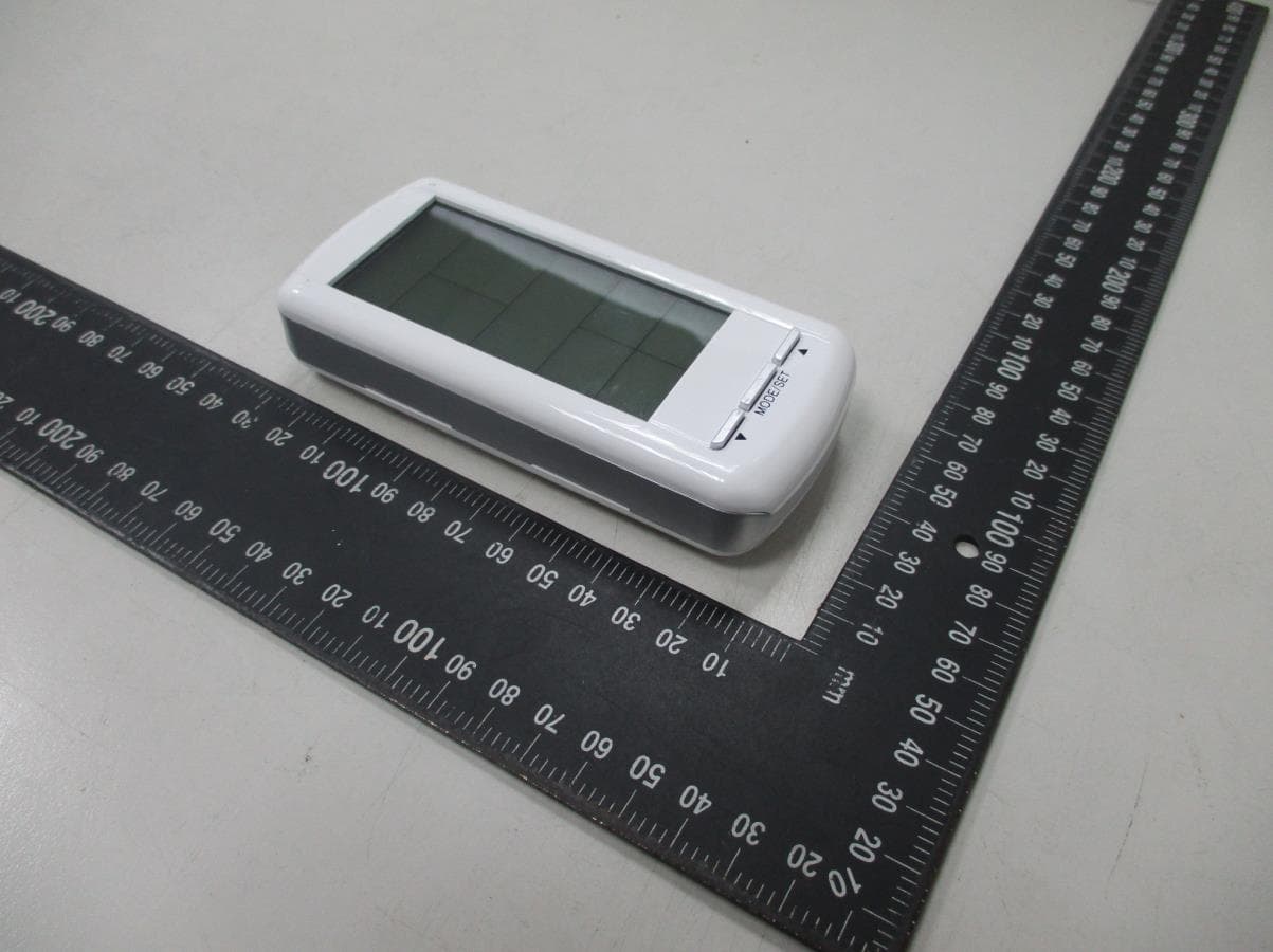
Report Number: MLT1907P15002 Photograph of EUT
ID Label/Location Info
Label Format: Label Position:
Internal Photos
Report Number: MLT1907P15002 Report Number: MLT1907P15002
Test Report
Page: 1 / 29 Report Number: MLT1907P15002 (FCC : Part 15 Subpart C / ANSI C63.10-2013) Product : Remote Control Transmitter Trade Name : Skytech II, Inc., Inc. Model No. : SMART-STAT-IV / SMART-BATT-II / RCT-MLT-IV / RCTS-MLT-IV Applicant : Skytech II, Inc. Applicant Address : 9230 Conservation Way Fort Wayne, Indiana, 46809, USA Page: 2 / 29 Report Number: MLT1907P15002 Report Number MLT1907P15002 Applicant Skytech II, Inc. Product Remote Control Transmitter Sample Received Date 2019/7/22 Sample Tested Date 2019/7/22 ~2020/2/11 Report Prepared By Jesse Tien Signature Date Prepared 2020/2/12 Report Authorized By Roger Chen Signature Date Authorized 2020/2/12 Test By Max Light Technology Co., Ltd. Xi Shiding Dist. New Taipei City 223 Taiwan R.O.C Office : Tel: 886-2-2363-2447 Fax: 886-2-2363-2597 Lab. : Tel: 886-2-2663-3486 Fax: 886-2-2663-3582 It may be duplicated completely for legal use with the allowance of the applicant. It shall not be reproduced except in full, without the written approval of our laboratory. This test report not include the evalution of M.U The test results only relate to the submitted test sample specified above. Page: 3 / 29 Report Number: MLT1907P15002 Table of Contents : History of Test Report .............................................................................................................. 4 1. General ...................................................................................................................... 5 2. Conducted Emissions Requirements ......................................................................... 7 3. Radiated Emissions Requirements ............................................................................ 8 4. Transmitter Bandwidth Measurements .................................................................... 18 5. Transmitter Duty Cycle Measurements ................................................................... 20 6. Verification of De-activation after 5 seconds ........................................................... 24 Appendix I - EUT Test Setup ................................................................................................. 27 Appendix II – Brand / Trade Name & Model No. Multiple Listee ............................................ 29 Page: 4 / 29 Report Number: MLT1907P15002 History of Test Report Original Report Issue Date: 2020/2/12 ■ No additional attachment □ additional attachments were issued as in the following record: Attachment No. Issue Date Description MLT1907P15002 2020/2/12 Original report Page: 5 / 29 Report Number: MLT1907P15002 1. General 1.1 Introduction The following measurement report is submitted on behalf of Skytech II, Inc. In support of an Intentional Periodic Radiator certification in accordance with Part 2 Subpart J and Part 15 Subpart A and C of the Commission’s and Regulations. 1.2 Customer Details Applicant Name Skytech II, Inc. Applicant Address 9230 Conservation Way Fort Wayne, Indiana, 46809, USA Manufacturer Name FEGO PRECISION INDUSTRIAL CO., LTD. Manufacturer Address No. 947 LINSEN RD., WUFONG 41352 TAICHUNG CITY, TAIWAN 1.3 Technical data of EUT Equipment Remote Control Transmitter Model No SMART-STAT-IV / SMART-BATT-II / RCT-MLT-IV / RCTS-MLT-IV FCC ID K9L3001-1TX Power Type Powered by 1.5V x2 Battery (AAA) The EUT is a remote transmitter. The operation frequency is 303.8MHz. 1.4 Description of Support Equipment The EUT itself forms a system. No support equipment is required for its normal operation. Page: 6 / 29 Report Number: MLT1907P15002 1.5 Configuration of System Under Test 1.6 Test Procedure All measurements contained in this report were performed according to the techniques described in Measurement procedure ANSI C63.10: 2013 "Measurement of Intentional Radiators." 1.7 General Test Condition The conditions under which the EUT operates were varied to determine their effect on the equipment's emission characteristics. The final configuration of the test system and the mode of operation used during these tests was chosen as that which produced the highest emission levels. However, only those conditions which the EUT was considered likely to encounter in normal use were investigated. The EUT is a automatic activated device and it will follow the 15.231(e) requirement. 1.8 Test environment : Temperature : 27 Degrees Celsius Relative Humidity : 63 % EUT Page: 7 / 29 Report Number: MLT1907P15002 2. Conducted Emissions Requirements The EUT operates solely by the battery. According to the rule of Section 15.207(c), the EUT exempt to the power line conducted test. Page: 8 / 29 Report Number: MLT1907P15002 3. Radiated Emissions Requirements 3.1 General Configuration: Prior to open-field testing, the EUT was placed in a shielded enclosure and scanned at a close distance to determine its emission characteristics. The physical arrangement of the EUT was varied (within the scope of arrangements likely to be encountered in actual use) to determine the effect on the unit's emanations in amplitude, directivity, and frequency. The exact system configuration which produced the highest emissions was noted so it could be reproduced later during the open-field tests. This was done to ensure that the final measurements would demonstrate the worst-case interference potential of the EUT. 3.2 General Configuration: Final radiation measurements were made on a three-meter, open-field test site. The EUT system was placed on a nonconductive turntable which is 1.5 meters height, top surface 1.0 x 1.5 meter. The spectrum was examined from 300 MHz to 6 GHz in order to cover the whole spectrum below 10th harmonic which could generate from the EUT. During the test, EUT was set to transmit continuously & Measurements spectrum range from 30 MHz to 5 GHz is investigated. For measurements below 1 GHz the resolution bandwidth is set to 100 kHz for peak detection measurements or 120 kHz for quasi-peak detection measurements. Peak detection is used unless otherwise noted as quasi-…
Text truncated - open the document above for the full version.
Test Setup Photos
Report Number: MLT1907P15002 Photograph of Radiated Measurement Front View of The Test Configuration Rear View of The Test Configuration Report Number: MLT1907P15002
Contact Information
Applicant
Michael L. Rogers(Engineering Manager)
Technical Contact
Test Firm
Max Light Technology Co., LTDJesse Tien
Technical Specifications
| # | Rule Parts | Frequency Range | Power Output |
|---|---|---|---|
| 1 | 15.231,15.231(e) | 303.8 MHz - 303.8 MHz | - |
Other Applications from Skytech II, Inc.
K9LAFTS3TX
Jul 17, 2022Remote control transmitter
Equipment Class
DSC - Part 15 Security/Remote Control TransmitterK9L8001TX
Jun 05, 2021Remote Control Transmitter
Equipment Class
DSC - Part 15 Security/Remote Control Transmitter
K9L-4001THATX
Apr 22, 2020Wireless Remote Controller (TX)
Equipment Class
DSC - Part 15 Security/Remote Control Transmitter
K9LREMOTION
Jul 16, 2013Transmiter
Equipment Class
DTS - Digital Transmission System
K9LAFTS1TX
Jul 04, 2012Transmitter
Equipment Class
DSC - Part 15 Security/Remote Control Transmitter