K9LAFTS1TXTransmitter
Skytech II, Inc.
Click to zoom
Application Details
- Equipment Class
- DSC - Part 15 Security/Remote Control Transmitter
- Date of Grant
- Jul 04, 2012
- Application Purpose
- Original Equipment
- Date of Application
- Jul 03, 2012
- Equipment Note
- Transmitter
- Frequency Range
- 303.80000000 - 303.80000000
- Company
- Skytech II, Inc.
- Country
- United States
Documents & Files
Document Text
Text extracted from the exhibit documents filed with the FCC. Open a document above to read the original.
Users Manual
FUNCTIONAL SPECIFICATION SPTS-H/L-TH TRANSMITTER Revision History Rev. 0: Initial Release. M.R. 5/26/2011. Rev. 1: Clarified cycling between settings when in Day/Time and Program Setup modes (wait 5-seconds) and clarified Time setting sequence (advance in 1-minute increments, hour advances every 60 minutes, AM/PM cycle every 12-hours). M. Rogers 6/1/2011. Rev. 2: Updated Touch-Screen LCD and Button layout graphic. Changed MODE Button to MODE/SET Button, added use of MOD/SET Button to accept setting adjustments, increased automatic acceptance time from 5 to 15 seconds. Separated hour and minute time settings with addition of SET button. Added MODE/SET button to Program mode deactivation. Changed temperature unit type selection to two button press (UP and DOWN) to agree with other model transmitters, clarified SWING temperature setting and display. Changed MAIN flame displays to FLAME-A Icon & clarified FLAME Zone display under Program ON operation. Removed references to FLAME Icon in MODE Zone display. Changed SET TEMP to 2-second automatic. M. Rogers 6/13/2011. Rev. 3: Added specific model number. M. Rogers 12/19/2011. Rev. 4: Clarified Low Battery Indicator voltage limit (5.0V), removed Manual OFF from communication safety feature. M. Rogers 12/20/2011. Rev. 5: Added factory default thermostat SET TEMPERATURE, Clarified LCD display in Flame-A adjustment mode, clarified backlight requirement during Child-Lock operation. M. Rogers 12/21/2011. Rev. 6: Clarified Program ON flame zone display (THERMO ON vs THERMO OFF). M. Rogers 12/27/2011. Rev. 7: Added Thermostat Disable Feature & Room Temperature Limit Feature. M. Rogers 3/22/2012. Rev. 8: Clarified Thermostat Disable Feature (TX must be in MANUAL OFF Mode to activate/deactivate feature. M. Rogers 3/27/2012 Objective Define basic construction, touch-screen LCD & button layout, and operational parameters for a wireless transmitter to operate the AF-4000MOD-1 ignition control module. Basic Construction • Transmitter body should be the same construction as current production model SKY- 5301P. • Touch-Screen LCD and three push buttons will allow input from users. • LCD screen will provide system status & input feedback to user. • Blue Backlight will illuminate LCD screen for 5 seconds after any user input. • Powered via four AAA sized batteries (6V nominal) with LOW BATTERY INDICATOR (5.0V). Touch-Screen LCD and Button Layout MODE/SET MODE Zone SET TEMP Zone ROOM TEMP Zone LIGHT Zone (Unused) FAN Zone (Unused) TIME/PROG Zone AUX Zone (Unused) FLAME Zone DOWN Button MODE/SET Button UP Button Functional Description Note: All function adjustments will be automatically accepted 15-seconds after pressing a given touch zone or button. The user may press the MODE/SET button to immediately accept the adjustment manually. Day and Time Display • The current day of week and time of day will be continuously displayed in the TIME/PROG Zone (except during Setup operations). • The day of week will be displayed as one of the following: S, M, T, W, T, F, S • The time of day will be in 12-hour AM, 12-hour PM format. Midnight will be displayed as 12:00am. • Day/Time Setup: o Press and hold the MODE Zone or the MODE/SET Button for 5 seconds to enter Day/Time Setup. o Press the UP or DOWN Buttons to adjust the day of week (press the MODE/SET Button or wait for 15 seconds for adjustment to be accepted, then enter hour of day adjustment). o Press the UP or DOWN Buttons to adjust the hour of the day. The time will advance in 1-hour increments; AM and PM will change when the hour advances to 12:00 midnight and 12:00 noon respectively (press the MODE/SET Button or wait for 15 seconds for adjustment to be accepted, then enter minute of hour adjustment). o Press the UP or DOWN Buttons to adjust the minute of the hour. The time will advance in 1-minute increments (press the MODE/SET Button or wait for 15 seconds and the transmitter will exit Day/Time Setup and return to normal operation). o LCD Displays – when in Day/Time Setup: MODE Zone: Blank ROOM TEMP Zone: Blank SET TEMP Zone: Bank LIGHT Zone: Blank FAN Zone: Blank TIME/PROG Zone: Day of Week, or Time of Day will Flash AUX Zone: Blank FLAME Zone: Blank Modes of Operation Operation modes: • MANUAL OFF • MANUAL ON • THERMOSTAT The modes may be cycled in the order above by pressing the MODE Zone or the MODE/SET Button. MANUAL OFF Mode: • Transmits flame OFF command. • LCD Displays: o MODE Zone: OFF is displayed o ROOM TEMP Zone: Measured temperature is displayed o SET TEMP Zone: Blank o LIGHT Zone: Blank o FAN Zone: Blank o TIME/PROG Zone: Current day indicator and current time is displayed o AUX Zone: Blank o FLAME Zone: Blank MANUAL ON Mode: • Transmits flame ON command • LCD Displays: o MODE Zone: ON is displayed o ROOM TEMP Zone: Measured temperature is displayed o SET TEMP Zone: Blank o LIGHT Zone: Blank o FAN Zone: Blank o TIME/PROG Zone: Current day indicator and current time is displayed o AUX Zone: Blank o FLAME Zone: the FLAME-A Icon is displayed THERMOSTAT Mode: • Will cycle flame on and off based on room and set temperatures. Will transmit ON command if SET TEMP (+SWING) is higher than ROOM TEMP and will transmit OFF command if SET TEMP (-SWING) is lower than ROOM TEMP. • Built-in thermostat will measure room temperature. • All programming should be written for deg. F scale and converted to deg. C when selected. • Temperatures may be displayed in degrees F (factory default) or degrees C. Press the UP and DOWN Buttons simultaneously to change between degrees F and C. • SET TEMP: While in THERMOSTAT mode, press the UP or DOWN Button to change the SET TEMP (45-99 deg. F, 7-37 deg. C); the new set temperature will automatically be accepted after 2 seconds. The factory default SET TEMP is 45 deg. F. • SWING Temperature: o Factory default is 2 degrees F (1 deg. C). o Press and hold the SET TEMP Zone for 5 seconds to enter SWING Adjustment, and press the UP and DOWN Buttons to adjust the SWING temp…
Text truncated - open the document above for the full version.
Attestation Statements
LETTER EXPLAINING PURPOSE OF APPLICATION Radio Cert. No. : FCC: K9LAFTS1TX IC : 2439A-AFTS1TX Data: June. 28, 2012 To whom it may concern: This letter is an application of “Multiple list”. We would like to add nine models in certification of FCC: K9LAFTS1TX & IC: 2439A-AFTS1TX and these models are identical in design and construction, that different is just for sale marketing. The models number list as below. AF-4000TSS01 / AF-4000TSS02 / AF-4000TSS06 / AF-4000TSS07 / AF-4000TSS08 AF-4000TSS09 / RCF-1031TS / RCAF-1031TS-4 / SPTS-H/L-TH Agency Agreement Expiration Date: (Typically 8-12 months) By: __________________________ Christopher Flick (Signature) (Print name) Title: CEO On behalf of: SKYTECH II, INC. (Company Name) Telephone: 260-459-1703
Cover Letter(s)
AGENCY AUTHORIZATION LETTER To whom it may concern: We, the undersigned Skytech II, Inc. , hereby authorize Max Light Technology Co. Ltd. (MLT) of Taiwan to act on our behalf in all matters relating to all processes required in the FCC Part 15 approval and any communication needed with the national authority. Any and all acts carried out by MLT on our behalf shall have the same effects as acts of our own. For questions regarding the authorization, please contact us. Thank you! Sincerely yours, _____________________________________ (Signature) Original written signature of authorized signer: Christopher Flick / CEO Printed name of authorized signer / Title Date: June 14, 2012
Cover Letter(s)
Date: June 14, 2012 Federal Communications Commission Office of Engineering and Technology Equipment Authorization Division 7345 Oakland Mills Road Columbia, Maryland 21046 Subject: Permanent Confidentiality request for FCC ID: K9LAFTS1TX To Whom It May Concern, Pursuant to sections 0.457 and 0.459 of CFR 47, the applicant requests permanent confidential treatment of the following information accompanying this application: Block Diagrams Schematics Operational Descriptions The above materials contain trade secrets and proprietary information not customarily released to the public. The public disclosure of these matters might be harmful to the applicant and provide unjustified benefits to its competitors. Sincerely, Christopher Flick / CEO _____________________________ (Signature)
External Photos
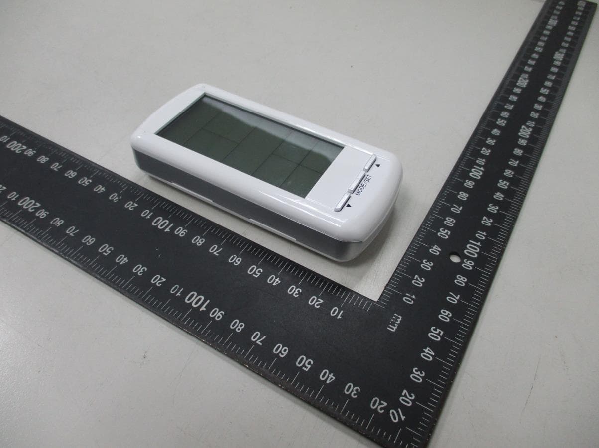
Report Number: MLT1201P15001 Photograph of EUT Report Number: MLT1201P15001
ID Label/Location Info
Report Number: MLT1201P15001 Label Format: Label Position: Equipment Label 21.6mmX43.6mm Rear View
Internal Photos
Report Number: MLT1201P15001 Report Number: MLT1201P15001
Test Report
Page: 1 / 29 Report Number: MLT1201P15001 (FCC : Part 15 Subpart C / ANSI C63.4-2003) Product : Transmiter Trade Name : Skytech II, Inc. Model No. : AF-4000TSS01 (The other see Appendix II) Applicant : Skytech II, Inc. Applicant Address : 9230 Conservation Way Fort Wayne, IN 46809 U.S.A. Page: 2 / 29 Report Number: MLT1201P15001 Report Number MLT1201P15001 Applicant Skytech II, Inc. Product Transmiter Sample Received Date 2012/1/3 Sample Tested Date 2012/1/3 ~2012/5/22 Report Prepared By Jesse Tien Signature Date Prepared 2012/5/31 Report Authorized By Roger Chen Signature Date Authorized 2012/5/31 Test By Max Light Technology Co., Ltd. Room 5, 8F, No.125, Section 3 Roosevelt Road, Taipei, Taiwan., R.O.C. Office : Tel: 886-2-2363-2447 Fax: 886-2-2363-2597 Lab. : Tel: 886-2-2663-3486 Fax: 886-2-2663-3582 It may be duplicated completely for legal use with the allowance of the applicant. It shall not be reproduced except in full, without the written approval of our laboratory. Page: 3 / 29 Report Number: MLT1201P15001 Table of Contents : History of Test Report .............................................................................................................. 4 1. General......................................................................................................................6 2. Conducted Emissions Requirements......................................................................... 8 3. Radiated Emissions Requirements............................................................................ 9 4. Transmitter Bandwidth Measurements.................................................................... 19 5. Transmitter Duty Cycle Measurements................................................................... 21 6. Verification of De-activation after 5 seconds ...........................................................25 Appendix I - EUT Test Setup ................................................................................................. 28 Appendix II – Brand / Trade Name & Model No. Multiple Listee ............................................ 29 Page: 4 / 29 Report Number: MLT1201P15001 History of Test Report Original Report Issue Date: May 31, 2012 ■ No additional attachment □ additional attachments were issued as in the following record: Attachment No. Issue Date Description MLT1201P15001 May 31, 2012 Original report Page: 5 / 29 Report Number: MLT1201P15001 CERTIFICATION We here by verify that : The test data, data evaluation, test procedures and equipment configurations shown in this report were made in accordance with the procedures given in ANSI C63.4-2003. All test were conducted by MLT(Max Light Technology Co., Ltd) Room 5, 8F, No.125, Section 3 Roosevelt Road, Taipei, Taiwan, R.O.C Also, we attest to the accuracy of each. We further submit that the energy emitted by the sample EUT tested as described in the report is in compliance with radiated emission limit of FCC Rules Part 15 Subpart C Section 15.231. Applicant Name Skytech II, Inc. Applicant Address 9230 Conservation Way Fort Wayne, IN 46809 U.S.A. Manufacturer Name FEGO Precision Industrial Co.,Ltd Manufacturer Address 947 Lin-Sen Rd.Wu-Fong Tai-Chung 413 Taiwan ROC Equipment Transmiter Model No AF-4000TSS01 (The other see Appendix II) FCC ID K9LAFTS1TX Report Prepared By Jesse Tien Signature Report Authorized By Roger Chen Signature Page: 6 / 29 Report Number: MLT1201P15001 1. General 1.1 Introduction The following measurement report is submitted on behalf of Skytech II, Inc. In support of an Intentional Periodic Radiator certification in accordance with Part 2 Subpart J and Part 15 Subpart A and C of the Commission’s and Regulations. 1.2 Customer Details Applicant Name Skytech II, Inc. Applicant Address 9230 Conservation Way Fort Wayne, IN 46809 U.S.A. Manufacturer Name FEGO Precision Industrial Co.,Ltd Manufacturer Address 947 Lin-Sen Rd.Wu-Fong Tai-Chung 413 Taiwan ROC 1.3 Technical data of EUT Equipment Transmiter Model No AF-4000TSS01 (The other see Appendix II) FCC ID K9LAFTS1TX Power Type Powered by 6V Battery (AAA Size X4) The EUT is a remote transmitter. The operation frequency is 303.8MHz. Press the button on remote transmitter, can operate the different functions. 1.4 Description of Support Equipment The EUT itself forms a system. No support equipment is required for its normal operation. Page: 7 / 29 Report Number: MLT1201P15001 1.5 Configuration of System Under Test 1.6 Test Procedure All measurements contained in this report were performed according to the techniques described in Measurement procedure ANSI C63.4: 2003 "Measurement of Intentional Radiators." 1.7 General Test Condition The conditions under which the EUT operates were varied to determine their effect on the equipment's emission characteristics. The final configuration of the test system and the mode of operation used during these tests was chosen as that which produced the highest emission levels. However, only those conditions which the EUT was considered likely to encounter in normal use were investigated. The EUT is an automatically activated device and it will follow the 15.231(e) requirement. EUT Page: 8 / 29 Report Number: MLT1201P15001 2. Conducted Emissions Requirements The EUT operates solely by the battery. According to the rule of Section 15.207(c), the EUT exempt to the power line conducted test. Page: 9 / 29 Report Number: MLT1201P15001 3. Radiated Emissions Requirements 3.1 General Configuration: Prior to open-field testing, the EUT was placed in a shielded enclosure and scanned at a close distance to determine its emission characteristics. The physical arrangement of the EUT was varied (within the scope of arrangements likely to be encountered in actual use) to determine the effect on the unit's emanations in amplitude, directivity, and frequency. The exact system configuration which produced the highest emissions was noted so it could be reproduced later during the open-field tests. This was done to ens…
Text truncated - open the document above for the full version.
Test Setup Photos
Report Number: MLT1201P15001 Photograph of Radiated Measurement Front View of The Test Configuration Rear View of The Test Configuration
Contact Information
Applicant
Michael L. Rogers(Engineering Manager)
Technical Contact
Max Light TechnologyJesse Tien
[email protected]886-2-2663-3486
8F-5, No. 125, Sec. 3, Roosevelt Rd. · New Taipei City · Taiwan
Test Firm
Max Light Technology Co., Ltd.Jesse Tien
Technical Specifications
| # | Rule Parts | Frequency Range | Power Output |
|---|---|---|---|
| 1 | 15.231(e) | 303.8 MHz - 303.8 MHz | - |
Other Applications from Skytech II, Inc.
K9LAFTS3TX
Jul 17, 2022Remote control transmitter
Equipment Class
DSC - Part 15 Security/Remote Control TransmitterK9L8001TX
Jun 05, 2021Remote Control Transmitter
Equipment Class
DSC - Part 15 Security/Remote Control Transmitter
K9L-4001THATX
Apr 22, 2020Wireless Remote Controller (TX)
Equipment Class
DSC - Part 15 Security/Remote Control TransmitterK9L3001-1TX
Feb 18, 2020Remote Control
Equipment Class
DSC - Part 15 Security/Remote Control Transmitter
K9LREMOTION
Jul 16, 2013Transmiter
Equipment Class
DTS - Digital Transmission System