K9L-6601TXRemote control transmitter
Skytech II, Inc.
Click to zoom
Application Details
- Equipment Class
- DSC - Part 15 Security/Remote Control Transmitter
- Date of Grant
- Apr 24, 2005
- Application Purpose
- Original Equipment
- Date of Application
- Apr 24, 2005
- Equipment Note
- Remote control transmitter
- Frequency Range
- 433.92000000 - 433.92000000
- Company
- Skytech II, Inc.
- Country
- United States
Documents & Files
Document Text
Text extracted from the exhibit documents filed with the FCC. Open a document above to read the original.
Users Manual
SKY-6601 INSTALLATION AND OPERATING INSTRUCTIONS INTRODUCTION This SKYTECH remote control system was developed to provide a safe, reliable, and user-friendly remote control system for gas heating appliances. The system can be operated thermostatically or manually from the transmitter. The system operates on radio frequencies (RF) within a 20”range using non-directional signals. The system operates one of 256 security codes that are user programmable; the remote receiver’s code must be matched to that of the transmitter prior to initial use. Review COMMUNICATION SAFETY SECTION under TRANSMITTER section and THERMO SAFETY SECTION under REMOTE RECEIVER section. These signal/temperature safety features shut down the fireplace system when a potentially unsafe condition exists. The transmitter operates on 2 AAA-size 1.5V batteries. It is recommended that ALKALINE batteries always be used for longer battery life and maximum operational performance. IMPORTANT: New or fully charged batteries are essential for proper operation of the multi-function transmitter. Insert 2 AAA-size 1.5V batteries into the battery compartment on the back of the transmitter, positioning the (+) and (-) ends of the batteries as indicated on the casing. When the batteries are inserted, the screen at right (with similar numbers) will display. Note: If a LOW battery icon appears on the screen, check the position of the batteries; a reversed battery will not activate transmitter. Note: Due to the sensitive temperature-monitoring components in the transmitter, it may be necessary to allow the transmitter to stabilize to room temperature before accurate room temperatures are displayed on the screen. If the transmitter is TRANSMITTER PM SET LCD DISPLAY F F ROOM activated from a severe cold condition, it can take up to fifteen minutes for accurate temperature readings to appear. 1. LOW-Battery power is low. Replace batteries within two weeks. 2. TIMER-Indicates time remaining before system shuts off, when timer-programmed; 9-hour maximum setting. 3. MODE-Indicates operation MODE of system. ON indicates the system is on, either manually or thermostatically. OFF indicates the entire system is turned off THERMO indicates the system will automatically cycle on/off, depending on programmed 4. SET-Indicates desire SET room temperature for THERMO operation 5. FLAME-Indicates burner/valve in operation. 6. CLOCK-Indicates the current time in AM/PM 7. ROOM-Indicates CURRENT room temperature. 8. indicates degrees Fahrenheit ( indicates degrees Celsius). FUNCTIONS To operate the system, press the MODE button on the front of the transmitter to select the operational MODE desired. l ON indicates the system is on, either manually, timed or thermostatically. l THERMO indicates the system will automatically cycle ON/OFF, depending ON programmed set temperature. l OFF indicates the entire system is turned off. 8 7 SET 6 ROOM PM F FLAME F 5 4 LCD DISPLAY SCREEN 1 TIMER 2 ON OFF THERMO 3 Slide down the plastic cover on the front of the transmitter to expose the “SET” buttons. The Slide cover protects the SET buttons from being changed accidentally. Close the cover after completing the following settings/programming. Flashing numbers on the display indicate the system is awaiting user input, such as using the UP and DOWN buttons to program a new setting. If no change is made to flashing digits within 15 seconds, the system will complete the procedure last programmed and reset the display to its normal state. 1. Press and hold the TIME /TIMER button on the transmitter for more than two seconds. The hour digit(s) will begin flashing. 2. Press the UP or DOWN button until the desired hour is displayed in AM or PM. 3. After setting the desired hour, press and release the TIME/ TIMER button again to set the minutes; the minute digits will begin flashing. 4. Press the UP or DOWN button until the desired minutes are displayed. 5. Press the SET button on the transmitter to stop the time digits from flashing and set the time. The time digits will cease flashing, indicating the clock has been successfully set. SETTING / SCALE The factory setting for temperature is . To change this setting to , first press and hold the UP button and the DOWN button on the transmitter at the same time. Follow this same procedure to change from back to . When changing between the and scales, the temperature in the SET frame defaults to the lowest temperature (45, or 8). The highest SET temperature is 99 Fahrenheit (37 Celsius). F ON OFF THERMO ROOM PM FLAME SET SETTING THE CLOCK TIMER F DOWN TIME/TIMER UP SET MODE BUTTON SETTINGS SETTING DESIRED ROOM TEMPERATURE This remote control system can be thermostatically controlled when the transmitter is in the THERMO mode (THERMO must be displayed on the screen). To set the DESIRED room temperature, press the MODE button to place the transmitter into THERMO mode, then press the UP or DOWN button to select the desired room temperature. The highest SET temperature is 99 Fahrenheit (37 Celsius). OPERATIONAL NOTE: TO CONSERVE BATTERY POWER, CHANGES IN ROOM TEMPERATURE ARE AUTOMATICALLY UPDATED EVERY TWO MINUTES TO THE TRANSMITTER. The Thermo Mode on the transmitter operates the appliance whenever the ROOM TEMPERATURE varies a certain number of degrees from the SET TEMPERATURE. This variation is called the “SWING” or TEMPERATURE DIFFERENTIAL. The normal operating cycle of an appliance may be 2-4 times per hour depending on how well the room or home is insulated from the cold or drafts. A smaller “swing number” increases the number of cycles so the room temperature is more constant. A larger “swing number” decreases the number of cycles, which saves energy, in most cases. The factory setting for the “swing number” is 2. This represents a temperature variation of +/-2 (1) between SET temperature and ROOM temperature, which determines when the fireplace will be activated. The “SWING” number values are: 1=1 (.5), 2=2 (1) and 3=3 (1.6). SETTING T…
Text truncated - open the document above for the full version.
Cover Letter(s)
form (1888x2810x16M jpeg)
External Photos
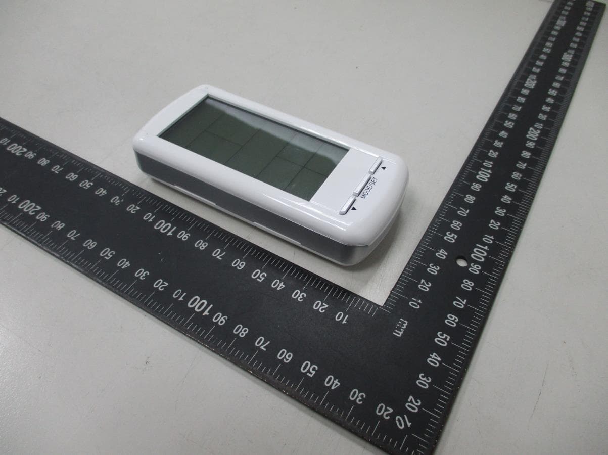
Page 1 CONSTRUCTION PHOTOS OF EUT Page 2
ID Label/Location Info
PDF created with pdfFactory trial version www.pdffactory.com
Internal Photos
Page 3 Page 4 Page 5
Operational Description
FCC ID: K9L-6601TX Report No. RF940222L02 Operational Description The transmitter of the EUT (Remote control transmitter) is powered by 3Vdc battery. The transmitter uses printed antenna and designed to operate on a fixed frequency at 433.92MHz. The other instruction, please have a look at the users manual. This 433.92MHz transmitter device is operated by manual and activate time is less than 5 second after being released.
Test Report
FCC ID: K9L-6601TX Report No.: RF940222L021Report Format Version 2.0.2 FCC TEST REPORT REPORT NO.: RF940222L02 MODEL NO.: SKY-6601 RECEIVED: Feb. 22, 2005 TESTED: Feb. 23, 2005 ISSUED Apr. 14, 2005 APPLICANT: Skytech II, Inc. ADDRESS: 9230 Conservation Way, Fort Wayne, Indiana 46809, U.S.A. ISSUED BY: Advance Data Technology Corporation LAB ADDRESS: No. 47, 14 th Ling, Chia Pau Tsuen, Lin Kou Hsiang 244, Taipei Hsien, Taiwan, R.O.C. TEST LOCATION: No. 19, Hwa Ya 2 nd Rd., Wen Hwa Tsuen, Kwei Shan Hsiang, Taoyuan Hsien 333, Taiwan, R.O.C. This test report consists of 27 pages in total. It may be duplicated completely for legal use with the approval of the applicant. It should not be reproduced except in full, without the written approval of our laboratory. The client should not use it to claim product endorsement by CNLA, A2LA or any government agencies. The test results in the report only apply to the tested sample. 0528 ILAC MRA FCC ID: K9L-6601TX Report No.: RF940222L022Report Format Version 2.0.2 Table of Contents 1.CERTIFICATION ......................................................................................................3 2.SUMMARY OF TEST RESULTS ..............................................................................4 2.1MEASUREMENT UNCERTAINTY ...........................................................................4 3.GENERAL INFORMATION.......................................................................................5 3.1GENERAL DESCRIPTION OF EUT.........................................................................5 3.2DESCRIPTION OF TEST MODES...........................................................................6 3.2.1 CONFIGURATION OF SYSTEM UNDER TEST ...................................................... 6 3.2.2 TEST MODE APPLICABILITY AND TESTED CHANNEL DETAIL: .......................... 7 3.3GENERAL DESCRIPTION OF APPLIED STANDARDS ..........................................8 3.4DESCRIPTION OF SUPPORT UNITS .....................................................................8 4.TEST TYPES AND RESULTS ..................................................................................9 4.1CONDUCTED EMISSION MEASUREMENT ...........................................................9 4.2DEACTIVATION TIME ..............................................................................................9 4.2.1 LIMITS OF DEACTIVATION TIME MEASUREMENT............................................... 9 4.2.2 TEST INSTRUMENTS.............................................................................................. 9 4.2.3 TEST PROCEDURES .............................................................................................. 9 4.2.4 DEVIATION FROM TEST STANDARD .................................................................... 9 4.2.5 TEST SETUP ......................................................................................................... 10 4.2.6 TEST RESULTS ..................................................................................................... 10 4.3RADIATED EMISSION MEASUREMENT ..............................................................12 4.3.1 LIMITS OF RADIATED EMISSION MEASUREMENT............................................ 12 4.3.2 TEST INSTRUMENTS............................................................................................ 14 4.3.3 TEST PROCEDURES ............................................................................................ 15 4.3.4 DEVIATION FROM TEST STANDARD .................................................................. 15 4.3.5 TEST SETUP ......................................................................................................... 16 4.3.6 EUT OPERATING CONDITIONS ........................................................................... 16 4.3.7 TEST RESULTS ..................................................................................................... 17 4.420dB OCCUPIED BANDWIDTH MEASUREMENT................................................23 4.4.1 LIMITS OF BAND EDGES MEASUREMENT ........................................................ 23 4.4.2 TEST INSTRUMENTS............................................................................................ 23 4.4.3 TEST PROCEDURES ............................................................................................ 23 4.4.4 DEVIATION FROM TEST STANDARD .................................................................. 23 4.4.5 TEST SETUP ......................................................................................................... 24 4.4.6 TEST RESULTS ..................................................................................................... 24 5.PHOTOGRAPHS OF THE TEST CONFIGURATION.............................................26 6.INFORMATION ON THE TESTING LABORATORIES ...........................................27 FCC ID: K9L-6601TX Report No.: RF940222L023Report Format Version 2.0.2 1. CERTIFICATION PRODUCT: Remote control transmitter MODEL NO.: SKY-6601 BRAND: SKYTECH APPLICANT: Skytech II, Inc. TESTED: Feb. 23, 2005 TEST SAMPLE: R&D SAMPLE STANDARDS: FCC Part 15, Subpart C (Section 15.231), ANSI C63.4-2003 The above equipment have been tested by Advance Data Technology Corporation, and found compliance with the requirement of the above standards. The test record, data evaluation & Equipment Under Test (EUT) configurations represented herein are true and accurate accounts of the measurements of the sample’s EMC characteristics under the conditions specified in this report. PREPARED BY:, DATE:Apr. 14, 2005 ( Andrea Hsia ) TECHNICAL ACCEPTANCE:, DATE:Apr. 14, 2005 Responsible for RF ( Gary Chang ) APPROVED BY : , DATE: Apr. 14, 2005 ( Cody Chang, Deputy Manager ) FCC ID: K9L-6601TX Report No.: RF940222L024Report Format Version 2.0.2 2. SUMMARY OF TEST RESULTS The EUT has been tested according to the following specifications: APPLIED STANDARD: FCC Part 15, Subpart C STANDARD PARAGR…
Text truncated - open the document above for the full version.
Test Setup Photos
FCC ID: K9L-6601TX Report No.: RF940222L0226Report Format Version 2.0.2 5. PHOTOGRAPHS OF THE TEST CONFIGURATION RADIATED EMISSION TEST
Contact Information
Applicant
Vincent Onaji(Engineering Project Manager)
Technical Contact
Advance Data Technology CorporationCody Chang
[email protected]886-3-3183232
No. 19, Hwa Ya 2nd Rd., Kwei Shan Hsiang · Taoyuan Hsien · Taiwan
Non-Technical Contact
Advance Data Technology CorporationStephanie Hung
[email protected]886-3-3183232
Test Firm
Bureau Veritas CPS (H.K.) Ltd. Taoyuan BranchRichard Chen
Technical Specifications
| # | Rule Parts | Frequency Range | Power Output |
|---|---|---|---|
| 1 | 15.231 | 433.92 MHz - 433.92 MHz | - |
Other Applications from Skytech II, Inc.
K9LAFTS3TX
Jul 17, 2022Remote control transmitter
Equipment Class
DSC - Part 15 Security/Remote Control TransmitterK9L8001TX
Jun 05, 2021Remote Control Transmitter
Equipment Class
DSC - Part 15 Security/Remote Control Transmitter
K9L-4001THATX
Apr 22, 2020Wireless Remote Controller (TX)
Equipment Class
DSC - Part 15 Security/Remote Control TransmitterK9L3001-1TX
Feb 18, 2020Remote Control
Equipment Class
DSC - Part 15 Security/Remote Control Transmitter
K9LREMOTION
Jul 16, 2013Transmiter
Equipment Class
DTS - Digital Transmission System