K9L1300RERemote Control Receiver
Skytech II, Inc.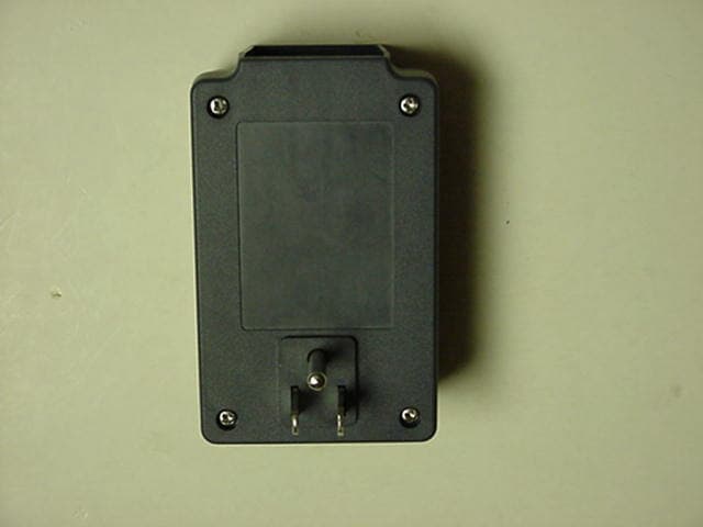
Click to zoom
Application Details
- Equipment Class
- CRR - Superregenerative Receiver
- Date of Grant
- Sep 09, 2002
- Application Purpose
- Original Equipment
- Date of Application
- Sep 09, 2002
- Equipment Note
- Remote Control Receiver
- Frequency Range
- 303.65000000 - 303.65000000
- Company
- Skytech II, Inc.
- Country
- United States
Documents & Files
Document Text
Text extracted from the exhibit documents filed with the FCC. Open a document above to read the original.
Cover Letter(s)
American Telecommunications Certification Body Inc. 6731 Whittier Ave, McLean, VA 22101 August 29, 2002 RE: FCC ID: K9L1300RE Attention: Brian Haghtalab I have a few comments on this Application. 1 The 731 says this is a part 15.121 device. Please note 15.121 is for scanning receivers and this is a superregenerative receiver. The Eq code is CRR. This is FYI, no action is needed on this item. 2 The conducted emissions setup photo does not show the LISN setup. Please provide a photo showing ANSI C63.4 setup for conducted. 3 Label information needs to state what the label is made of and how it is affixed. Please include this information with the label sample. 4 The test was done incorrectly and not in accordance with the currently accepted ANSI C63.4 section 12.1.1.1 (Superregenerative receiver). Please note that this section SPECIFICALLY STATES THAT THE COHERED SIGNAL IS TO BE FROM A SIGNAL GENERATOR, NOT THE MATCHING TRANSMITTER. Please note that you used a matching transmitter for this test. Please retest the unit using the required cohering signal specified in ANSI C63.4. Dennis Ward mailto:[email protected] The items indicated above must be submitted before processing can continue on the above referenced application. Failure to provide the requested information may result in application termination. Correspondence should be considered part of the permanent submission and may be viewed from the Internet after a Grant of Equipment Authorization is issued. Please do not respond to this correspondence using the email reply button. In order for your response to be processed expeditiously, you must submit your documents through the AmericanTCB.com website. Also, please note that partial responses increase processing time and should not be submitted. Any questions about the content of this correspondence should be directed to the sender.
ID Label/Location Info
E E E X X X H H H I I I B B B I I I T T T 2 2 2 C C C l l l a a a s s s s s s “ “ “ B B B ” ” ” L L L a a a b b b e e e l l l i i i n n n g g g F F F o o o r r r m m m a a a t t t LABEL LOCATION – BACK OF UNIT FCC ID:K9L1300RE This device complies with Part 15 of FCC Rules: Operation is subject to the following two conditions: (1) this device may not cause harmful interference, and (2) this device must accept any interference received, including interference that may cause undesired operation. FCCID LABEL
Test Report
R R R F F F M M M e e e a a a s s s u u u r r r e e e m m m e e e n n n t t t R R R e e e p p p o o o r r r t t t P P P r r r e e e p p p a a a r r r e e e d d d b b b y y y : : : N N N a a a t t t i i i o o o n n n a a a l l l C C C e e e r r r t t t i i i f f f i i i c c c a a a t t t i i i o o o n n n L L L a a a b b b o o o r r r a a a t t t o o o r r r y y y 8370 Court Avenue, Suite B-1 Ellicott City, Maryland 21043 (410) 461-5548 F F F o o o r r r : : : SKYTECH II, INC. 9230 Conservation Way Fort Wayne, Indiana 46809 Models: SKY-1310E, 1310PE, 1315E, 1315GE, 1320E, 1321E, 1410E Remote Control Receiver FCC ID: K9L1300RE Demonstration of Compliance with FCC Rules Part 15.109 No part of this report may be reproduced without written approval of National Certification Laboratory September 1, 2002 FCC CERTIFICATION FCCID: K9L1300RE 1 TABLE OF CONTENTS 1.0 Introduction 1.1 Summary 2.0 Description of Equipment Under Test (EUT) 3.0Test Configuration 4.0 Conducted Emissions Scheme 5.0 Radiated Emissions Scheme TABLES Table 1.Support Equipment Table 2.Interface Cables Table 3. Measurement Equipment EXHIBITS Exhibit 1.EUT Photographs NCL PROJ.# SKY – 0593R FCCID: K9L1300RE 2 1.0 Introduction This report has been prepared on behalf of SKYTECH II, INC., to support the attached application for FCC Certification of an Unintentional Radiator. The Equipment Under Test (EUT) was the Models: SKY-1310E, 1310PE, 1315E, 1315GE, 1320E, 1321E, 1410E Remote Control Receiver. Radio-Noise Emissions tests were performed according to the ANSI C63.4- 1992, “Method of Measurement of RFI from Low-Voltage Electronic Equipment in the Range of 9 KHz- 40 GHz”. The measuring equipment conforms to ANSI C63.2 Specifications for electromagnetic Noise and Field Strength-Instrumentation. Test was performed at National Certification Laboratory in Ellicott City, MD. Site description and site attenuation data have been placed on file with the FCC’s sampling and Measurements Branch. FCC acceptance was granted on May 26, 1993. 1.1 Summary The Models: SKY- 1310E, 1310PE, 1315E, 1315GE, 1320E, 1321E, 1410E Remote Control Receiver, complies with the Part 15.109 Radio Limits for an Unintentional Radiator. All models have identical electronic circuit design. Differences are the type of 120 VAC connector implemented, as described in the filing. 2.0 Description of Equipment Under Test (EUT) The EUT Features: FEATURES FREQUENCY Internal PCB Antenna303.65.00 MHz Superregenerative Design Appliance Switch Application 120 VAC Operation FCCID: K9L1300RE 3 3.0 Test Configuration The EUT was setup on the test table in a manner which follows the general guidelines of ANSI C63.4, Section 6 “General Operating Conditions and Configurations.” Tests were performed by exercising the receiver with a CW RF signal level of –20 dBm into a whip antenna from a signal generator. A lamp load was connected to the EUT during testing. The EUT was configured in 3 orthogonal positions to determine the maximum RF level at each emission frequency. The data tables give the EUT position designation that produces worst-case field strength, in an X, Y, Z system. This is described below: 4.0 Conducted Emissions Scheme The EUT is placed on an 80 cm high 1 X 1.5 meter non-conductive table. Power to the CPU is provided through a Solar Corporation 50 Ω/50 μH line Impedance Stabilization Network bonded to a 2.2 X 2 meter horizontal ground plane, and a 2.2 X 2 meter vertical ground plane. The LISN has its AC input supplied from filtered AC power source. A separate LISN provides AC power to the peripheral equipment. I/O cables are moved about to obtain maximum emissions. The 50Ω output of the LISN is connected to the input of the spectrum analyzer and emissions in the frequency range of 450 kHz to 30 MHz are searched. The detector function is set to quasi- peak and the resolution bandwidth is set at 9 kHz, with all post-detector filtering no less than 10 times the resolution bandwidth for final measurements. All emissions within 20 dB of the limit are recorded in the data tables. 5.0 Radiated Emissions Scheme The EUT was initially scanned in the frequency range 30 to 3040 MHz indoors, at a distance of one (1) meter to determine its emissions profile. The EUT was then placed on an 80 cm high 1 X 1.5 meter non-conductive motorized turntable for radiated testing on the 3-Meter open area test site. The emissions from the EUT are measured continuously at every azimuth by rotating the FCCID: K9L1300RE 4 turntable. Waveguide horn and log periodic broadband antennas are mounted on an antenna mast to determine the height of maximum emissions. The height of the antenna is varied between one (1) and four (4) meters. Both the horizontal and vertical field components are measured. The output from the antenna is connected to the input of the spectrum analyzer. The detector function is set to Peak. All emissions within 20 dB of the limit are recorded in the data table. Measurements from 30-1000 MHz:The output from the antenna is connected to the input of the spectrum analyzer. The detector function is set to Quasi-Peak. The resolution bandwidth of the spectrum analyzer system is set at 120 kHz for the range 30-1000 MHz with all post- detector filtering no less than 10 times the resolution bandwidth. Measurements from 1-4 GHz:The output from the horn antenna is connected to the input of a 30 dB pre-Amp, which is in turn attached to the spectrum analyzer. The detector function is set to Peak. The resolution bandwidth of the spectrum analyzer system is set at 1 MHz for the range 1-4 GHz. To convert the spectrum analyzer reading into a quantified E-field level to allow comparison with the FCC limits. It is necessary to account for various calibration factors. These factors include cable loss (CL) and antenna factors (AF). The AF/CL in dB/m is algebraically added to the Spectrum Analyzer voltage in dBμV/m. This level is then compared with the FCC limit. EXAMPLE: Spectrum Analyzer Volt:VdBμV Compo…
Text truncated - open the document above for the full version.
Contact Information
Applicant
Michael L. Rogers(Engineering Manager)
Technical Contact
National Certification LaboratoryBrian Haghtalab
[email protected](410) 461-5548
8370 Court Avenue · Ellicott City, Maryland · United States
Non-Technical Contact
National Certification LaboratoryBrian Haghtalab
[email protected](410) 461-5548
Test Firm
National Certification LaboratoryBrian Haghtalab
Technical Specifications
| # | Rule Parts | Frequency Range | Power Output |
|---|---|---|---|
| 1 | 15B | 303.65 MHz - 303.65 MHz | - |
Other Applications from Skytech II, Inc.
K9LAFTS3TX
Jul 17, 2022Remote control transmitter
Equipment Class
DSC - Part 15 Security/Remote Control TransmitterK9L8001TX
Jun 05, 2021Remote Control Transmitter
Equipment Class
DSC - Part 15 Security/Remote Control Transmitter
K9L-4001THATX
Apr 22, 2020Wireless Remote Controller (TX)
Equipment Class
DSC - Part 15 Security/Remote Control TransmitterK9L3001-1TX
Feb 18, 2020Remote Control
Equipment Class
DSC - Part 15 Security/Remote Control Transmitter
K9LREMOTION
Jul 16, 2013Transmiter
Equipment Class
DTS - Digital Transmission System