K9L3002REMOTE CONTROL TRANSMITTER
Skytech II, Inc.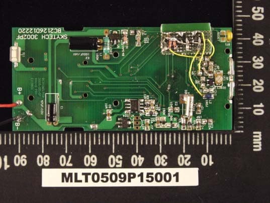
Click to zoom
Application Details
- Equipment Class
- DSC - Part 15 Security/Remote Control Transmitter
- Date of Grant
- Oct 24, 2005
- Application Purpose
- Original Equipment
- Date of Application
- Oct 24, 2005
- Equipment Note
- REMOTE CONTROL TRANSMITTER
- Frequency Range
- 303.80000000 - 303.80000000
- Company
- Skytech II, Inc.
- Country
- United States
Documents & Files
Document Text
Text extracted from the exhibit documents filed with the FCC. Open a document above to read the original.
Users Manual
3002P Instruction LCD DISPLAY 1. PROGRAM FOR: Flashes when programming days of week and periods of the day. When in normal state, only current DAY displays. When programming or in PROGRAM mode, both day and week will display. 2. DAY – Flashes when current day or day of week is being programmed. 3. PERIOD – Flashes when current period of day or period of week is being programmed. 4. MODE – Indicates operation MODE of system. ON indicates the system is on, either manually or thermostatically. OFF indicates the entire system is turned off. THERMO indicates the system will automatically cycle ON/OFF, depending on programmed SET temperature. PROGRAM – Indicates the system is operating with PROGRAMMED settings. 5. START AT – Flashes when programming the time to turn system ON. 6. SET – Indicates desired SET room temperature, when in THERMO or PROGRAM mode. 7. 0F/ 0C – Factory programmed in 0F.( 0C indicates degrees in Celsius.) 8. TIME/TEMP – Displays the CURRENT room temperature. In same frame the current time will display in AM or PM. You must depress the TIME/TIMER button to display current time. 9. LOW – Battery power is low. Replace batteries within 2 weeks. 10. TIMER – When displayed indicates countdown timer in operation. 11. OVERRIDE – Displays when “programmed”” SET temperature is overridden. 12. FLAME – Single or double flame symbol indicates burner/valve is operational. 13. HOLD – Displays when “programmed” SET temperature is overridden and will hold that temperature until cancelled or next program period change. 14. CP – Displays when CHILD PROOF “LOCK-OUT” is engaged. Pressing the UP and TIMER buttons together, engages CP. 15. SWING- Displays in SET frame when setting TEMPERATURE DIFFERENTIAL. 16. FAN – Indicates the fan is on (when fan blade displayed). OFF indicates fan is not in operation. FUNCTIONS To operate the system, press the MODE button on the transmitter to select the operational MODE desired. 1. ON indicates the system is on, either manually or thermostatically. 2. OFF indicates the entire system is turned off. 3. THERMO indicates the system will automatically cycle ON/OFF, depending on programmed set temperature. 4. PROGRAM indicates the system will automatically cycle ON and OFF in the programmed mode depending on the 7 day/4 period program that is in memory. BUTTON SETTINGS Flip down the plastic cover on the front of the transmitter to expose the “SET” buttons. The flip cover protects the SET buttons from being changed accidentally. Close the cover after completing the following settings/programming. Flashing numbers on the display indicate the system is awaiting user input, such as using the UP and DOWN buttons to program a new setting. If no change is made to flashing digits within 15 seconds, the system will complete the procedure last programmed and reset the display to its normal state. INITIAL SET-UP PROGRAMMING OF TRANSMITTER Follow the procedures below, upon FIRST USE of transmitter, setting the following program options: 1. TEMPERATURE SETTING – 0F (Fahrenheit) or 0C (Celsius) 2. CURRENT DAY OF WEEK – SU, MO, TU, WE, TH, FR, SA 3. CURRENT TIME OF DAY – Hours and minutes 4. FLAME CONTROLLER – HI/LO solenoid CHANGING THE TEMPERATURE SCALE 1. After pressing the small button in the battery compartment to start the set up process the 0F symbol will begin flashing on the LCD screen. 2. To change 0F to 0C, press the UP or DOWN button on the front of the transmitter. 3. After setting/confirming the preferred temperature SCALE, press the SET button on the front of the transmitter. NOTE: You will need to press the SET button, confirming 0F if you want the temperature readings to be in 0F. SETTING THE CURRENT DAY OF THE WEEK 1. Following Step 3 on the previous page, the symbol SU will begin flashing on the LCD screen. 2. To change to the CURRENT day of the week, press the AHEAD or BACK button on the front of the transmitter. 3. After setting/confirming the current Day of the week, press the SET button on the front of the transmitter. SETTING THE CURRENT HOUR AND MINUTES 1. Following Step 3 above, the HOUR digits will begin flashing in the TIME frame on the LCD screen. 2. To set the current HOUR, press the UP or DOWN button setting the HOUR for the corresponding AM/PM time period. 3. After setting the current HOUR, press the SET button on the front of the transmitter, and the MINUTE digits will begin flashing on the LCD screen 4. To set the current MINUTES, press the UP or DOWN button setting the correct MINUTES. 5. After setting the HOURS and MINUTES, press the SET button on the front of the transmitter SETTING THE FLAME CONTROLLER 1. Following step 5 above, two flames, words HI FLAME will begin flashing on the LCD screen. 2. On this 3324R system press SET this will set the flame controller to HI/LO operation. 3. You can push the UP or DOWN button setting HI/LO or MODULATION on the LCD screen. 4. NOTE: The 3324R solenoid will only work when the flame controller is set to HI/LO. PROGRAMMING THE TRANSMITTER 1. Press the PROG button for 4 seconds. The shaded boxes on the LCD screen with the words PROGRAM FOR and START AT will begin to flash. The current DAY, PERIOD, TIME and SET temperature of the BUILT-IN FACTORY PROGRAM will also be displayed. 2. To program the DAY and PERIOD OF DAY, press the AHEAD or BACK buttons to display the DAY and PERIOD you wish to program. 3. When the DAY and PERIOD being programmed displays, then press the PROG button and the TIME will flash on the LCD screen. 4. To program the START TIME, press the UP or DOWN button. Programmed start time settings are in 15 minute segments. The new set time will display on the LCD screen. 5. When the desired START TIME displays, press the PROG button and the SET TEMPERATURE will flash on the LCD screen. 6. To program the SET TEMPERATURE, press the UP or DOWN button. 7. When the desired SET TEMPERATURE displays, then press the PROG button. 8. After pressing the PROG button in step 7, the next PERIOD of the sa…
Text truncated - open the document above for the full version.
Block Diagram
LCD Driver MCU Set timer & clock Key input Temperature RF output LCD Display
Cover Letter(s)
DATE: 10/27/2005 Declaration of Software Modification Timco Engineering, Inc. 849 NW State Road 45 P. O . B o x 3 7 0 Newberry, Florida 32669 ID: K9L3002 To Whom It May Concern: Skytech II Inc., in accordance with Part 15.231(e), hereby declare that Skytech II Inc. will modify the software to make sure the device will not transmit any signal within 10 seconds even if the operator activates or presses the button. In Addition, Skytech II Inc. declares that the soft modification will be finished before marketing. Applicant: Skytech II, Inc. By: Wei-Cheng, Hsueh Title: Electronic Engineer
External Photos
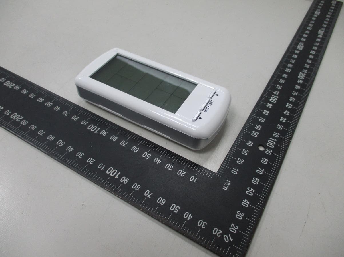
MAX LIGHT Technology Lab MAX LIGHT Technology Lab MAX LIGHT Technology Lab MAX LIGHT Technology Lab MAX LIGHT Technology Lab
ID Label/Location Info
Technology Lab Label Format: Label Position: Equipment Label 2.0cmX1.0cm Rear View This device complies with Part 15 of the FCC Rules. Operation is subject to the following two conditions: (1) This device may not cause harmful interference, and (2) This device must accept any interference received, including. Interference that may cause undesired operation. Model No: 3002P FCC ID: K9L3002
Internal Photos
MAX LIGHT Technology Lab MAX LIGHT Technology Lab MAX LIGHT Technology Lab MAX LIGHT Technology Lab MAX LIGHT Technology Lab
Operational Description
3002P transmitter theory description Date:2005-9-17 Theory description: 1. Transmitter electricity power by the battery 2. User operate transmitter by press transmitter’s button. LCD display unit will reflect status. 3. There are many status will show on the LCD it including operation mode and room temperature and low battery status these status all control by MCU 4. Transmitter send out RF signal to receiver command receiver’s switch on or off. 5. 93C46 stored data for program mode it included day time and set temperature MCU Button input scan LCD display unit RF circuit send out RF signal Battery power in put Battery voltage detector Temperature sense circuit EEPROM 93C46
Schematics
1 2 34 ABCD 4 3 2 1 D CBA 1 FEGO Precision Industrial Co.,Ltd 1 1 D 9-Sep-2005 Size: Number: Date: Revision:Sheet of Date A4 ECN Rev No. Revision Note Date Checked Drafter DateDate DRAFTERDESIGNERCHECKEDNAMEDWG NO. TEL:886-4-23391802 FAX:886-4-23399374 Product: EF2 1 EF1 2 EF0 3 CD0 4 CD1 5 CD2 6 CD3 7 S24/AB0 8 S25/AB1 9 S26/AB2 10 S27/AB3 11 S28/AB4 12 S29/AB5 13 S30/AB6 14 S31/AB7 15 S0 16 S1 17 S2 18 S3 19 S4 20 S5 21 S6 22 S7 23 S8 24 S9 25 S10 26 S11 27 S12 28 S13 29 S14 30 S15 31 S16 32 S17 33 S18 34 S19 35 S20 36 S21 37 S22 38 S23 39 C3 40 C2 41 C1 42 C0 43 VDD2 44 VDD 45 VDD1 46 CUP1 47 CUP2 48 OSC32O 49 OSC32I 50 ROSC 51 RST 52 TEST 53 EF7 54 EF6 55 EF5 56 EF4 57 VSS 58 AUDP 59 VDD 60 AUDN 61 EF3 62 U1SPL15A C3104 C2104 C1104 VCC C1C2C3C4 C415P C5 15P Y132K R410M R156K VCC R5150K C6104 VCC VCC EF7 測試點 EF5EF4EF3EF2EF1CD0CD1CD2CD3 C9223 R312K t RT1 503ET CD1CD2CD3 CS 1 CLK 2 DI 3 DO 4 VSS 5 VCC 8 U2 HT93LC46 CD3CD2CD0 IN I GND G OUT O U4HT7024A EF7 R220K CD0 CD0 C7104 C8104 EF0 S7BACKS8FLAMES9FANS10AHEADS11SW-PB S1UPS2DOWNS3MODES4PROGS5SETS6TIMER CD2CD3 EF0EF1EF2EF3EF4EF5 S10S9S8S7S6S5S4S3S2S1 S11S12S13S14S15S16 S25S26S27S28S29S30S31 S24S23S22S21S20S19S18S17 S31 42 S1 1 S2 2 S3 3 S4 4 S5 5 S6 6 S7 7 S8 8 S9 9 S10 10 C1 11 C2 12 C3 13 C4 14 S11 15 S12 16 S13 17 S14 18 S15 19 S16 20 S17 21 S18 22 S19 23 S20 24 S21 25 S22 26 S23 27 S24 28 S25 29 C1 30 C4 31 C3 32 C2 33 NC 34 NC 35 NC 36 S26 37 S27 38 S28 39 S29 40 S30 41 LCD1WK-TZ9607-RG S1S2S3S4S5S6S7S8S9S10S11S12S13C1C2C3C4S14S15S16S17 S18S19S20S21S22S23S24S25S26S27S28S29S30S31C2C3C4C1 6V N1 N2 N3 N4 N5 N6 N7 N8 C14103 C136P C124PC114P VC13P ANT1ANT L21R0J Q1C3838 R639K VCC VCC VCC C102P R70R S1S2S3S4S5S6S7S8S9S10S11S12S13S14S15S16S17 S18 S19S20S21S22S23S24S25S26S27S28S29S30S31 C1C2C3C4 C1C2C3C4 E147u/16V B+B+B-B- L1100uH Lx 3 VSS 1 Vout 2 U5XC6383 E2100u/16V D11N4148 VCC S11S12S13S14S15S16S17S18S19S20S21S22S23S24 C14103 6V L31uH ABCD 第一版 RUBBER KEY , SMD 增加 定位孔修正 零件至同一面 L1 ` `crystal GND 修改 腳距 天線處套用新板框 加 Rubber key --> 將 範圍的焊點移除 更動部分零件位置 5224530954195507 3002P(F)
Test Report
Product : Remote Control Transmitter Applicant : SKYTECH II, INC. FCC ID : K9L3002 Trade Name : SKYTECH II Model : 3002P (See Appendix II) Report No. : MLT0509P15001 Test Date : Sep 09, 2005 Test By Max Light Technology Co.,Ltd. Room 5, 8F, No.125, Section 3 Roosevelt Road, Taipei, Taiwan., R.O.C. Tel: 886-2-363-2447 Fax: 886-2-363-2597 T T h h e e t t e e s s t t r r e e p p o o r r t t c c o o n n s s i i s s t t s s o o f f 3 3 3 3 p p a a g g e e s s i i n n t t o o t t a a l l . . I I t t m m a a y y b b e e d d u u p p l l i i c c a a t t e e d d c c o o m m p p l l e e t t e e l l y y f f o o r r l l e e g g a a l l u u s s e e w w i i t t h h t t h h e e a a l l l l o o w w a a n n c c e e o o f f t t h h e e a a p p p p l l i i c c a a n n t t . . I I t t s s h h a a l l l l n n o o t t b b e e r r e e p p r r o o d d u u c c e e d d e e x x c c e e p p t t i i n n f f u u l l l l , , w w i i t t h h o o u u t t t t h h e e w w r r i i t t t t e e n n a a p p p p r r o o v v a a l l o o f f o o u u r r l l a a b b o o r r a a t t o o r r y y . . MAX LIGHT MEASUREMENT REPORT Page: 2/33 Report Number: MLT0509P15001 FCC ID: K9L3002 Technology Lab Table of Contents : MAX LIGHT MEASUREMENT REPORT Page: 3/33 Report Number: MLT0509P15001 FCC ID: K9L3002 Technology Lab CERTIFICATION We here by verify that : The test data, data evaluation, test procedures and equipment configurations shown in this report were made in accordance with the procedures given in ANSI C63.4: 2003. All test were conducted by MLT (Max Light Technology Co., Ltd) Room 5, 8F, No.125, Section 3 Roosevelt Road, Taipei, Taiwan, R.O.C Also, we attest to the accuracy of each. We further submit that the energy emitted by the sample EUT tested as described in the report is in compliance with radiated emission limit of FCC Rules Part 15 Subpart C Section 15.231. EUT : Remote Control Transmitter Applicant : SKYTECH II, INC. 9230 Conservation Way,Fort Wayne,IN 46809,U.S.A. Manufacturer : FEGO PRECISION INDUSTRIAL CO., LTD. 947 LIN SEN RD., WU-FENG SHIANG TAICHUNG HSIEN R.O.C. Model No : 3002P (See Appendix II) FCC ID : K9L3002 Prepared by : Approved by : Jesse Tein Roger Chen MAX LIGHT MEASUREMENT REPORT Page: 4/33 Report Number: MLT0509P15001 FCC ID: K9L3002 Technology Lab 1.1 Introduction The following measurement report is submitted on behalf of SKYTECH II, INC. In support of an Intentional Periodic Radiator certification in accordance with Part 2 Subpart J and Part 15 Subpart A And C of the Commission’s and Regulations. 1.2 Description of EUT EUT : Remote Control Transmitter Applicant : SKYTECH II, INC. 9230 Conservation Way,Fort Wayne,IN 46809,U.S.A. Manufacturer : FEGO PRECISION INDUSTRIAL CO., LTD. 947 LIN SEN RD., WU-FENG SHIANG TAICHUNG HSIEN R.O.C. Model No : 3002P (See Appendix II) FCC ID : K9L3002 Power Type : Powered by 3V Battery (AAA Size X2). The EUT (3002P) are remote transmitters and have the same circuit and PCB layout. The operation frequency is 303.8Mhz. Press the button on remote transmitter, can set the MODE/UP/DOWNTIMER/TIME/SET/PROG/ AHEAD/BACK (See Appendix II) Continuous Pilot button. MAX LIGHT MEASUREMENT REPORT Page: 5/33 Report Number: MLT0509P15001 FCC ID: K9L3002 Technology Lab 1.3 Description of Support Equipment The EUT itself forms a system. No support equipment is required for its normal operation. 1.4 Configuration of System Under Test 1.5 Test Procedure All measurements contained in this report were performed according to the techniques described in Measurement procedure ANSI C63.4: 2003 "Measurement of Intentional Radiators." 1.6 General Test Condition The conditions under which the EUT operates were varied to determine their effect on the equipment's emission characteristics. The final configuration of the test system and the mode of operation used during these tests was chosen as that which produced the highest emission levels. However, only those conditions which the EUT was considered likely to encounter in normal use were investigated. EUT MAX LIGHT MEASUREMENT REPORT Page: 6/33 Report Number: MLT0509P15001 FCC ID: K9L3002 Technology Lab The EUT operates solely by the battery. According to the rule of Section 15.207(c), the EUT exempt to the power line conducted test. MAX LIGHT MEASUREMENT REPORT Page: 7/33 Report Number: MLT0509P15001 FCC ID: K9L3002 Technology Lab 3.1 General Configuration: Prior to open-field testing, the EUT was placed in a shielded enclosure and scanned at a close distance to determine its emission characteristics. The physical arrangement of the EUT was varied (within the scope of arrangements likely to be encountered in actual use) to determine the effect on the unit's emanations in amplitude, directivity, and frequency. The exact system configuration which produced the highest emissions was noted so it could be reproduced later during the open-field tests. This was done to ensure that the final measurements would demonstrate the worst-case interference potential of the EUT. 3.2 General Configuration: Final radiation measurements were made on a three-meter, open-field test site. The EUT system was placed on a nonconductive turntable which is 0.8 meters height, top surface 1.0 x 1.5 meter. The spectrum was examined from 250 MHz to 2.5 GHz in order to cover the whole spectrum below 10th harmonic which could generate from the EUT. During the test, EUT was set to transmit continuously & Measurements spectrum range from 30 MHz to5 GHz is investigated. For measurements below 1 GHz the resolution bandwidth is set to 100 kHz for peak detection measurements or 120 kHz for quasi-peak detection measurements. Peak detection is used unless otherwise noted as quasi-peak. For measurements above 1 GHz the resolution bandwidth is set to 1 MHz, then the video bandwidth is set to 1 MHz for peak measurements and 10 Hz for average measurements. MAX LIGHT MEASUREMENT REPORT Page: 8/33 Report Number: MLT0509P15001 FCC ID: K9L3002 Technology Lab A nonconductive material surrounded t…
Text truncated - open the document above for the full version.
Test Setup Photos
MAX LIGHT MEASUREMENT REPORT Page: 11/33 Report Number: MLT0509P15001 FCC ID: K9L3002 Technology Lab 3.4 Test Configuration: Front View of The Test Configuration MAX LIGHT MEASUREMENT REPORT Page: 12/33 Report Number: MLT0509P15001 FCC ID: K9L3002 Technology Lab Rear View of The Test Configuration
Contact Information
Applicant
Vincent Onaji(Engineering Project Manager)
Test Firm
Max Light Technology Co., Ltd.Jesse Tien
Technical Specifications
| # | Rule Parts | Frequency Range | Power Output |
|---|---|---|---|
| 1 | 15.231 | 303.8 MHz - 303.8 MHz | - |
Other Applications from Skytech II, Inc.
K9LAFTS3TX
Jul 17, 2022Remote control transmitter
Equipment Class
DSC - Part 15 Security/Remote Control TransmitterK9L8001TX
Jun 05, 2021Remote Control Transmitter
Equipment Class
DSC - Part 15 Security/Remote Control Transmitter
K9L-4001THATX
Apr 22, 2020Wireless Remote Controller (TX)
Equipment Class
DSC - Part 15 Security/Remote Control TransmitterK9L3001-1TX
Feb 18, 2020Remote Control
Equipment Class
DSC - Part 15 Security/Remote Control Transmitter
K9LREMOTION
Jul 16, 2013Transmiter
Equipment Class
DTS - Digital Transmission System