K9L3301BERECEIVER
Skytech II, Inc.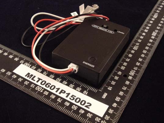
Click to zoom
Application Details
- Equipment Class
- CRR - Superregenerative Receiver
- Date of Grant
- Feb 09, 2006
- Application Purpose
- Original Equipment
- Date of Application
- Feb 09, 2006
- Equipment Note
- RECEIVER
- Frequency Range
- 303.80000000 - 303.80000000
- Company
- Skytech II, Inc.
- Country
- United States
Documents & Files
Document Text
Text extracted from the exhibit documents filed with the FCC. Open a document above to read the original.
Users Manual
REMOTE RECEIVER The remote receiver operates on power from the thermopile. It is recommended that the thermopile voltage with the main burner OFF be no less than 450 millivolts for proper microprocessor performance. IMPORTANT: It is essential that proper voltage from the thermopile be maintained for proper operation of the remote receiver. The remote receiver houses the microprocessor that responds to commands from the transmitter to control system operation. It emits one beep when it receives an ON or OFF command manually, but no beep when cycling on and off automatically in THERMO mode. The remote receiver has a 3-position slide switch for selecting the MODE of operation: ON/REMOTE/OFF • With the slide switch in the ON position (toward the LEARN button), the system will remain on until the slide switch is placed in the OFF or REMOTE position. • With the slide switch in the REMOTE position (centered), the system will only operate if the remote receiver receives commands from the transmitter. • With the slide switch in the OFF position (away from the LEARN button), the system is off. • It is suggested that the slide switch be placed in the off position if you will be away from your home for an extended period of time. If the remote receiver is mounted out of children’s reach, placing the slide switch in the OFF position also functions as a safety “lock-out” by both turning the system off and rendering the remote receiver inoperative. THERMO- SAFETY FEATURE – RECEIVER (T/S –RX) This SKYTECH remote control has a THERMO- SAFETY feature that is built into the system’s RECEIVER. This feature is temperature- activated and provides an extra margin of safety when the RECEIVER is operating where ambient temperatures exceed 160 °F degrees inside the receiver case. The THERMO-SAFETY feature, in the RECEIVER, operates in the following manner, when the appliance is in operation. The receiver is thermally protected from extreme heat conditions. Heat can have negative effect on the operation of the receiver’s microprocessors. When the ambient temperature at the THERMISTOR, inside the receiver case, reaches 160°F, the THERMISTOR will automatically shut the appliance down and the RECEIVER will begin emitting a series of 2 “beeps”, every 4 seconds. When the ambient temperature, at the RECEIVER, drops between 150°F and 160 °F, the user can reactivate the appliance by pushing the MODE button on the transmitter. The word ON must display on the LCD screen. When the MODE button is pressed to ON, the THERMISTOR “resets” itself and the fireplace will begin operating again. However, the “beeping” will continue, if the ambient temperature remains between 150°F and 160°F. This “beeping” alerts the user that the RECEIVER should be repositioned so the ambient temperature drops below 150°F. When the temperature drops below 150°F, the “beeping” will cease, providing the user has “reset” the THERMISTOR by pushing the MODE button to ON to operate the appliance, either manually or thermally. Allow sufficient time for the receiver to cool below 150°F, and then press MODE button to stop beeping. INSTALLATION INSTRUCTIONS WARNING This remote control system must be installed exactly as outlined in these instructions. Read all instructions completely before attempting installation. Follow instructions carefully during installation. Any modifications of the SKYTECH remote control or any of its components will void the warranty and may be pose a fire hazard. Do not connect any gas valve to 110-120VAC power. Consult gas appliance manufacturer’s instructions and wiring schematics for proper placement of all wires. The following wiring diagrams are for illustration purpose only. Follow instructions from manufacturer of gas valve and/or electronic module for correct wiring procedures. Improper installation of electric components can cause damage to electronic gas valve and remote receiver. HEARTH MOUNT INSTALLATION The remote receiver is be placed on the fireplace hearth or under the fireplace, behind the control access panel due to the connections to the TH, TP, & TH/TP terminals on the gas valve. PROTECTION FROM EXTREME HEAT IS VERY IMPORTANT. Position where the ambient temperature inside the receiver case does not exceed 160°F. NOTE: The remote receiver will only respond to the transmitter when the 3-position slide button on the remote receiver is in the REMOTE position. If the system does not respond to the battery transmitter on initial use, see MATCHING SECURITY CODES. WIRING INSTRUCTIONS A qualified electrician or a gas technician who is familiar with the gas appliance and gas valves that will be operated by this remote should install the remote control system. Incorrect wiring connections WILL cause damage to the gas valve and may also damage the remote receiver. WIRING MILLIVOLT VALVES ONLY (WILL NOT OPERATE ON ELECTRONIC SPARK IGNITION SYSTEMS) The remote receiver is connected to the TH, TP, & TH/TP terminals on the millivolt gas valve. Connect the (3) 18” gauge stranded wires from the remote receiver to the gas valve. These (3) wires are marked TH, (Black Wire) TP, (Red Wire) and TH/TP (White Wire) Note: The RED wire from the thermopile must match up with the RED wire from the 3301BE on the (TP) terminal of the gas valve. The WHITE/YELLOW wire from the thermopile must match up with the WHITE wire from the 3301BE on the (TH/TP) terminal of the gas valve. The reason for this is the 3301BE is polarity based. These changes will make the gas valve and the thermopile match the 3301BE. Operation of the remote receiver is similar to that of a thermostat in that both turn the gas valve on and off based on input signals. A thermostat’s input signals are different temperatures. The remote receiver’s input signals come from the transmitter. Connect each of the three (3) wires leading from the receiver to the TH, TP, and TH/TP terminals on the millivolt gas. These (3) wires are marked TH, (Black Wire) TP, (Red Wire) and TH/TP (White W…
Text truncated - open the document above for the full version.
Block Diagram
BE Block Chart Thermo Pilot Energize Energize Key Power Supply RF Signal Receiver Controller Driver
External Photos
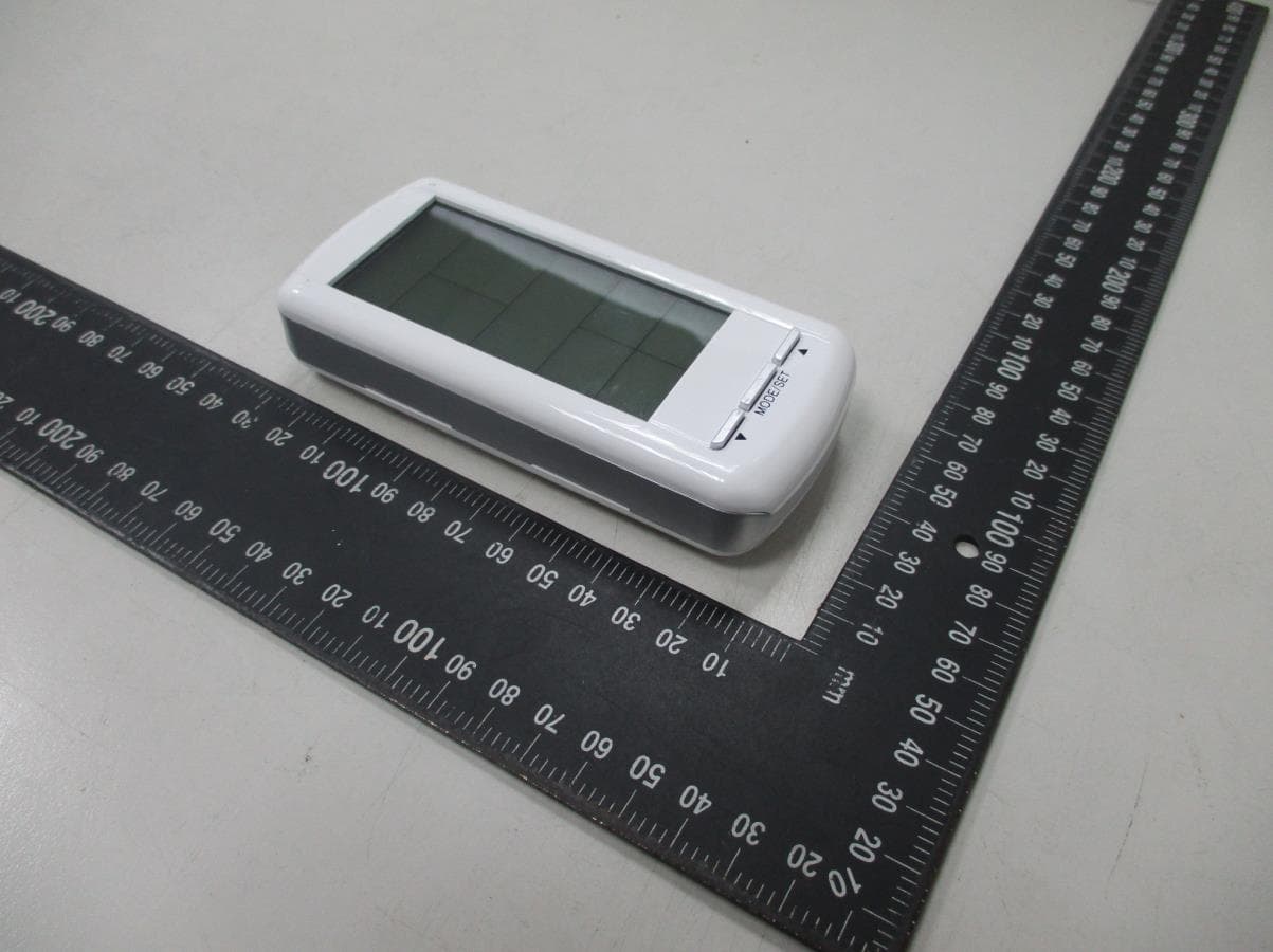
MAX LIGHT Technology Lab MAX LIGHT Technology Lab
ID Label/Location Info
Technology Lab Label Format: Label Position: Equipment Label 2.0cmX1.0cm Rear View This device complies with Part 15 of the FCC Rules. Operation is subject to the following two conditions: (1) This device may not cause harmful interference, and (2) This device must accept any interference received, including. Interference that may cause undesired operation. Model No: 3301BE FCC ID: K9L3301BE
Internal Photos
MAX LIGHT Technology Lab MAX LIGHT Technology Lab MAX LIGHT Technology Lab
Operational Description
1. System supply by battery and MCU control this system 2. There are one switch for user select control by manual or remote 3. Receiver when control by remote it output status same as remote display. 4. There are two output one is dry contact another is fan speed control. 5. Temperature sensor sense the environment temperature when temperature too high receiver will cut off all output.
Schematics
1 2 3 4 56 ABCD 6 5 4 3 2 1 D CBA Title Number Revision Size B Date: 12-Jan-2006 Sheet of File: \\..\BE.sch Drawn By: IN I GND G OUT O U4HT1034 + EC2 4.7uF/10V C1103 R347K L2 L1 MD-0417 C22P7 T1 MMBR941B C3221 C4102 C5104 R44.7K R510M C6 15P C7104 C8 30P R6 10M C9104 R72MR84.7M 1 2 3 4 8 7 6 5 SW1 922-SIC-23P + EC3 33u/16V BATT 12 SWETB1102 C17104 R17510K R1610M T.SW SW-PB BZBUZZER VDD VDD VCC VRF VRF VSS VSS VSS VSS VSS COM1 COM2 R15 330R BC2032E 2003/07/11 RB0 RA2RA1RA0 VCC RB4 RB3 3 4 U1B4069 5 6 U1C 4069 13 12 U1F 4069 11 10 U1E 4069 R10R VDD VDD +6V GND N14 N21 VDD N26 ANTENNA C16104 RT1503R13100K C15474 VCC R251R VRF SKY 1001P/1002P/1001/3001 rx Q1C2412 C11104 R11100K X176.8K C922PC1022P VCC VCC RA2 1 RA3 2 RTCC 3 RST 4 VSS 5 RB0 6 RB1 7 RB2 8 RB3 9 RB4 10 RB5 11 RB6 12 RB7 13 VDD 14 XT2 15 XT1 16 RA0 17 RA1 18 U3EM78156(SMD) C12104 D2 1N4148 N18 GND N20 GND GND RB0 RB6RB5 RB3 N29 +6V RB2 RB4 RA2 RA1RA0 RB7 RB2 CS 1 CLK 2 DI 3 DO 4 VSS 5 VCC 8 U293LC46 T2 IRF-530A T3IRF-530A RA3 1 TEST 1 T2 1 T3 1 T4 1 T5 1 T6 1 T9 1 T10 1 T11 1 T12 L3 RA3 N14N15N16N19N42 N42N20 N31 N40 N30 N20N21N22N23 N24N25 N26N27 N24N25 N14N27 N19 N41 VCC N2 N3 N4 N5 N8 N9 N10 N11 N12 EC1 4.7uF/10V C19104 VRF VCC C18104 VSS R140R R240R N46 N47 9 8 U1D4069 1 2 U1A4069 VCC 12 SEL1 ON:3 1short;6 8shortAUTO:3 2short;6 7shortOFF:3 4short;6 5short Q4IRLML2402 Q5IRLML2402 Q6MMBF4392 C10.47u C200.47u C210.47u R101K R91K SW2SW 1 2 3 VR11MR GND+6V GND 12 3 D4BAT54S 12 3 D3BAT54S 2 3 4 1 5 TR1TR Q2_G Q1_G Q1_G N3 D2_3 D3_3 Q3_G GND N1 N2 Q2_D Q1_D N3 N3 Q3_SGND 1 2 3 D1BAT54S TP VOUT VIN 1 8 isolation2 7 isolation3 6 isolation4 5 isolation EC4100u/16V ZD16.2V
Test Report
Product : Receiver Applicant : Skytech II, Inc. FCC ID : K9L3301BE Trade Name : SKYTECH II Model No. : 3301BE (See Appendix II) Report No. : MLT0601P15002 Issue Date : Jan 18, 2006 Test By Max Light Technology Co., Ltd. Room 5, 8F, No.125, Section 3 Roosevelt Road, Taipei, Taiwan, R.O.C. Tel: 886-2-2363-2447 Fax: 886-2-2363-2597 T T h h e e t t e e s s t t r r e e p p o o r r t t c c o o n n s s i i s s t t s s o o f f 1 1 6 6 p p a a g g e e s s i i n n t t o o t t a a l l . . I I t t m m a a y y b b e e d d u u p p l l i i c c a a t t e e d d c c o o m m p p l l e e t t e e l l y y f f o o r r l l e e g g a a l l u u s s e e w w i i t t h h t t h h e e a a l l l l o o w w a a n n c c e e o o f f t t h h e e a a p p p p l l i i c c a a n n t t . . I I t t s s h h a a l l l l n n o o t t b b e e r r e e p p r r o o d d u u c c e e d d e e x x c c e e p p t t i i n n f f u u l l l l , , w w i i t t h h o o u u t t t t h h e e w w r r i i t t t t e e n n a a p p p p r r o o v v a a l l o o f f o o u u r r l l a a b b o o r r a a t t o o r r y y . . MAX LIGHT MEASUREMENT REPORT Page: 2/16 Report Number: MLT0601P15002 FCC ID: K9L3301BE Technology Lab Table of Contents : I. General 4. II. Conducted Emissions Requirements 7. III. Radiated Emissions Requirements 8. Appendix I (EUT Test Setup) 14. Appendix II (Model No.) 16. MAX LIGHT MEASUREMENT REPORT Page: 3/16 Report Number: MLT0601P15002 FCC ID: K9L3301BE Technology Lab CERIFICATION We here by verify that : The test data, data evaluation, test procedures and equipment configurations shown in this report were made in accordance with the procedures given in ANSI C63.4: 2003. All test were conducted by MLT (Max Light Technology Co., Ltd) Room 5, 8F, No.125, Section 3 Roosevelt Road, Taipei, Taiwan, R.O.C Also, we attest to the accuracy of each. We further submit that the energy emitted by the sample EUT tested as described in the report is in compliance with Class B radiated and conducted emission limit of FCC Rules Part 15 Subpart B. EUT : Receiver Applicant : Skytech II, Inc. 9230 Conservation Way, Ft. Wayne, IN 46809, U.S.A. Manufacturer : FEGO Precision Industrial Co.,Ltd 947 LIN SEN RD.,WU-FENG SHIANG TAICHUNG HSIEN R.O.C. Model No : 3301BE (See Appendix II) FCC ID : K9L3301BE Prepared by : Approved by : Jesse Tien Roger Chen MAX LIGHT MEASUREMENT REPORT Page: 4/16 Report Number: MLT0601P15002 FCC ID: K9L3301BE Technology Lab I. GENERAL 1.1 Introduction The following measurement report is submitted on behalf of SKYTECH II INC. In support of a Class B Device Certification in accordance with Part2 Subpart J and Part 15 Subpart A And B of the Commission’s and Regulations. The test data, data evaluation, test procedures and equipment configurations shown in this report were made in accordance with the procedures given in ANSI C63.4: 2003. ANSI STANDARD C63.4- 2003 SUPER REGENERATIVE RECEIVER: A signal generator was set to the unit under test operating frequency. An un- modulated continuous wave (CW) signal was radiated at the super- regenerative receiver operating frequency to cohere the characteristic broadband emissions from the receiver. EUT : Receiver Applicant : Skytech II, Inc. 9230 Conservation Way, Ft. Wayne, IN 46809, U.S.A. Manufacturer : FEGO Precision Industrial Co. Ltd 947 LIN SEN RD., WU-FENG SHIANG TAICHUNG HSIEN R.O.C. Model No : 3301BE (See Appendix II) FCC ID : K9L3301BE Power Type : Power By DC 0.45V During testing the EUT was operated at Testing mode for each emission measured. This was done in order to ensure that maximum emission levels were attained. MAX LIGHT MEASUREMENT REPORT Page: 5/16 Report Number: MLT0601P15002 FCC ID: K9L3301BE Technology Lab 1.2 Description of Support Equipment In order to construct the minimum system which required by the ANSI C63.4: 2003, following equipments were used as the support units. The Receiver itself forms a system. No support equipment is required for its normal operation. 1.3 Configuration of System Under Test During testing the EUT (Receiver)’s was connected to DC power supply, the other Port’s cable was connected to LED and battery box circuit. When the EUT was “ON”, the LED was lighting. DC Power Supply EUT Battery Box (3Vdcx) LED MAX LIGHT MEASUREMENT REPORT Page: 6/16 Report Number: MLT0601P15002 FCC ID: K9L3301BE Technology Lab 1.4 Test Procedure All measurements contained in this report were performed according to the techniques described in Measurement procedure ANSI C63.4-2003 "Measurement of unIntentional Radiators." 1.5 General Test Condition The conditions under which the EUT operates were varied to determine their effect on the equipment's emission characteristics. The final configuration of the test system and the mode of operation used during these tests were chosen as that which produced the highest emission levels. However, only those conditions which the EUT was considered likely to encounter in normal use were investigated. The system's radiated and conducted emissions were investigated while the EUT keep operating ON and OFF mode by receiving signals from transmitter. The system's physical layout and cabling was randomly arranged to ensure that maximum emission levels were attained. MAX LIGHT MEASUREMENT REPORT Page: 7/16 Report Number: MLT0601P15002 FCC ID: K9L3301BE Technology Lab II. Conducted Emissions Requirements The EUT operates solely by the DC power supply. According to the rule of Section 15.207(c), the EUT exempt to the power line conducted test. MAX LIGHT MEASUREMENT REPORT Page: 8/16 Report Number: MLT0601P15002 FCC ID: K9L3301BE Technology Lab III. Radiated Emissions Requirements 3.1 General & Setup : Prior to open-field testing, the EUT was placed in a shielded enclosure and scanned at a close distance to determine its emission characteristics. The physical arrangement of the EUT was varied (within the scope of arrangements likely to be encountered in actual use) to determine the effect on the unit's emanations in amplitude, directivity, and freq…
Text truncated - open the document above for the full version.
Test Setup Photos
MAX LIGHT MEASUREMENT REPORT Page: 9/16 Report Number: MLT0601P15002 FCC ID: K9L3301BE Technology Lab 3.3 Test Configuration: Front View of The Test Configuration MAX LIGHT MEASUREMENT REPORT Page: 10/16 Report Number: MLT0601P15002 FCC ID: K9L3301BE Technology Lab Rear View of The Test Configuration
Contact Information
Applicant
Vincent Onaji(Engineering Project Manager)
Test Firm
Max Light Technology Co., Ltd.Jesse Tien
Technical Specifications
| # | Rule Parts | Frequency Range | Power Output |
|---|---|---|---|
| 1 | 15B | 303.8 MHz - 303.8 MHz | - |
Other Applications from Skytech II, Inc.
K9LAFTS3TX
Jul 17, 2022Remote control transmitter
Equipment Class
DSC - Part 15 Security/Remote Control TransmitterK9L8001TX
Jun 05, 2021Remote Control Transmitter
Equipment Class
DSC - Part 15 Security/Remote Control Transmitter
K9L-4001THATX
Apr 22, 2020Wireless Remote Controller (TX)
Equipment Class
DSC - Part 15 Security/Remote Control TransmitterK9L3001-1TX
Feb 18, 2020Remote Control
Equipment Class
DSC - Part 15 Security/Remote Control Transmitter
K9LREMOTION
Jul 16, 2013Transmiter
Equipment Class
DTS - Digital Transmission System