K9L3301PFRECEIVER
Skytech II, Inc.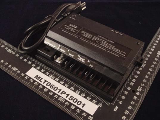
Click to zoom
Application Details
- Equipment Class
- CRR - Superregenerative Receiver
- Date of Grant
- Jan 26, 2006
- Application Purpose
- Original Equipment
- Date of Application
- Jan 26, 2006
- Equipment Note
- RECEIVER
- Frequency Range
- 303.80000000 - 303.80000000
- Company
- Skytech II, Inc.
- Country
- United States
Documents & Files
Document Text
Text extracted from the exhibit documents filed with the FCC. Open a document above to read the original.
Users Manual
1/3 3301PF RX function description 2/3 3/3
Block Diagram
3301PF Receiver Function block Electricity Power Input VA LV E FAN Manual switch RF receive module MCU Temperature sense circuit EEPROM
External Photos
MAX LIGHT Technology Lab MAX LIGHT Technology Lab
ID Label/Location Info
Technology Lab Label Format: Label Position: Equipment Label 2.0cmX1.0cm Rear View This device complies with Part 15 of the FCC Rules. Operation is subject to the following two conditions: (1) This device may not cause harmful interference, and (2) This device must accept any interference received, including. Interference that may cause undesired operation. Model No: 3301PF FCC ID: K9L3301PF
Internal Photos
MAX LIGHT Technology Lab MAX LIGHT Technology Lab MAX LIGHT Technology Lab MAX LIGHT Technology Lab MAX LIGHT Technology Lab
Operational Description
3301PF Receiver theory Electricity Power Input VA LV E FAN Manual switch RF receive module MCU Temperature sense circuit EEPROM 1. System supply by battery and MCU control this system 2. There are one switch for user select control by manual or remote 3. Receiver when control by remote it output status same as remote display. 4. There are two output one is dry contact another is fan speed control. 5. Temperature sensor sense the environment temperature when temperature too high receiver will cut off all output.
Schematics
123456 A B C D 654321 D C B A Title NumberRevisionSize B Date:18-Jan-2006Sheet of File:D:\BeenNan\..\Bc-9024-V1.schDrawn By: 1 AC-L 1 AC-N 1 FAN1 1 FAN2 1 Valve 1 1 Valve 2 1 Amber1 1 Amber2 Q1 C945 Q2 C945 X1 4MZ BC-9024 (3001PM) E1 470uF/35V E3 220uF/10V C1 104 C5 104 C4 104 C2 104 E4 220uF/10V D3 IN4148 D2 IN4148 RY1 DC 24V RY2 DC 24V R1 10R R3 10K R4 680 R5 10K R7 1K R8 1K Vin 1 GND 2 +5V 3 U1 78L05 PA2 1 PA3 2 RTCC 3 RST 4 VSS 5 RB0 6 RB1 7 RB2 8 RB3 9 RB4 10 RB5 11 RB6 12 RB7 13 VDD 14 XT2 15 XT1 16 RA0 17 RA1 18 U3 EM 78156 CS 1 CLK 2 DI 3 DO 4 VSS 5 VCC 8 U5 93C46 T.SW ANTGNDGNDVCCVCCTEOUTGND RF RF REV R2 10R +5V VDD VDD VDD +24V +24V +24V VDD VDD +5V BZ BZ SW SW-DPDT-1 RB5 RB3 VL2 VL2 VL1 VL1 RB5 RB3 ON ON OFF OFF REMOTE Learning RB1 PA3 N1 N2 N3 RY3 DC 24V R10 1K Q3 C945 D5 IN418 +24V +24V +24V +24V +24V GND VDD TR1 24V 89/04/29 1 GND Q4 C945 D4 IN4148 RY4 DC 24V R9 1K +24V RB2 AC-N AC-L +24V Fan LED5 Valve LED1 Amber LED3 123 AC AC SOCKET IN 1 GND 2 OUT 3 U4 HT-7033A +5V N6 N7 N8 N6 N7 N2 N1 N0 N0 RB2 VDD VDD E5 220uF/10V C3 104 R6 10R Vin 1 GND 2 +5V 3 U2 78L05 VDD VDD GND N8 VSS GND VSS VSS VSS E2 470uF/35V D6 IN4004 1 Flame1 1 Flame2 Q5 C945 R11 1K VDD RB4 +5V RB1 RF IN RF OUT GND RY5 DC 24V Flame LED2 AUX LED4 1 AUX2 1 AUX1 +24V BR1 BR154 D1 IN4004 BR4 (8A) (8A) (1A) N4 N5 N6 N9 N10N10 N11 N12N13 N14 N15 N16 N17 N18 N19 N21 N21 N22 N23 N24 N25 N15 N16 N17N18 N19 N26N27 N28 N29N30 N31N32 N33 N34N35 N36 N37N38 N39N40 N41 N42N43 N44N45 N46 N47N48 N49 RB7 R12 100K R13 503T C6 104 VDD N50 N12 RB7 C7 5P/1KV R14 10K FUSE 3A/125V N51 1 W(L) 1 W(L) 1 FAN(L) 1 FAN(N) ANT ANTENNA NO USED
Test Report
Product : Receiver Applicant : Skytech II, Inc. FCC ID : K9L3301PF Trade Name : SKYTECH II Model No. : 3301PF (See Appendix II) Report No. : MLT0601P15001 Issue Date : Jan 18, 2006 Test By Max Light Technology Co., Ltd. Room 5, 8F, No.125, Section 3 Roosevelt Road, Taipei, Taiwan, R.O.C. Tel: 886-2-2363-2447 Fax: 886-2-2363-2597 T T h h e e t t e e s s t t r r e e p p o o r r t t c c o o n n s s i i s s t t s s o o f f 2 2 0 0 p p a a g g e e s s i i n n t t o o t t a a l l . . I I t t m m a a y y b b e e d d u u p p l l i i c c a a t t e e d d c c o o m m p p l l e e t t e e l l y y f f o o r r l l e e g g a a l l u u s s e e w w i i t t h h t t h h e e a a l l l l o o w w a a n n c c e e o o f f t t h h e e a a p p p p l l i i c c a a n n t t . . I I t t s s h h a a l l l l n n o o t t b b e e r r e e p p r r o o d d u u c c e e d d e e x x c c e e p p t t i i n n f f u u l l l l , , w w i i t t h h o o u u t t t t h h e e w w r r i i t t t t e e n n a a p p p p r r o o v v a a l l o o f f o o u u r r l l a a b b o o r r a a t t o o r r y y . . MAX LIGHT MEASUREMENT REPORT Page: 2/20 Report Number: MLT0601P15001 FCC ID: K9L3301PF Technology Lab Table of Contents : I. General 4. II. Conducted Emissions Requirements 7. III. Radiated Emissions Requirements 12. Appendix I (EUT Test Setup) 18. Appendix II (Model No.) 20. MAX LIGHT MEASUREMENT REPORT Page: 3/20 Report Number: MLT0601P15001 FCC ID: K9L3301PF Technology Lab CERIFICATION We here by verify that : The test data, data evaluation, test procedures and equipment configurations shown in this report were made in accordance with the procedures given in ANSI C63.4: 2003. All test were conducted by MLT (Max Light Technology Co., Ltd) Room 5, 8F, No.125, Section 3 Roosevelt Road, Taipei, Taiwan, R.O.C Also, we attest to the accuracy of each. We further submit that the energy emitted by the sample EUT tested as described in the report is in compliance with Class B radiated and conducted emission limit of FCC Rules Part 15 Subpart B. EUT : Receiver Applicant : Skytech II, Inc. 9230 Conservation Way, Ft. Wayne, IN 46809, U.S.A. Manufacturer : FEGO Precision Industrial Co.,Ltd 947 LIN SEN RD.,WU-FENG SHIANG TAICHUNG HSIEN R.O.C. Model No : 3301PF (See Appendix II) FCC ID : K9L3301PF Prepared by : Approved by : Jesse Tien Roger Chen MAX LIGHT MEASUREMENT REPORT Page: 4/20 Report Number: MLT0601P15001 FCC ID: K9L3301PF Technology Lab I. GENERAL 1.1 Introduction The following measurement report is submitted on behalf of SKYTECH II INC. In support of a Class B Device Certification in accordance with Part2 Subpart J and Part 15 Subpart A And B of the Commission’s and Regulations. The test data, data evaluation, test procedures and equipment configurations shown in this report were made in accordance with the procedures given in ANSI C63.4: 2003. ANSI STANDARD C63.4- 2003 SUPER REGENERATIVE RECEIVER: A signal generator was set to the unit under test operating frequency. An un- modulated continuous wave (CW) signal was radiated at the super- regenerative receiver operating frequency to cohere the characteristic broadband emissions from the receiver. EUT : Receiver Applicant : Skytech II, Inc. 9230 Conservation Way, Ft. Wayne, IN 46809, U.S.A. Manufacturer : FEGO Precision Industrial Co. Ltd 947 LIN SEN RD., WU-FENG SHIANG TAICHUNG HSIEN R.O.C. Model No : 3301PF (See Appendix II) FCC ID : K9L3301PF Power Type : Power By AC 120V / 60Hz During testing the EUT was operated at Testing mode for each emission measured. This was done in order to ensure that maximum emission levels were attained. MAX LIGHT MEASUREMENT REPORT Page: 5/20 Report Number: MLT0601P15001 FCC ID: K9L3301PF Technology Lab 1.2 Description of Support Equipment In order to construct the minimum system which required by the ANSI C63.4: 2003, following equipments were used as the support units. The Receiver itself forms a system. No support equipment is required for its normal operation. 1.3 Configuration of System Under Test During testing the EUT (Receiver)’s one cable was connected to Light bulb, the other Port’s cable was connected to LED and battery box circuit. When the EUT was “ON”, the LED and light bulb were lighting. Power Supply EUT Battery Box (3Vdcx) LED Light LED MAX LIGHT MEASUREMENT REPORT Page: 6/20 Report Number: MLT0601P15001 FCC ID: K9L3301PF Technology Lab 1.4 Test Procedure All measurements contained in this report were performed according to the techniques described in Measurement procedure ANSI C63.4-2003 "Measurement of unIntentional Radiators." 1.5 General Test Condition The conditions under which the EUT operates were varied to determine their effect on the equipment's emission characteristics. The final configuration of the test system and the mode of operation used during these tests were chosen as that which produced the highest emission levels. However, only those conditions which the EUT was considered likely to encounter in normal use were investigated. The system's radiated and conducted emissions were investigated while the EUT keep operating ON and OFF mode by receiving signals from transmitter. The system's physical layout and cabling was randomly arranged to ensure that maximum emission levels were attained. MAX LIGHT MEASUREMENT REPORT Page: 7/20 Report Number: MLT0601P15001 FCC ID: K9L3301PF Technology Lab II. Conducted Emissions Requirements 2.1 General & Setup : The power line conducted emission measurements were performed in a shielded enclosure. The EUT was assembled on a wooden table which is 80 centimeters high, was placed 40 centimeters from the back wall and at least 1 meter from the sidewall. Power was fed to the EUT from the public utility power grid through a line filter and EMCO Model 3825/2 Line Impedance Stabilization Networks (LISN). The LISN housing, measuring instrumentation case, ground plane, etc., were electrically bonded together at the same RF potential. The Spectrum analyzer was connected to the AC line through an isolation tra…
Text truncated - open the document above for the full version.
Test Setup Photos
MAX LIGHT MEASUREMENT REPORT Page: 13/20 Report Number: MLT0601P15001 FCC ID: K9L3301PF Technology Lab 3.3 Test Configuration: Front View of The Test Configuration MAX LIGHT MEASUREMENT REPORT Page: 14/20 Report Number: MLT0601P15001 FCC ID: K9L3301PF Technology Lab Rear View of The Test Configuration
Contact Information
Applicant
Vincent Onaji(Engineering Project Manager)
Test Firm
Max Light Technology Co., Ltd.Jesse Tien
Technical Specifications
| # | Rule Parts | Frequency Range | Power Output |
|---|---|---|---|
| 1 | 15B | 303.8 MHz - 303.8 MHz | - |
Other Applications from Skytech II, Inc.
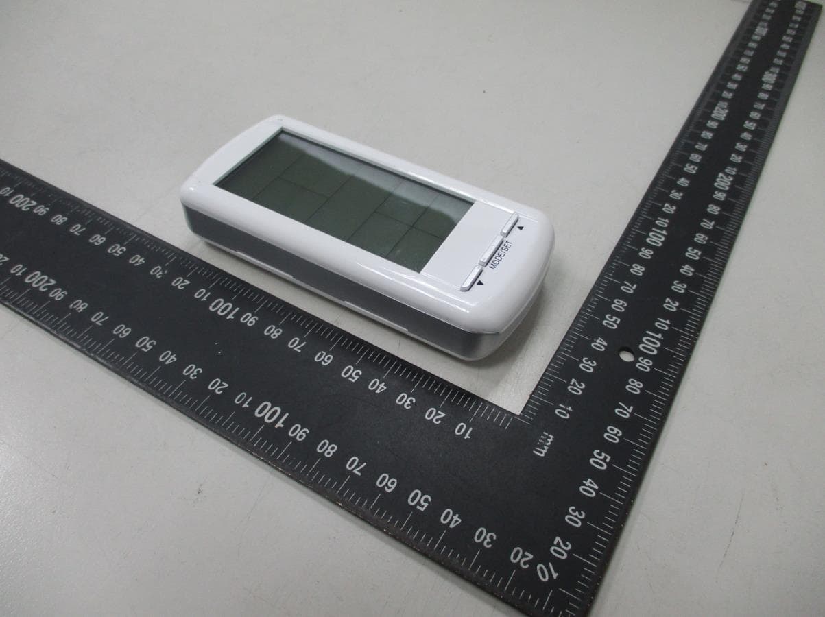
K9LAFTS3TX
Jul 17, 2022Remote control transmitter
Equipment Class
DSC - Part 15 Security/Remote Control TransmitterK9L8001TX
Jun 05, 2021Remote Control Transmitter
Equipment Class
DSC - Part 15 Security/Remote Control Transmitter
K9L-4001THATX
Apr 22, 2020Wireless Remote Controller (TX)
Equipment Class
DSC - Part 15 Security/Remote Control TransmitterK9L3001-1TX
Feb 18, 2020Remote Control
Equipment Class
DSC - Part 15 Security/Remote Control Transmitter
K9LREMOTION
Jul 16, 2013Transmiter
Equipment Class
DTS - Digital Transmission System