K9L3301TXRemote Control Transmitter
Skytech II, Inc.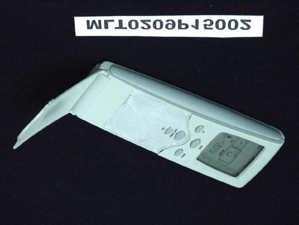
Click to zoom
Application Details
- Equipment Class
- DSC - Part 15 Security/Remote Control Transmitter
- Date of Grant
- Oct 02, 2002
- Application Purpose
- Original Equipment
- Date of Application
- Oct 02, 2002
- Equipment Note
- Remote Control Transmitter
- Frequency Range
- 303.20000000 - 303.20000000
- Company
- Skytech II, Inc.
- Country
- United States
Documents & Files
Document Text
Text extracted from the exhibit documents filed with the FCC. Open a document above to read the original.
Users Manual
Skytech 3001 REV 12/01 Page 1 of 8 3301 INSTALLATION AND OPERATING INSTRUCTIONS INTRODUCTION This SKYTECH remote control system was developed to provide a safe, reliable, and user-friendly remote control system for gas heating appliances. The system can be operated thermostatically or manually from the transmitter. The system operates on radio frequencies (RF) within a 20'’range using non-directional signals. The system operates one of 1,048,576 security codes that are programmed into the transmitter at the factory; the remote receiver’s code must be matched to that of the transmitter prior to initial use. The transmitter operates on 2 AAA-size 1.5V batteries. It is recommended that ALKALINE batteries always be used for longer battery life and maximum operational performance. IMPORTANT : New or fully charged batteries are essential for proper operation of the multi- function transmitter. Insert 2 AAA-size 1.5 V batteries into the battery compartment on the back of the transmitter, positioning the (+) and (-) ends of the batteries as indicated on the casing. When the batteries are inserted, the screen at right (with similar numbers) will display. Note: If a LOW battery icon appears on the screen, check the position of the batteries; a reversed battery will activate the LOW battery icon. Note: Due to the sensitive temperature-monitoring components in the transmitter, it may be necessary to allow the transmitter to stabilize to room temperature before accurate room temperatures are displayed on the screen. If the transmitter is activated from a severe cold condition, it can take up to fifteen minutes for accurate temperature readings to appear. 1. LOW - Battery power is low. Replace batteries within two weeks. 2. TIMER- Indicates time remaining before system shuts off, when timer-programmed; 9-hour maximum setting. 3. MODE - Indicates operation MODE of system. ON indicates the system is on, either manually or thermostatically. OFF indicates the entire system is turned off..THERMO indicates the system will automatically cycle on/off, depending on programmed 4. SET - Indicates desire SET room temperature for THERMO operation 5. FLAME – Indicates burner/valve in operation. 6. CLOCK – Indicates the current time in AM/PM 7. ROOM – Indicates CURRENT room temperature. 8. 0 F indicates degrees Fahrenheit ( 0 C indicates degrees Celsius). FUNCTIONS To operate the system, press the MODE button on the front of the transmitter to select the operational MODE desired. • ON indicates the system is on, either manually, timed or thermostatically. • THERMO indicates the system will automatically cycle ON/OFF, depending • on programmed set temperature. • OFF indicates the entire system is turned off. Review COMMUNICATION SAFETY SECTION under TRANSMITTER section and THERMO SAFETY SECTION under REMOTE RECEIVER section. These signal/temperature safety features shut down the fireplace system when a potentially unsafe condition exists. TRANSMITTER Cover Closed UPDOWN MODE UPDOWN MODE TIMER TIME SET Cover Open ROOM OFF SET PM LCD DISPLAY Skytech 3001 REV 12/01 Page 2 of 8 Flip down the plastic cover on the front of the transmitter to expose the “SET” buttons. The flip cover protects the SET buttons from being changed accidentally. Close the cover after completing the following settings/programming. Flashing numbers on the display indicate the system is awaiting user input, such as using the UP and DOWN buttons to program a new setting. If no change is made to flashing digits within 15 seconds, the system will complete the procedure last programmed and reset the display to its normal state. 1. Press and hold the TIMER/TIME button on the transmitter for more than two seconds. The hour digit(s) will begin flashing. 2. Press the UP or DOWN button until the desired hour is displayed in AM or PM. 3. After setting the desired hour, press and release the TIMER/TIME button again to set the minutes; the minute digits will begin flashing. 4. Press the UP or DOWN button until the desired minutes are displayed. 5. Press and hold the TIMER/TIME button again for more than two seconds. The time digits will cease flashing, indicating the clock has been successfully set. You may also press the SET button on the transmitter to stop the time digits from flashing and set the time. SETTING 0 F / 0 C SCALE The factory setting for temperature is 0 F . To change this setting to 0 C, first press and hold the UP button and the DOWN button on the transmitter at the same time. Follow this same procedure to change from 0 C back to 0 F . When changing between the 0 F and 0 C scales, the temperature in the SET frame defaults to the lowest temperature (45 0 F , or 6 0 C ). The highest SET temperature is 99 0 Fahrenheit (32 0 Celsius ). SETTING DESIRED ROOM TEMPERATURE This remote control system can be thermostatically controlled when the transmitter is in the THERMO mode ( THERMO must be displayed on the screen). To set the DESIRED room temperature, press the MODE button to place the transmitter into THERMO mode, then press the UP or DOWN button to select the desired room temperature. The highest SET temperature is 99 0 Fahrenheit (32 0 Celsius ). OPERATIONAL NOTE: TO CONSERVE BATTERY POWER, CHANGES IN ROOM TEMPERATURE ARE AUTOMATICALLY UPDATED EVERY TWO MINUTES TO THE TRANSMITTER. The Thermo Mode on the transmitter operates the appliance whenever the ROOM TEMPERATURE varies a certain number of degrees from the SET TEMPERATURE. This variation is called the “SWING” or TEMPERATURE DIFFERENTIAL. The normal operating cycle of an appliance may be 2-4 times per hour depending on how well the room or home is insulated from the cold or drafts. A smaller “swing number” increases the number of cycles so the room temperature is more constant. A larger “swing number” decreases the number of cycles, which saves energy, in most cases. The factory setting for the “swing number” is 2. This represents a temperature variation of +/- 2 0 F (1 0 C) between SET temper…
Text truncated - open the document above for the full version.
Block Diagram
1 2 3 4 56 ABCD 6 5 4 3 2 1 D CBA Title Number Revision Size B Date: 17-Sep-2002 Sheet of File: C:\WINDOWS\..\proced ure.sch Drawn By: MCU. Key input Temperature Lcd Driver Set timer RF output & clock Lcd display Procedure
External Photos
MAX LIGHT Report Number: MLT0209P15002 FCC ID: K9L3301TX Technology Lab MAX LIGHT Report Number: MLT0209P15002 FCC ID: K9L3301TX Technology Lab
ID Label/Location Info
MAX LIGHT Report Number: MLT0209P15002 FCC ID: K9L3301TX Technology Lab Label Format: Label Position: This device complies with Part15 of the FCC Rules. Operation is subject to the following two conditions: (1) This device may not cause harmful interference,and (2) This device must accept any interference received ,including. Interference that may cause undesired operation. Model : SKY-3301 , SKY-3301P , SKY-3301PF SKY-3324PM , SKY-3324R , SKY-3324RM FCC ID : K9L3301TX Equipment Lable 4.0cmX2.5cm Rear View
Internal Photos
MAX LIGHT Report Number: MLT0209P15002 FCC ID: K9L3301TX Technology Lab MAX LIGHT Report Number: MLT0209P15002 FCC ID: K9L3301TX Technology Lab
Operational Description
Skytech 3301 Remote 1. Rf signal is generated by micro controller unit: EM78P257A. It sent a series of pulse to RF circuit. 2. RF circuit is use RLC oscillator with capacitor variable. 3. When MCU. sent signal to RF circuit,the RLC will occur ASK format signal to antenna. 4. There are 3 models of Skytech 3301,Æ 7,8,9 keys, and the main functions of key are : Mode,Set,Timer,Up,Down, others are combined keys as degree transform,Backlight set,and Swing. 5. There are over 7 kinds codes in different keys.
Operational Description
Changing timer below(U4 EM78P257A) : Duration Time : 670 mini-second Less than 1 second.
Schematics
123456 A B C D 654321 D C B A Title NumberRevisionSize B Date:19-Sep-2002Sheet of File:C:\WINDOWS\Desktop\skytech3001.schDrawn By: 1 PAD1 B+ 1 PAD2 B- E1 47uF/10V VCC R1 200K R2 503 C1 103J Sky-3301 IN I GND G OUT O U1 HT7024A VCCVIN R3 100K R4 470R C2 2P C4 2P C5 6P C6 103 L1 1UH ANT1 VC1 3P N2 N3 N4 N5 C3 2P Q1 C3838 RF N1 REFSNR R5 1M CRG CC2 1 VO15N 2 VEE 3 COM0 4 COM1 5 COM2 6 COM3 7 SEG0 8 SEG1 9 SEG2 10 SEG3 11 SEG4 12 SEG5 13 SEG6 14 SEG7 15 SEG8 16 SEG9 17 SEG10 18 SEG11 19 SEG12 20 SEG13 21 SEG14 22 SEG15 23 SEG16 24 SEG17 25 SEG18 26 SEG19 27 SEG20 28 SEG21 29 SEG22 30 SEG23 31 SEG24 32 SEG25 33 SEG26 34 SEG27 35 SEG28 36 SEG29 37 SEG30 38 SEG31 39 CS 40 RD 41 WR 42 DATA 43 VSS 44 OSC0 45 OSC1 46 VDD 47 IRQ 48 BZ 49 BZ 50 CC1 51 U2 HT1620 U3 32.768KHz C7 0.1uF C8 0.1uF R10 3M VCC C9 0.1uF VCC COM0COM1COM2COM3 R6 1M VCC DATA Q2 2412 R12 50R 1 PAD3 BackLight L2 1mH Q3 2N3904 D1 1N4148 C10 47uF/10V R13 10K IRQ CS WR R14 5.1K Light Light SEG0SEG1SEG2SEG3SEG4SEG5 SEG6 SEG7 SEG8 SEG9 VCC 1 PAD4 VCC PWM Con2/P52 1 Cin2+/P53 2 Tcc/Cin2-/P54 3 /Reset/P71 4 VSS 5 /Int/P60 6 Tcc1/Cin3-/P61 7 Cin3+/P62 8 Co3/P63 9 P64/Co4 10 P65/Cin4+ 11 P66/Cin4-/Tcc2 12 P67/Ir Out 13 VDD 14 P70/Osco 15 P55/Cin1-/Osci 16 P50/Cin1+/Tcc4 17 P51/Co1/Tcc3 18 U4 EM78P257A VCC SW1 Down SW2 Up SW3 Set SW4 Mode R15 4.7K VCC IRQ PWM CS WR DATA SNR REF CRG S1 1 S2 2 S3 3 S4 4 S5 5 S6 6 S7 7 S8 8 S9 9 S10 10 S11 11 S12 12 S13 13 S14 14 S15 15 S16 16 C1 17 C2 18 C3 19 C4 20 C1 21 C2 22 C3 23 C4 24 C1 25 C2 26 C3 27 C4 28 S17 29 S18 30 S19 31 S20 32 S21 33 S22 34 S23 35 S24 36 S25 37 S26 38 S27 39 S28 40 S29 41 S30 42 LCD1 WK-TZ2889RG SEG0 SEG1 SEG2 SEG3 SEG4 SEG5 SEG6 SEG7 SEG8 SEG9 SEG10 SEG11 SEG12 SEG13 SEG14 SEG15 SEG16 SEG17 SEG18 SEG19 SEG20 SEG21 SEG22 SEG23 SEG24 SEG25 SEG26 SEG27 SEG28 SEG29 COM0 COM1 COM2 COM3 COM0COM1 COM2 COM3 COM0 COM1 COM2 COM3 SEG10 SEG11 SEG12 SEG13 SEG14 SEG15 SEG16 SEG17 SEG18 SEG19 SEG20SEG21SEG22SEG23SEG24SEG25SEG26SEG27SEG28SEG29 CS 1 CLK 2 DI 3 DO 4 VSS 5 VCC 8 U5 93C46 VCC R7 1M Vref R11 3M R8 1M RF DIO CLK CS' RF Circuit Boost Circuit R16 330K VCC 3V R17 510K VIN SW5 Timer R9 1M FCC ID:K9L3301TX
Test Report
Product : Remote Control Transmitter Applicant : Skytech II, Inc. FCC ID : K9L3301TX Model : SKY-3301 ( See Appendix II ) Report No. : MLT0209P15002 Test Date : September 18, 2002 Test By Max Light Technology Co.,Ltd. Room 5, 8F, No.125, Section 3 Roosevelt Road, Taipei, Taiwan., R.O.C. Tel: 886-2-363-2447 Fax: 886-2-363-2597 T T h h e e t t e e s s t t r r e e p p o o r r t t c c o o n n s s i i s s t t s s o o f f 2 2 9 9 p p a a g g e e s s i i n n t t o o t t a a l l . . I I t t m m a a y y b b e e d d u u p p l l i i c c a a t t e e d d c c o o m m p p l l e e t t e e l l y y f f o o r r l l e e g g a a l l u u s s e e w w i i t t h h t t h h e e a a l l l l o o w w a a n n c c e e o o f f t t h h e e a a p p p p l l i i c c a a n n t t . . I I t t s s h h a a l l l l n n o o t t b b e e r r e e p p r r o o d d u u c c e e d d e e x x c c e e p p t t i i n n f f u u l l l l , , w w i i t t h h o o u u t t t t h h e e w w r r i i t t t t e e n n a a p p p p r r o o v v a a l l o o f f o o u u r r l l a a b b o o r r a a t t o o r r y y . . MAX LIGHT MAX LIGHT MEASUREMENT REPORT Page: 2/29 Report Number: MLT0209P15002 FCC ID: K9L3301TX Technology Lab Table of Contents : MAX LIGHT MAX LIGHT MEASUREMENT REPORT Page: 3/29 Report Number: MLT0209P15002 FCC ID: K9L3301TX Technology Lab CERTIFICATIONCERTIFICATION We here by verify that :We here by verify that : The test data, data evaluation, test procedures and equipment configurations shown in this report were made in accordance with the procedures given in ANSI C63.4-1992. All test were conducted by MLT (Max Light Technology Co.,Ltd) Room 5, 8F, No.125, Section 3 Roosevelt Road, Taipei, Taiwan, R.O.C Also, we attest to the accuracy of each. We further submit that the energy emitted by the sample EUT tested as described in the report is in compliance with radiated emission limit of FCC Rules Part 15 Subpart C Section 15.231. EUT : Remote Control Transmitter Applicant : Skytech II, Inc. 9230 Conservation Way, Ft. Wayne, IN46809, U.S.A Manufacturer : FEGO PRECISION INDUSTRIAL CO., LTD. NO. 947 LIN- SEN RD., WU FONG SHIANG, TAICHUNG HSIEN, TAIWAN Model No : SKY-3301 ( See Appendix II ) FCC ID : K9L3301TX Prepared by : Approved by : Country Huang Roger Chen MAX LIGHT MAX LIGHT MEASUREMENT REPORT Page: 4/29 Report Number: MLT0209P15002 FCC ID: K9L3301TX Technology Lab 1.1 Introduction The following measurement report is submitted on behalf of Skytech II, Inc. In support of an Intentional Periodic Radiator certification in accordance with Part 2 Subpart J and Part 15 Subpart A And C of the Commission’s and Regulations. 1.2 Description of EUT EUT : Remote Control Transmitter Applicant : Skytech II, Inc. 9230 Conservation Way, Ft. Wayne, IN46809, U.S.A Manufacturer : FEGO PRECISION INDUSTRIAL CO., LTD. NO. 947 LIN- SEN RD., WU FONG SHIANG, TAICHUNG HSIEN, TAIWAN Model No : SKY-3301 ( See Appendix II ) FCC ID : K9L3301TX Power Type : Powered by DC 9V Battery The EUT(SKY-3301) is Remote Control of Temperature Controller. The operation frequency is 303.20 Mhz. Press the button on remote transmitter, can set the UP/DOWN button. MAX LIGHT MAX LIGHT MEASUREMENT REPORT Page: 5/29 Report Number: MLT0209P15002 FCC ID: K9L3301TX Technology Lab 1.3 Description of Support Equipment The EUT itself forms a system. No support equipment is required for its normal operation. 1.4 Configuration of System Under Test 1.5 Test Procedure All measurements contained in this report were performed according to the techniques described in Measurement procedure ANSI C63.4-1992 "Measurement of Intentional Radiators." EUTEUT MAX LIGHT MAX LIGHT MEASUREMENT REPORT Page: 6/29 Report Number: MLT0209P15002 FCC ID: K9L3301TX Technology Lab 1.6 General Test Condition The conditions under which the EUT operates were varied to determine their effect on the equipment's emission characteristics. The final configuration of the test system and the mode of operation used during these tests was chosen as that which produced the highest emission levels. However, only those conditions which the EUT was considered likely to encounter in normal use were investigated. MAX LIGHT MAX LIGHT MEASUREMENT REPORT Page: 7/29 Report Number: MLT0209P15002 FCC ID: K9L3301TX Technology Lab The EUT operates solely by the battery. According to the rule of Section 15.207(c), the EUT exempt to the power line conducted test. MAX LIGHT MAX LIGHT MEASUREMENT REPORT Page: 8/29 Report Number: MLT0209P15002 FCC ID: K9L3301TX Technology Lab 3.1 General Configuration: Prior to open-field testing, the EUT was placed in a shielded enclosure and scanned at a close distance to determine its emission characteristics. The physical arrangement of the EUT was varied (within the scope of arrangements likely to be encountered in actual use) to determine the effect on the unit's emanations in amplitude, directivity, and frequency. The exact system configuration which produced the highest emissions was noted so it could be reproduced later during the open-field tests. This was done to ensure that the final measurements would demonstrate the worst-case interference potential of the EUT. 3.2 General Configuration: Final radiation measurements were made on a three-meter, open-field test site. The EUT system was placed on a nonconductive turntable which is 0.8 meters height, top surface 1.0 x 1.5 meter. The spectrum was examined from 250 MHz to 4 GHz in order to cover the whole spectrum below10th harmonic which could generate from the EUT. During the test,EUT was set to transmit continuously and the switch was positioned to yield the maximum duty cycle which had measured before radiated emissions test. A nonconductive material surrounded the EUT to supporting the EUT for standing on tree orthogonal planes. At each condition, the EUT was rotated 360 degrees, and the antenna was raised and lowered from one to four meters to find the maximum emission levels. Measurements were taken using both horizontal and vertical antenna polarization. …
Text truncated - open the document above for the full version.
Test Setup Photos
MAX LIGHT MAX LIGHT MEASUREMENT REPORT Page: 11/29 Report Number: MLT0209P15002 FCC ID: K9L3301TX Technology Lab 3.4 Test Configuration: Front View of The Test Configuration MAX LIGHT MAX LIGHT MEASUREMENT REPORT Page: 12/29 Report Number: MLT0209P15002 FCC ID: K9L3301TX Technology Lab Rear View of The Test Configuration
Contact Information
Applicant
Michael L. Rogers(Engineering Manager)
Test Firm
Max Light Technology Co., Ltd.Jesse Tien
Technical Specifications
| # | Rule Parts | Frequency Range | Power Output |
|---|---|---|---|
| 1 | 15.231 | 303.2 MHz - 303.2 MHz | - |
Other Applications from Skytech II, Inc.
K9LAFTS3TX
Jul 17, 2022Remote control transmitter
Equipment Class
DSC - Part 15 Security/Remote Control TransmitterK9L8001TX
Jun 05, 2021Remote Control Transmitter
Equipment Class
DSC - Part 15 Security/Remote Control Transmitter
K9L-4001THATX
Apr 22, 2020Wireless Remote Controller (TX)
Equipment Class
DSC - Part 15 Security/Remote Control TransmitterK9L3001-1TX
Feb 18, 2020Remote Control
Equipment Class
DSC - Part 15 Security/Remote Control Transmitter
K9LREMOTION
Jul 16, 2013Transmiter
Equipment Class
DTS - Digital Transmission System