K9LSTTX1071RF Transmitter
Skytech II, Inc.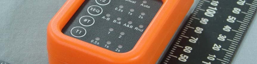
Click to zoom
Application Details
- Equipment Class
- DSC - Part 15 Security/Remote Control Transmitter
- Date of Grant
- Dec 01, 2010
- Application Purpose
- Original Equipment
- Date of Application
- Dec 01, 2010
- Equipment Note
- RF Transmitter
- Frequency Range
- 303.80000000 - 303.80000000
- Company
- Skytech II, Inc.
- Country
- United States
Documents & Files
Document Text
Text extracted from the exhibit documents filed with the FCC. Open a document above to read the original.
Users Manual
0 WIRELESS VOICE RELEASE SYSTEM Part Number: 45264 Instruction Manual WARNING: TO AVOID SERIOUS INJURY OR PROPERTY DAMAGE THOROUGHLY READ INSTRUCTIONS BEFORE USING. 1 Table of Contents Section Page I. Introduction / FCC Notice .................................................................... 1 II. Safety ................................................................................................. 2 III. Contents ............................................................................................. 3 IV. Features and Descriptions .................................................................. 4 V. Programming ......................................................................................................... 7 VI. Installation ........................................................................................... 8 VII. Operation..............................................................................10 VIII. Operational Examples.............................................................12 IX. Troubleshooting ................................................................................ 14 Warranty and Contact Information .............................................................................. 16 I. Introduction Congratulations on the purchase of your new Champion® Wireless Voice Release System. The Champion ® Wireless Voice Release System is an optional accessory for use with all Champion ® Easybird ® full automatic traps (Auto-Feed, 6 Packer & Doubles), SST and 180- Sporter traps. Features of the Champion® Wireless Voice Release system include: * Battery powered hand-held transmitter, high impact plastic case * Up to 100 yard transmission range * Single release system is upgradable to a double system by purchasing a 2nd Receiver * Adjustable to match cycle time of different trap machines * Quick and easy installation FCC NOTICE: This equipment has been tested and found to comply with the limits for a Class B digital device, pursuant to Part 15 of the FCC Rules. These limits are designed to provide reasonable protection against harmful interference in a residential installation. This equipment generates uses and can radiate radio frequency energy and, if not installed and used in accordance with the instructions, may cause harmful interference to radio communications. However, there is no guarantee that interference will not occur in a particular installation. If this equipment does cause harmful interference to radio or television reception, which can be determined by turning the equipment off and on, the user is encouraged to try to correct the interference by one or more of the following measures: Reorient or relocate the receiving antenna. Increase the separation between the equipment and receiver. Connect the equipment into an outlet on a circuit different from that to which the receiver is connected. Consult the dealer for help. This device complies with Part 15 of the FCC Rules. Operation is subject to the following two conditions: 1) This device may not cause harmful interference, and 2) This device must accept any interference received, including interference that may cause undesired operation. Making any changes or modifications not expressly approved by the manufacturer may void the user’s authority to operate this device. FCC ID: K9LSTTX1071 IC: 2439A-STTX1071 2 II. Safety WARNING: THOROUGHLY READ INSTRUCTIONS BEFORE INSTALLING OR OPERATING THE WIRELESS VOICE RELEASE SYSTEM! MAKE SURE TRAP IS SAFELY UNCOCKED BEFORE MOVING IN FRONT OF THE TRAP. ACCIDENTAL RELEASE OF THE TARGET AND/OR THROWING ARM CAN CAUSE SERIOUS INJURY OR DEATH! BEFORE INSTALLING THE WIRELESS VOICE RELEASE SYSTEM ON THE TRAP, MAKE SURE THAT THE THROWING ARM IS IN THE UNCOCKED POSITION, THE TRAP IS IN THE OFF POSITION AND THE TRAP IS DISCONNECTED FROM THE BATTERY. ALL PERSONNEL OPERATING THE TRAP SHOULD BE THOROUGHLY FAMILIAR WITH THE OPERATING INSTRUCTIONS AND THE SAFETY ISSUES RELATING TO THE TRAP. DO NOT LEAVE TRAP IN THE COCKED POSITION. ACCIDENTAL RELEASE OF THE THROWING ARM CAN OCCUR. DO NOT STAND IN FRONT OF THE TRAP WHEN IT IS IN THE COCKED POSITION. KEEP HANDS AND BODY AWAY FROM THE TRAP AND THROWING ARM PATH WHILE THE TRAP IS OPERATING. WHEN TRANSMITTER IS IN AUTO MODE AND ARMED, ANY LOUD NOISE MAY ACTIVATE RELEASE SEQUENCE AND LAUNCH A TARGET. DO NOT ARM TRANSMITTER UNTIL SHOOTER IS READY TO LAUNCH A TARGET. WARNING: FAILURE TO FOLLOW SAFETY RULES CAN RESULT IN SERIOUS INJURY OR DEATH! 3 III. Contents A – Receiver (Attach included antenna to top of receiver) B – Sound-Activated Transmitter C – Two AAA/1.5V Batteries for Transmitter D – Trap Connector E – Foot Pedal Connector F – Adhesive Velcro Mounting Pad G – Foam Microphone Wind Filter (Fits over microphone on transmitter if needed for windy conditions) A B D C E F G 4 IV. Features and Descriptions Receiver Unit A - ARM Button: o Press the ARM button to allow the receiver to accept transmitter commands and enable receiver output (arm). o Press the ARM button again to prevent the receiver from accepting transmitter commands and disable the receiver output (disarm). B - POWER LIGHT (Green): o Illuminates continuously when receiver is connected to 12V power. C - READY LIGHT (Red): o Illuminates continuously when receiver is armed. o Flashes when receiver is in “Learn” mode D - REMOVABLE ANTENNA: Must be attached for proper operation E - 12V POWER CONNECTIONS (Red and Black wires): o Red wire clip connects to positive (+) terminal on 12V battery o Black wire clip connects to negative (-) terminal on 12V battery F - OUTPUT CONNECTOR (White wires and connector): o Connects to foot pedal or hand release cable for trap Inside Controls (remove bottom panel): G - PROGRAMMING BUTTON: o Press button to enter LEARN mode. The LEARN mode will automatically cancel after 30 seconds if no transmission is received. H - ACTIVATION ADJUSTMENT DIAL: o Adjust for how long output relay will be activated (.5 to 3 sec) A B…
Text truncated - open the document above for the full version.
Cover Letter(s)
Date: Oct. 18 2010 Federal Communications Commission Office of Engineering and Technology Equipment Authorization Division 7345 Oakland Mills Road Columbia, Maryland 21046 Subject: Permanent Confidentiality request for FCC ID: K9LSTTX1071 To Whom It May Concern, Pursuant to sections 0.457 and 0.459 of CFR 47, the applicant requests permanent confidential treatment of the following information accompanying this application: Block Diagrams Schematics Operational Descriptions The above materials contain trade secrets and proprietary information not customarily released to the public. The public disclosure of these matters might be harmful to the applicant and provide unjustified benefits to its competitors. Sincerely, Christopher Flick / CEO _____________________________ (Signature)
External Photos
Report Number: MLT1007P15002 PHOTOGRAPHS OF EUT
ID Label/Location Info
Report Number: MLT1007P15002 Label Format: Label Position: Equipment Label 4.1cmX4.8cm This device complies with Part15 of the FCC Rules. Operation is subject to the following two conditions: (1) This device may not cause harmful interference, and (2) This device must accept any interference received , including Interference that may cause undesired operation. Trade Name : Skytech II Model No. : 45264, 60R186 FCC ID: K9LSTTX1071 Rear View
Internal Photos
Report Number: MLT1007P15002 Antenna (fixed frequency, non-adjustable)
Internal Photos
Report Number: MLT1007P15002 Report Number: MLT1007P15002
Test Report
Page: 1/ 27 Report Number: MLT1007P15002 (FCC : Part 15 Subpart C / ANSI C63.4-2003) Product : RF Transmitter Trade Name : Skytech II Model No. : 45264, 60R186 Applicant : Skytech II, Inc. Applicant Address : 9230 Conservation Way,Ft. Wayne, IN 46809, U.S.A. Page: 2/ 27 Report Number: MLT1007P15002 Report Number MLT1007P15002 Applicant Skytech II, Inc. Product RF Transmitter Sample Received Date 2010/07/09 Report Prepared By Jesse Tien Signature Date Prepared 2010/07/12 ~ 2010/07/27 Report Authorized By Roger Chen Signature Date Authorized 2010/10/11 Test By Max Light Technology Co., Ltd. Room 5, 8F, No.125, Section 3 Roosevelt Road, Taipei, Taiwan., R.O.C. Office : Tel: 886-2-2363-2447 Fax: 886-2-2363-2597 Lab. : Tel: 886-2-2663-3486 Fax: 886-2-2663-3582 I I t t m m a a y y b b e e d d u u p p l l i i c c a a t t e e d d c c o o m m p p l l e e t t e e l l y y f f o o r r l l e e g g a a l l u u s s e e w w i i t t h h t t h h e e a a l l l l o o w w a a n n c c e e o o f f t t h h e e a a p p p p l l i i c c a a n n t t . . I I t t s s h h a a l l l l n n o o t t b b e e r r e e p p r r o o d d u u c c e e d d e e x x c c e e p p t t i i n n f f u u l l l l , , w w i i t t h h o o u u t t t t h h e e w w r r i i t t t t e e n n a a p p p p r r o o v v a a l l o o f f o o u u r r l l a a b b o o r r a a t t o o r r y y . . Page: 3/ 27 Report Number: MLT1007P15002 Table of Contents : 1. General 5. 2. Conducted Emissions Requirements 7 3. Radiated Emissions Requirements 8. 4. Transmitter Bandwidth Measurements 18. 5. Transmitter Duty Cycle Measurements 20. 6. Verification of De-activation after 5 seconds 24. Appendix I ( EUT Test Setup ) 26. Appendix II ( Brand / Trade Name & Model No. Multiple Listee ) 27. Page: 4/ 27 Report Number: MLT1007P15002 CERTIFICATION We here by verify that : The test data, data evaluation, test procedures and equipment configurations shown in this report were made in accordance with the procedures given in ANSI C63.4-2003. All test were conducted by MLT(Max Light Technology Co.,Ltd) Room 5, 8F, No.125, Section 3 Roosevelt Road, Taipei, Taiwan, R.O.C Also, we attest to the accuracy of each. We further submit that the energy emitted by the sample EUT tested as described in the report is in compliance with radiated emission limit of FCC Rules Part 15 Subpart C Section 15.231. Applicant Name Skytech II, Inc. Applicant Address 9230 Conservation Way,Ft. Wayne,IN 46809,U.S.A. Manufacturer Name FEGO Precision Industrial Co., Ltd. Manufacturer Address 947 LIN SEN RD., WU-FENG SHIANG TAICHUNG HSIEN R.O.C. Equipment RF Transmitter Model No 45264, 60R186 FCC ID K9L STTX1071 Report Prepared By Jesse Tien Signature Report Authorized By Roger Chen Signature Page: 5/ 27 Report Number: MLT1007P15002 1. GENERAL 1.1 Introduction The following measurement report is submitted on behalf of Skytech II, Inc. In support of an Intentional Periodic Radiator certification in accordance with Part 2 Subpart J and Part 15 Subpart A And C of the Commission’s and Regulations. 1.2 Customer Details Applicant Name Skytech II, Inc. Applicant Address 9230 Conservation Way,Ft. Wayne,IN 46809,U.S.A. Manufacturer Name FEGO Precision Industrial Co., Ltd. Manufacturer Address 947 LIN SEN RD., WU-FENG SHIANG TAICHUNG HSIEN R.O.C. 1.3 Technical data of EUT Equipment RF Transmitter Model No 45264, 60R186 FCC ID K9L STTX1071 Power Type Powered by 3V Battery (AAA Size X2) The EUT (45264, 60R186) is remote transmitter. The operation frequency is 303.8Mhz. Press the button on remote transmitter, can set the Program RESET / ARM / T2 / SEQ / #T / T1 Continuous Pilot button. 1.4 Description of Support Equipment The EUT itself forms a system. No support equipment is required for its normal operation. Page: 6/ 27 Report Number: MLT1007P15002 1.5 Configuration of System Under Test 1.6 Test Procedure All measurements contained in this report were performed according to the techniques described in Measurement procedure ANSI C63.4: 2003 "Measurement of Intentional Radiators." 1.7 General Test Condition The conditions under which the EUT operates were varied to determine their effect on the equipment's emission characteristics. The final configuration of the test system and the mode of operation used during these tests was chosen as that which produced the highest emission levels. However, only those conditions which the EUT was considered likely to encounter in normal use were investigated. EUT Page: 7/ 27 Report Number: MLT1007P15002 2. Conducted Emissions Requirements The EUT operates solely by the battery. According to the rule of Section 15.207(c), the EUT exempt to the power line conducted test. Page: 8/ 27 Report Number: MLT1007P15002 3. Radiated Emissions Requirements 3.1 General Configuration: Prior to open-field testing, the EUT was placed in a shielded enclosure and scanned at a close distance to determine its emission characteristics. The physical arrangement of the EUT was varied (within the scope of arrangements likely to be encountered in actual use) to determine the effect on the unit's emanations in amplitude, directivity, and frequency. The exact system configuration which produced the highest emissions was noted so it could be reproduced later during the open-field tests. This was done to ensure that the final measurements would demonstrate the worst-case interference potential of the EUT. 3.2 General Configuration: Final radiation measurements were made on a three-meter, open-field test site. The EUT system was placed on a nonconductive turntable which is 0.8 meters height, top surface 1.0 x 1.5 meter. The spectrum was examined from 250 MHz to 2.5 GHz in order to cover the whole spectrum below 10th harmonic which could generate from the EUT. During the test, EUT was set to transmit continuously & Measurements spectrum range from 30 MHz to5 GHz is investigated. For measurements below 1 GHz the resolution bandwidth is set to 100 kHz for peak detection measurements or 120 kHz for quasi-peak detection me…
Text truncated - open the document above for the full version.
Test Setup Photos
Report Number: MLT1007P15002 Radiated Measurement Photos Front View of The Test Configuration Rear View of The Test Configuration
Contact Information
Applicant
Michael L. Rogers(Engineering Manager)
Technical Contact
QuieTekSabina Chen
[email protected]886 2 86013788
No. 5-22, Ruei-Shu Valley, Ruei-Ping Tsuen, · Taipei · Taiwan
Test Firm
Quietek Linkou EMC LabotortyJames Chang
Technical Specifications
| # | Rule Parts | Frequency Range | Power Output |
|---|---|---|---|
| 1 | 15.231 | 303.8 MHz - 303.8 MHz | - |
Other Applications from Skytech II, Inc.
K9LAFTS3TX
Jul 17, 2022Remote control transmitter
Equipment Class
DSC - Part 15 Security/Remote Control TransmitterK9L8001TX
Jun 05, 2021Remote Control Transmitter
Equipment Class
DSC - Part 15 Security/Remote Control Transmitter
K9L-4001THATX
Apr 22, 2020Wireless Remote Controller (TX)
Equipment Class
DSC - Part 15 Security/Remote Control TransmitterK9L3001-1TX
Feb 18, 2020Remote Control
Equipment Class
DSC - Part 15 Security/Remote Control Transmitter
K9LREMOTION
Jul 16, 2013Transmiter
Equipment Class
DTS - Digital Transmission System