K9LTS-R-1Digital Thermostat Transmitter
Skytech II, Inc.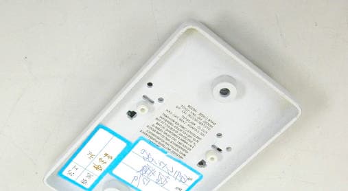
Click to zoom
Application Details
- Equipment Class
- DSC - Part 15 Security/Remote Control Transmitter
- Date of Grant
- Jan 12, 2003
- Application Purpose
- Original Equipment
- Date of Application
- Jan 12, 2003
- Equipment Note
- Digital Thermostat Transmitter
- Frequency Range
- 303.87500000 - 303.87500000
- Company
- Skytech II, Inc.
- Country
- United States
Documents & Files
Document Text
Text extracted from the exhibit documents filed with the FCC. Open a document above to read the original.
Users Manual
SKYTECH II, INC 9230 Conservation Way, Fort Wayne,FCC ID: K9LTS-R-1 In 46809, USA Tel: 260-459-1703 Fax: 260-459-1592 SKY TS/R-1 Digital Thermostat USER MANUAL 1) Rear Case- press ON/OFF(ON-the back left button, OFF- the back right button) at the same time to change C or F 2) Front Case- move rod to OFF then send 3 times OFF signal to receiver 3) Front Case- move rod to ON then send 3 times ON signal to receiver 4) Front Case- move rod between OFF & ON for adjusting desire temperature. When temperature below adjusted temperature then it will turn on receiver with flame icon after 2 minutes. When temperature higher than adjusted temperature then it will disable the flame icon then turn off the receiver. It will have SET icon when rod was moved between ON & OFF scale. The action of SKY TS/R-1 Use component RT-103AT to sense the temperature and compare with ROD SETTING temperature which setting by users. When setting temperature below the room temperature then transmitter will send 3 times signals to turn on the receivers. If SETTING temperature is higher than room temperature then transmitter will send 3 times signals to turn off the receiver (fire place). Caution: The changes or modifications not expressly approved by the party responsible for compliance could void the user’s authority to operate the equipment. “Operation is subject to the following two conditions: (1) this device may not cause interference, and (2) this device must accept any interference, including interference that may cause undesired operation of the device.”
Cover Letter(s)
From: [email protected] Sent: Wednesday, January 08, 2003 6:15 AM To: Mike Kuo Subject: Re: SKYTECH II, INC., FCC ID:K9LTS-R-1, AN02T2470 Hi Mike, The answer of question #1: The client changed the location of FCC ID label to the rear of the case. User will find the label easily. Attached please find the photo of FCC ID label. <<ID Label Location.pdf>> The answer of question #2: Please sees the same photo. <<ID Label Location.pdf>> There are two small button on the rear case. The answer of question #3: Attached please find the new user manual. <<User manual.pdf>> The client explained that the product just sent three times ON/OFF signal to receiver. So it comply with 15.231 periodical transmission requirement. Best regards, Joe Hsieh ETC, Taiwan ----- Original Message ----- From: "Mike Kuo" <[email protected]> To: <[email protected]> Sent: Wednesday, December 25, 2002 9:20 AM Subject: FW: SKYTECH II, INC., FCC ID:K9LTS-R-1, AN02T2470 > > > -----Original Message----- > From: CERTADM > Sent: Tuesday, December 24, 2002 5:19 PM > To: '[email protected]' > Subject: SKYTECH II, INC., FCC ID:K9LTS-R-1, AN02T2470 > > > Notice_content > ------------- > Question #1: The proposed FCC ID label location does not comply with section > 2.925(d)(2) of FCC rules. The proposed label location is located on the > mounting plate which not necessary will be related to the EUT. In addition, > once installed, the FCC ID label will not be visible. Please considering > 2.925(d)(2) requirements and provided revised FCC ID label format and > location. > > Question #2: Page 1 of user manual indicates that there is on/off button on > the rear case. Such on/off button can not be located on the external or > internal photos. Please explain and point out such button on the photos. > > Question #3: Page 1 of user manual indicates that front case, move rod to ON > sent continuous ON signal to receiver. It sounds like this device is > transmitting continuously which does not comply with 15.231 periodical > transmission requirement. Please explain. > > Best Regards > > Mike Kuo / TCB Certifier. > The items indicated above must be submitted before processing can continue > on the above referenced application. Failure to provide the requested > information within 60 days of the original e-mail date may result in > application dismissal and forfeiture of the filing fee. Also, please note > that partial responses increase processing time and should not be submitted. > Any questions about the content of this correspondence should be directed to > the e-mail address listed below the name of the sender.
External Photos
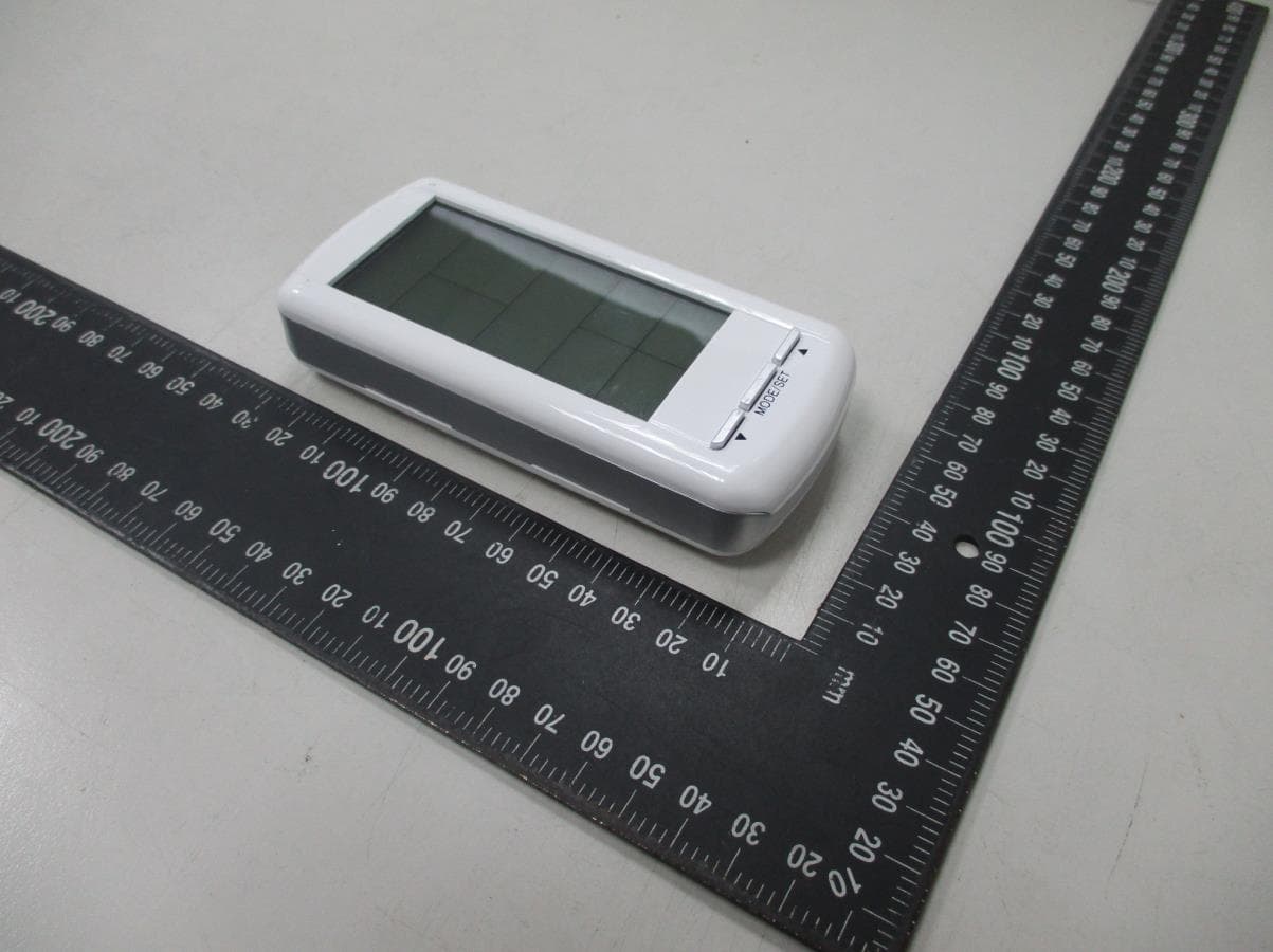
ETC Report No.: ET91S-12-050Page A1 of A1 FCC ID: K9LTS-R-1 ANNEX A: EXTERNAL CONSTRUCTION PHOTOS OF EUT 1. Front view of EUT 2. Rear view of EUT
Internal Photos
ETC Report No.: ET91S-12-050Page B1 of B3 FCC ID: K9LTS-R-1 ANNEX B: INTERNAL CONSTRUCTION PHOTOS OF EUT 1. Label 1 2. Inside 1 of EUT ETC Report No.: ET91S-12-050Page B2 of B3 FCC ID: K9LTS-R-1 3. Inside 2 of EUT 4. Inside 3 of EUT ETC Report No.: ET91S-12-050Page B3 of B3 FCC ID: K9LTS-R-1 5. Front view of PCB 6. Front view of PCB
Test Report
FCC ID.: K9LTS-R-1 Rev. No 1.0 FCC Part 15 Subpart C EMI TEST REPORT of E.U.T. : Digital Thermostat Transmitter FCC ID. : K9LTS-R-1 MODEL : SKY TS/R-1 Working Frequency : 303.875 MHz for APPLICANT: SKYTECH II, INC ADDRESS: 9230 Conservation Way, Fort Wayne, In 46809,USA Test Performed by ELECTRONICS TESTING CENTER, TAIWAN NO. 8, LANE 29, WEN-MING RD., LO-SHAN TSUN, KUI-SHAN HSIANG, TAOYUAN HSIEN 333, TAIWAN, R.O.C. Tel: (03) 3276170-3276174 Fax: (03) 3276188 Report Number: ET91S-12-050 ETC Report No.:ET91S-12-050FCC ID.: K9LTS-R-1 Rev. No 1.0 TEST REPORT CERTIFICATION Applicant: SKYTECH II, INC 9230 Conservation Way, Fort Wayne, In 46809,USA Manufacturer: Win Home Electronic Factory Shenzhen, Lung Kang District, Heng Kang Area, Hur Ou Chun, Chin Yen Industrial 2, Shenzhen, China Description of EUT: a) Type of EUT: Digital Thermostat Transmitter b) Model No.: SKY TS/R-1 c) Serial No.: 200212 d) FCC ID: K9LTS-R-1 e) Working Frequency: 303.875 MHz f) Power Supply: DC 3V Battery x 2 (Type: CR2032) Regulation Applied: FCC Rules and Regulations Part 15 Subpart C (2002) I HEREBY CERTIFY THAT; The data shown in this report were made in accordance with the procedures given in ANSI C63.4 and the energy emitted by the device was founded to be within the limits applicable. I assume full responsibility for accuracy and completeness of these data. Note:1.The results of the testing report relate only to the items tested. 2.The testing report shall not be reproduced except in full, without the written approval of ETC. 3.The report must not be used by the client to claim product endorsement by NVLAP or any agency of the U.S. Government. Issue Date : Dec. 13, 2002 Test Engineer : Approve & Authorized Signer : Win-Po Tsai, Manager, NVLAP Signatory EMC Dept. of ELECTRONICS TESTING CENTER, TAIWAN ETC Report No.:ET91S-12-050FCC ID.: K9LTS-R-1 Rev. No 1.0 Table of Contents Page 1. GENERAL INFORMATION............................................................................................................................................................1 1.1 PRODUCT DESCRIPTION..................................................................................................................................................................1 1.2 CHARACTERISTICS OF DEVICE:.......................................................................................................................................................1 1.3 TEST METHODOLOGY......................................................................................................................................................................1 1.4 TEST FACILITY..................................................................................................................................................................................1 2. DEFINITION AND LIMITS..............................................................................................................................................................2 2.1 DEFINITION........................................................................................................................................................................................2 2.2 RESTRICTED BANDS OF OPERATION.............................................................................................................................................2 2.3 LIMITATION.......................................................................................................................................................................................3 2.4 LABELING REQUIREMENT...............................................................................................................................................................4 2.5 USER INFORMATION.........................................................................................................................................................................4 3. RADIATED EMISSION MEASUREMENT....................................................................................................................................5 3.1 APPLICABLE STANDARD.................................................................................................................................................................5 3.2 MEASUREMENT PROCEDURE..........................................................................................................................................................5 3.3 TEST DATA.........................................................................................................................................................................................7 3.4 FIELD STRENGTH CALCULATION..................................................................................................................................................8 3.5 RADIATED TEST EQUIPMENT.........................................................................................................................................................8 3.6 MEASURING INSTRUMENT SETUP.................................................................................................................................................8 3.7 RADIATED MEASUREMENT PHOTOS.............................................................................................................................................9 4. BANDWIDTH OF EMISSION AND DUTY FACTOR..............................................................................................................14 4.1 APPLICABLE STANDARD PLOT GRAPHIC OF BANDWIDTH AND DUTY FACTOR...............................................................14 4.2 TEST EQUIPMENT...........................................................................................................................................................................14 4.3 ACTIVE TIME...........................................................................................................…
Text truncated - open the document above for the full version.
Test Setup Photos
ETC Report No.:ET91S-12-050Sheet 1 of 1 Sheets FCC ID.: SKY TS/R-1 Radiated Measurement Photos
Contact Information
Applicant
Michael L. Rogers(Engineering Manager)
Test Firm
Electronics Testing Center, TaiwanWinpo Tsai
Technical Specifications
| # | Rule Parts | Frequency Range | Power Output |
|---|---|---|---|
| 1 | 15.231 | 303.875 MHz - 303.875 MHz | - |
Other Applications from Skytech II, Inc.
K9LAFTS3TX
Jul 17, 2022Remote control transmitter
Equipment Class
DSC - Part 15 Security/Remote Control TransmitterK9L8001TX
Jun 05, 2021Remote Control Transmitter
Equipment Class
DSC - Part 15 Security/Remote Control Transmitter
K9L-4001THATX
Apr 22, 2020Wireless Remote Controller (TX)
Equipment Class
DSC - Part 15 Security/Remote Control TransmitterK9L3001-1TX
Feb 18, 2020Remote Control
Equipment Class
DSC - Part 15 Security/Remote Control Transmitter
K9LREMOTION
Jul 16, 2013Transmiter
Equipment Class
DTS - Digital Transmission System