K9LTS-R-2AFireplace Remote Control
Skytech II, Inc.
Click to zoom
Application Details
- Equipment Class
- DSC - Part 15 Security/Remote Control Transmitter
- Date of Grant
- Sep 26, 2004
- Application Purpose
- Original Equipment
- Date of Application
- Sep 26, 2004
- Equipment Note
- Fireplace Remote Control
- Frequency Range
- 303.87000000 - 303.87000000
- Company
- Skytech II, Inc.
- Country
- United States
Documents & Files
Document Text
Text extracted from the exhibit documents filed with the FCC. Open a document above to read the original.
Users Manual
REV 3/3/04 Page 1 of 5 TS/R-2 INSTALLATION AND OPERATING INSTRUCTIONS INTRODUCTION SKYTECH’S remote wall mount thermostat system was developed to provide a safe, reliable and user-friendly wireless remote wall mount thermostat for gas heating appliances. Battery operation allows the system to operate independently of household current. The system operates on radio frequencies with non-directional signals. The SYSTEMS operating range is approximately 20 feet. The system operates on one of 255 security codes programmed at the factory. COMPONENTS THE SKYTECH TS/R-2 MUST BE INSTALLED EXACTLY AS OUTLINED IN THESE INSTRUCTIONS. READ COMPLETELY BEFORE ATTEMPTING INSTALLATION. FOLLOW INSTRUCTIONS CAREFULLY DURING INSTALLATION. ANY MODIFICATION OF THE SKYTECH TS/R-2 OR ANY OF ITS COMPONENTS WILL VOID THE WARRANTY AND MAY POSE A FIRE HAZARD. WALL MOUNT THERMOSTAT The wall/transmitter operates on (2) 3V Button Cell (Included) which powers the LCD screen. These batteries are made specifically for remote controls and electronic lighters. Before using the transmitter the 3V batteries must be installed into the battery compartments. It is recommended that ALKALINE batteries always be used for longer battery life and maximum operational performance. Upon initial use, there may be a delay of five seconds before the remote receiver will respond to the transmitter. This is part of the system’s design. If the LCD screen will not come on, check the 3V Button Cell battery. To activate LCD screen install the (2) 3V button cell batteries. The wall thermostat operates on a (2) 3V button cell batteries (included) made specifically for remote controls. Before using the wall thermostat, install the two (2) 3V button cell batteries. Follow instructions below. First you must remove the face of the thermostat. This is Done by sliding the face up about 1/2” then pull the face off the base plate. As shown at the right. TO INSTALL BATTERIES IN THE WIRELESS THERMOSTAT 1. Remove face from backing plate and locate the (2) holders for the 3V button cell batteries. 2. Slide the button cell batteries into the battery holders. (Make sure that the batteries are installed with the (+) plus side facing you). TO REMOVE THE BATTERIES IN THE WIRELESS THERMOSTAT 1. Remove face from backing plate and locate the (2) holders for the 3V button cell batteries. 2. Insert a small screwdriver into the slot above the button cell battery and push the battery out (Slots shown in picture to the left). ROOM TEMP ON OFF SET ROOM TEMP THERMO MODE “SET” ON SET OFF LCD DISPLAY ON/UP BUTTON OFF/DOWN BUTTON SET BUTTON TOP TRANSMITTER REMOTE RECEIVER SLIDE BUTTONS REMOTE ON OFF SLIDE-ON COVERPLATE R E M O T E ON OFF 2 ea. 12V (A23) Transmitter battery(included in transmitter) 4 ea. WALL-MOUNT COVERPLATE HARDWARE (2) 3V Button Cell Transmitter batteries (included in transmitter) AA BATTERIES 3V 3V ROOM TEMP ON SET OFF SET WIRING KIT BACK OF UNIT (2) 3 Volt Button Cell Batteries Battery Removal Slots + Plus Side + Plus Side REV 3/3/04 Page 2 of 5 TOP Requires 4-AA 1.5V alkaline batteries (not included) Battery cover slides on/off Slide Switch ON REMOTE OFF WALL Plastic Switch Box Remote Receiver Cover Plate Receiver Slide Button TOP R E M O T E ON OFF WALL MOUNTING THE THERMOSTAT 1. The wireless Thermostat must be located within 20’ of the receiver, This is proper operational distance. 2. Remove face from backing plate as shown at the start of these instructions then locate the (2) two holes that mount the plate to the wall. 3. Locate the (2) two mounting holes and mark the holes on the wall. 4. Use the (2) two dry wall anchors and screws ( that are supplied) to mount the base plate to the wall as shown. 5. Thermostat can also be mounted onto an existing (Plastic) electrical box. 6. Base plate should be mounted level on the wall for best operation. REMOTE RECEIVER IMPORTANT: THE REMOTE RECEIVER SHOULD BE POSITIONED WHERE AMBIENT TEMPERATURES DO NOT EXCEED 130 DEGREE F. The remote receiver (right) operates on four 1.5V AA- size batteries (Included). It is recommended that ALKALINE batteries be used for longer battery life and maximum microprocessor performance. IMPORTANT: New or fully charged batteries are essential to proper operation of the remote receiver. NOTE: The remote receiver will only respond to the transmitter when the 3-position slide button on the remote receiver is in the REMOTE (center) position. The remote receiver houses the microprocessor that responds to commands from the thermostat to control system operation. The remote receiver has a 3-position slide switch (see figure at right) for selecting the mode of operation: ON/REMOTE/OFF. • With the slide switch in the ON position (toward the word TOP), the system will remain on until the slide switch is placed in the OFF or REMOTE position. This manual switch will turn ON or OFF the system, without the transmitter or good batteries. • With the slide switch in the REMOTE position (centered), the system will only operate if the remote receiver receives commands from the thermostat. Upon initial use or after an extended period of no use the ON button must be pressed for up to five seconds. • With the slide switch in the OFF position (away from the word TOP), the system is off. • It is suggested that the slide switch be placed in the OFF position if you will be away from your home for an extended period of time. If the remote receiver is mounted out of children’s reach, placing the slide switch in the OFF position also functions as a safety “lock out” by both turning the system off and rendering the thermostat inoperative. INSTALLATION NOTE: When the remote receiver is installed as a wall switch, It is recommended that it be installed in a PLASTIC switch box. Remote functions may not operate properly if the remote receiver is installed in a steel switch box. Make sure the remote receiver switch is in the OFF position (toward the small hole on the receiver’s face). It is recommended that 18 gauge, …
Text truncated - open the document above for the full version.
Block Diagram
1 2 3 4 56 A BC D 6 5 4 3 2 1 D CB A Title Number Revision Size B Date: 30-Aug-2004 Sheet of File: F:\Protel\AAT105(TS-R-2)\BLOCK\BLOCK.ddb Drawn By: LCD Display LCD Driver RF Output Temperature Key Input MCU.
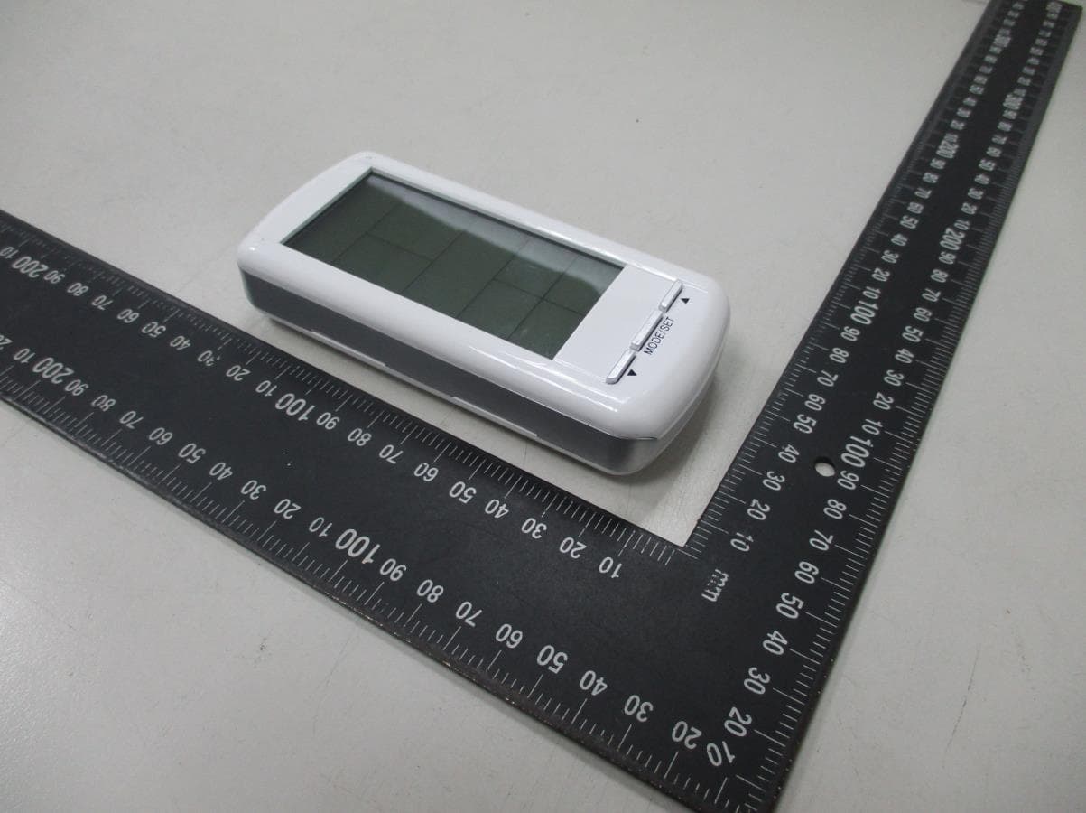
External Photos
MAX LIGHT Report Number: MLT0408P15001 FCC ID: K9LTS-R-2A Technology Lab MAX LIGHT Report Number: MLT0408P15001 FCC ID: K9LTS-R-2A Technology Lab
ID Label/Location Info
MAX LIGHT Report Number: MLT0408P15001 FCC ID: K9LTS-R-2A Technology Lab Label Format: This device complies with Part15 of the FCC Rules. Operation is subject to the following two conditions: (1) This device may not cause harmful interference,and (2) This device must accept any interference received ,including. Interference that may cause undesired operation. Model : TS/R-2A FCC ID : K9LTS-R-2A Label Position: Equipment Lable 3.5CMX2.5CM Rear View
Internal Photos
MAX LIGHT Report Number: MLT0408P15001 FCC ID: K9LTS-R-2A Technology Lab MAX LIGHT Report Number: MLT0408P15001 FCC ID: K9LTS-R-2A Technology Lab MAX LIGHT Report Number: MLT0408P15001 FCC ID: K9LTS-R-2A Technology Lab
Schematics
ABCD DCBA Title Number Revision Size B Date: 31-Aug-2004 Sheet of File: F:\Euroglory\FCC\AAT105v11\AAT105v11.DDB Drawn By: R251K R1503T C1103 AAT105 R3 100k R751R C42P C21P C3 8P C5 103 L1 1UH ANT1 VC13P C72P Q1C3838 REF SNR R41M CRG CS 1 CLK 2 DI 3 DO 4 VSS 5 VCC 8 U293LC46 RF Circuit N4 N5 N6 BAT-LOW RF 123456789 101112 LCD1GS-33040-TRZC COM0COM1COM2COM3 S0S1S2S3S4 P50 1 P67 2 P66 3 VDD 4 P65 5 P64 6 P63 7 P62 8 P61 9 P60 10 VSS 11 P53 12 P52 13 P51 14 U3EM78P153S 6V 6V VCCVCC VCC VCC KO C8104 C6104 R8 100R DATA WRECS CRG SNRREFRFCSECSWR DATABAT-LOWIRQ WRDATA KO S5 CC2 1 VO15N 2 VEE 3 COM0 4 COM1 5 COM2 6 COM3 7 SEG0 8 SEG1 9 SEG2 10 SEG3 11 SEG4 12 SEG5 13 SEG6 14 SEG7 15 SEG8 16 SEG9 17 SEG10 18 SEG11 19 SEG12 20 SEG13 21 SEG14 22 SEG15 23 SEG16 24 SEG17 25 SEG18 26 SEG19 27 SEG20 28 SEG21 29 SEG22 30 SEG23 31 SEG24 32 SEG25 33 SEG26 34 SEG27 35 SEG28 36 SEG29 37 SEG30 38 SEG31 39 CS 40 RD 41 WR 42 DATA 43 VSS 44 OSC0 45 OSC1 46 VDD 47 IRQ 48 BZ 49 BZ 50 CC1 51 U5HT1620 C9104 R9100K IRQ VCC VCC U4 32.768KHz DATAWRCS C10104 VCC R103M C11104 VCC S0S1S2S3S4S5 1 1 2 2 PAD1B.3V PAD 1 1 2 2 PAD2B.3V PAD 6V VCC SW1 Down SW2 Up SW3 Mode R61KR51K 1 1 2 2 3 3 U1HT7050A S6S7 S6S7 COM0 COM1 COM2 COM3 R1110K VCC
Test Report
Product : Fireplace Remote Control Applicant : SKYTECH II, INC. FCC ID : K9LTS-R-2A Model : TS/R-2A Report No. : MLT0408P15001 Test Date : 09/02/2004 Test By Max Light Technology Co.,Ltd. Room 5, 8F, No.125, Section 3 Roosevelt Road, Taipei, Taiwan., R.O.C. Tel: 886-2-363-2447 Fax: 886-2-363-2597 T T h h e e t t e e s s t t r r e e p p o o r r t t c c o o n n s s i i s s t t s s o o f f 2 2 9 9 p p a a g g e e s s i i n n t t o o t t a a l l . . I I t t m m a a y y b b e e d d u u p p l l i i c c a a t t e e d d c c o o m m p p l l e e t t e e l l y y f f o o r r l l e e g g a a l l u u s s e e w w i i t t h h t t h h e e a a l l l l o o w w a a n n c c e e o o f f t t h h e e a a p p p p l l i i c c a a n n t t . . I I t t s s h h a a l l l l n n o o t t b b e e r r e e p p r r o o d d u u c c e e d d e e x x c c e e p p t t i i n n f f u u l l l l , , w w i i t t h h o o u u t t t t h h e e w w r r i i t t t t e e n n a a p p p p r r o o v v a a l l o o f f o o u u r r l l a a b b o o r r a a t t o o r r y y . . MAX LIGHT MEASUREMENT REPORT Page: 2/29 Report Number: MLT0408P15001 FCC ID: K9LTS-R-2A Technology Lab Table of Contents : MAX LIGHT MEASUREMENT REPORT Page: 3/29 Report Number: MLT0408P15001 FCC ID: K9LTS-R-2A Technology Lab CERTIFICATION We here by verify that : The test data, data evaluation, test procedures and equipment configurations shown in this report were made in accordance with the procedures given in ANSI C63.4:2001. All test were conducted by MLT (Max Light Technology Co.,Ltd) Room 5, 8F, No.125, Section 3 Roosevelt Road, Taipei, Taiwan, R.O.C Also, we attest to the accuracy of each. We further submit that the energy emitted by the sample EUT tested as described in the report is in compliance with radiated emission limit of FCC Rules Part 15 Subpart C Section 15.231. EUT : Fireplace Remote Control Applicant : SKYTECH II, INC. 9230 CONSERVATION WAY, FORT WAYNE, IN 46809, U.S.A Manufacturer : FEGO PRECISION INDUSTRIAL CO., LTD. NO. 947 LIN-SEN RD., WU FONG SHIANG, TAICHUNG HSIEN, TAIWAN Model No : TS/R-2A FCC ID : K9LTS-R-2A Prepared by : Approved by : Country Huang Roger Chen MAX LIGHT MEASUREMENT REPORT Page: 4/29 Report Number: MLT0408P15001 FCC ID: K9LTS-R-2A Technology Lab 1.1 Introduction The following measurement report is submitted on behalf of SKYTECH II, INC.In support of an Intentional Periodic Radiator certification in accordance with Part 2 Subpart J and Part 15 Subpart A And C of the Commission’s and Regulations. 1.2 Description of EUT EUT : Fireplace Remote Control Applicant : SKYTECH II, INC. 9230 CONSERVATION WAY, FORT WAYNE, IN 46809, U.S.A Manufacturer : FEGO PRECISION INDUSTRIAL CO., LTD. NO. 947 LIN-SEN RD., WU FONG SHIANG, TAICHUNG HSIEN, TAIWAN Model No : TS/R-2A FCC ID : K9LTS-R-2A Power Type : Powered by DC 6V Button Cell battery. The EUT(TS/R-2A) is remote wall mount thermostat system. The operation frequency is 303.87Mhz. Press the button on remote transmitter, can set the can set the ON/OFF/SET button. MAX LIGHT MEASUREMENT REPORT Page: 5/29 Report Number: MLT0408P15001 FCC ID: K9LTS-R-2A Technology Lab 1.3 Description of Support Equipment The EUT itself forms a system. No support equipment is required for its normal operation. 1.4 Configuration of System Under Test EUT 1.7 Test Procedure All measurements contained in this report were performed according to the techniques described in Measurement procedure ANSI ANSI C63.4:2001 "Measurement of Intentional Radiators." 1.8 General Test Condition The conditions under which the EUT operates were varied to determine their effect on the equipment's emission characteristics. The final configuration of the test system and the mode of operation used during these tests was chosen as that which produced the highest emission levels. However, only those conditions which the EUT was considered likely to encounter in normal use were investigated. MAX LIGHT MEASUREMENT REPORT Page: 6/29 Report Number: MLT0408P15001 FCC ID: K9LTS-R-2A Technology Lab The EUT operates solely by the battery. According to the rule of Section 15.207(c), the EUT exempt to the power line conducted test. MAX LIGHT MEASUREMENT REPORT Page: 7/29 Report Number: MLT0408P15001 FCC ID: K9LTS-R-2A Technology Lab 3.1 General Configuration: Prior to open-field testing, the EUT was placed in a shielded enclosure and scanned at a close distance to determine its emission characteristics. The physical arrangement of the EUT was varied (within the scope of arrangements likely to be encountered in actual use) to determine the effect on the unit's emanations in amplitude, directivity, and frequency. The exact system configuration which produced the highest emissions was noted so it could be reproduced later during the open-field tests. This was done to ensure that the final measurements would demonstrate the worst-case interference potential of the EUT. 3.2 General Configuration: Final radiation measurements were made on a three-meter, open-field test site. The EUT system was placed on a nonconductive turntable which is 0.8 meters height, top surface 1.0 x 1.5 meter. The spectrum was examined from 250 MHz to 2.5 GHz in order to cover the whole spectrum below 10th harmonic which could generate from the EUT. During the test, EUT was set to transmit continuously & Measurements spectrum range from 30 MHz to5 GHz is investigated. For measurements below 1 GHz the resolution bandwidth is set to 100 kHz for peak detection measurements or 120 kHz for quasi-peak detection measurements. Peak detection is used unless otherwise noted as quasi-peak. For measurements above 1 GHz the resolution bandwidth is set to 1 MHz, then the video bandwidth is set to 1 MHz for peak measurements and 10 Hz for average measurements. MAX LIGHT MEASUREMENT REPORT Page: 8/29 Report Number: MLT0408P15001 FCC ID: K9LTS-R-2A Technology Lab A nonconductive material surrounded the EUT to supporting the EUT for standing on tree orthogonal planes. At each condition, the EUT was rotated 3…
Text truncated - open the document above for the full version.
Test Setup Photos
MAX LIGHT MEASUREMENT REPORT Report Number: MLT0408P15001 FCC ID: K9LTS-R-2A Technology Lab Test Configuration: Front View of The Test Configuration MAX LIGHT MEASUREMENT REPORT Report Number: MLT0408P15001 FCC ID: K9LTS-R-2A Technology Lab Rear View of The Test Configuration
Contact Information
Applicant
Michael L. Rogers(Engineering Manager)
Test Firm
Max Light Technology Co., Ltd.Jesse Tien
Technical Specifications
| # | Rule Parts | Frequency Range | Power Output |
|---|---|---|---|
| 1 | 15.231 | 303.87 MHz - 303.87 MHz | - |
Other Applications from Skytech II, Inc.
K9LAFTS3TX
Jul 17, 2022Remote control transmitter
Equipment Class
DSC - Part 15 Security/Remote Control TransmitterK9L8001TX
Jun 05, 2021Remote Control Transmitter
Equipment Class
DSC - Part 15 Security/Remote Control Transmitter
K9L-4001THATX
Apr 22, 2020Wireless Remote Controller (TX)
Equipment Class
DSC - Part 15 Security/Remote Control TransmitterK9L3001-1TX
Feb 18, 2020Remote Control
Equipment Class
DSC - Part 15 Security/Remote Control Transmitter
K9LREMOTION
Jul 16, 2013Transmiter
Equipment Class
DTS - Digital Transmission System