L7KTSPA-01Ultrasite EDGE Base Transceiver Station
Nokia Solutions and Networks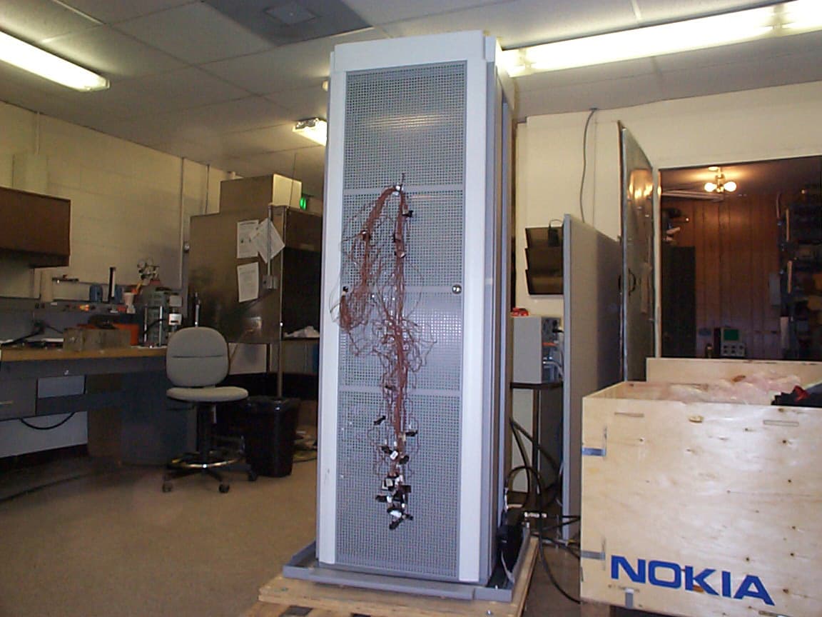
Click to zoom
Application Details
- Equipment Class
- PCB - PCS Licensed Transmitter
- Date of Grant
- Sep 17, 2000
- Application Purpose
- Original Equipment
- Date of Application
- Sep 17, 2000
- Equipment Note
- Ultrasite EDGE Base Transceiver Station
- Frequency Range
- 1930.20000000 - 1989.80000000
- Company
- Nokia Solutions and Networks
- Country
- United States
Documents & Files
Document Text
Text extracted from the exhibit documents filed with the FCC. Open a document above to read the original.
ID Label/Location Info
FCC Part 24 Sample Label Exhibit and Location (TSPA) Background color is white Text color is black Complies with Part 24, FCC rules. FCC ID : L7KTSPA-01 200% of Actual Size
Test Report
FCC ID: L7KTSPA-01 September 6, 2000 (revised November 14, 2001) Federal Communications Commission Authorization and Evaluation Division 7435 Oakland Mills Road Columbia, MD 21046 Attention:Applications Examiner Applicant:Nokia Networks 6000 Connection Drive Irving, TX 75039 Equipment: UltraSite EDGE Base Transceiver Station FCC ID: L7KTSPA-01 Specification:for a 47 CFR 24 Licensed Certification Dear Examiner: The following application for Grant of Equipment Authorization is presented on behalf of Nokia Telecommunications, Inc. for the Licensed Certification of their Model: UltraSite EDGE BTS Enclosed, please find a complete data and documentation package demonstrating that this device complies with the technical requirements of 47 CFR 24. If you have any questions, please contact the undersigned, who is authorized to act as Agent. Sincerely, Chris Harvey, Director EMC Laboratory MET Laboratories, Inc. FCC ID: L7KTSPA-01 EMC1349A- 2 -August 30, 2000 MET Laboratories, Inc. Safety Certification - EMI - Telecom Environmental Simulation 914 WEST PATAPSCO AVENUE ! BALTIMORE, MARYLAND 21230-3432 ! PHONE (410) 354-3300 ! FAX (410) 354-3313 ENGINEERING TEST REPORT in support of the Application for Grant of Equipment Authorization EQUIPMENT: Ultrasite EDGE Base Transceiver Station FCC ID:L7KTSPA-01 Specification:47 CFR 24 On Behalf of the Applicant:Nokia Networks. 6000 Connection Drive Irving, TX 75039 Manufacturer:Nokia Networks. 6000 Connection Drive Irving, TX 75039 Manufacturer’s RepresentativeMr..Steve Mitchell Test Date(s):July 31 thru August 7, 2000 ENGINEERING STATEMENT I ATTEST: the measurements shown in this report were made in accordance with the procedures indicated, and that the emissions from this equipment were found to be within the limits applicable. I assume full responsibility for the accuracy and completeness of these measurements. On the basis of the measurements made, the equipment tested is capable of operation in accordance with the requirements of Part 24 of the FCC Rules under normal use and maintenance. _____________________________ Liming Xu EMC Engineer, MET Laboratories FCC ID: L7KTSPA-01 EMC1349A- 3 -August 30, 2000 1.0INTRODUCTION The following data is presented on behalf of the Applicant, Nokia Networks, as verification of the compliance of the Nokia PCS(BTS), Ultrasite EDGE to the requirements of 47 CFR 24. 2.0TEST SITE All testing was conducted at MET Laboratories, Inc., 914 West Patapsco Avenue, Baltimore, Maryland 21230- 3493. Radiated emissions measurements were performed on a three-meter open area test site (OATS). A complete site description is on file with the FCC Laboratory Division as 31040/SIT/MET. 3.0TEST EQUIPMENT USED ManufacturerEquipmentCalibration Due Date @ time of testing Cal. Interval Hewlett Packard8563A Spectrum Analyzer6/14/01annual EMCOBiconical Antenna 31044/10/01annual EMCOEMCO Log Periodic Antenna4/10/01annual EMCODouble Ridge Guided Horn2/17/01annual Hewlett Packard8594EM Analyzer11/20/00annual Hewlett Packard8591E Analyzer8/12/00annual SolarLISN8/27/00annual 4.0EQUIPMENT UNDER TEST CONFIGURATION The Base Transceiver Station (BTS) was configured with AC power supply modules and an external PC to program the EUT to output a PCS (i.e.GMSK Modulation type) RF signal. The EUT with host external computer was configured for maximum signal gain and bandwidth. The EUT was operated in a manner representative of the typical usage of the equipment. During all testing, system components were manipulated within the confines of typical usage to maximize each emission. 5.0TEST TYPE(S) 5.1Radiated Emissions: 47 CFR2.1053, , 24.238(a) 5.2Occupied Bandwidth: 47 CFR2.1049 5.3RF Power Output: 47 CFR 2.1046, 24.232(a), (c) 5.4Spurious Emission at Antenna Terminals: 47 CFR 2.1051, 24.238(a) 5.5Spurious Emission at Antenna Terminals at Frequency Block edges +/- 1 MHz, 47 CFR 2.1051, 24.238(b) 5.6Frequency Stability over temperature variations: 47 CFR 2.1055(a)(1) 5.7Frequency Stability over variations in supply voltage: 47 CFR 2.1055(d)(1) 5.8AC Line Conducted Emissions: 47 CFR 15.107 5.9 Modulation Characteristics: 47 CFR 2.1047(a) FCC ID: L7KTSPA-01 EMC1349A- 4 -August 30, 2000 E(V/m) 1m ' 49.2X32.5 1 E(V/m) 1m '39.987V/mor152.1dbμV/m@1m 43%10Log(32.5)'58.11dB 152.1dBμV/m&58.11dB'93.99dBμV/m@1m E(V/m) 3m ' 49.2X32.5 3 E(V/m) 3m '13.33V/mor133142.1dbμV 142.1&58.11'83.99dBμV/m@3m 6.0TEST RESULTS 6.1TEST TYPE: Radiated Emissions 6.1.1TECHNICAL SPECIFICATION:2.1053; 24.238(a) 6.1.2TEST DATE(S):8/7/00 6.1.3MEASUREMENT PROCEDURES: As required by §2.1053, field strength of spurious radiation measurements were made in accordance with the general procedures of ANSI C63.4-1992 "Methods of Measurement of Radio-Noise Emissions from Low-Voltage Electrical and Electronic Equipment in the Range of 9 kHz to 40 GHz". Preliminary radiated emission measurements were performed inside a shielded chamber with all digital signal generators on and terminated. The frequency list from the preliminary measurements was used as a guide for making final measurements on a 10 meter open area test site. The unit was scanned over the frequency range of the lowest system oscillator value to 9 GHz. The Radiated Spurious Emissions Limit is obtained by the following: Based on an output power (as measured at the output of the Amplifier) of 32.5 watts: P o = 32.5 W As per 2.1053 (a), it is assumed this power is to be fed to a half-wave tuned dipole. Using a conversion formula for distance, the field strength at one meter can be derived: As per 24.238(a), the spurious emissions must be attenuated by 43 + 10log(P) which is: Therefore, the limit for spurious emissions is: At 3 meters measurement distance, the limit is; According to 24.238(a), all signals must be attenuated by 43.41 dB. Therefore, the limit for spurious emissions for a test distance of 3 meters is: FCC ID: L7KTSPA-01 EMC1349A- 5 -August 30, 2000 6.1.4RESULTS: Frequency (MHz) Azimuth (Degrees) PolarityHeight (m) Raw Amplitude (dBμV) A…
Text truncated - open the document above for the full version.
Contact Information
Applicant
Steve Mitchell
Test Firm
MET Laboratories, Inc.John Mason
Technical Specifications
| # | Rule Parts | Frequency Range | Power Output | Emission | Tolerance |
|---|---|---|---|---|---|
| 1 | 24E | 1.93 GHz - 1.99 GHz | 32.5 W | 341KGXW | 10.0000000000 Hz |
Other Applications from Nokia Solutions and Networks
L7KWTRC-01
Jul 28, 2004PCS Base Station Transceiver
Equipment Class
PCB - PCS Licensed Transmitter
L7KWTFA-01
Feb 13, 2003GSM 800 Transciever
Equipment Class
TNB - Licensed Non-Broadcast Station TransmitterL7KWTPA-01
Feb 13, 2003GSM 1900 Transceiver
Equipment Class
PCB - PCS Licensed Transmitter
L7KTSPB-01
Oct 30, 2001UltraSite EDGE Base Transceiver Station
Equipment Class
PCB - PCS Licensed Transmitter
L7KTSTB-01
Oct 30, 2001UltraSite EDGE Base Transceiver Station
Equipment Class
TNB - Licensed Non-Broadcast Station Transmitter