LPM-3000FFirmness Control� System 9000
Sleep Number Corporation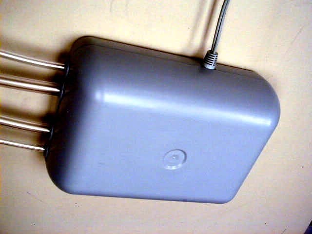
Click to zoom
Application Details
- Equipment Class
- DSC - Part 15 Security/Remote Control Transmitter
- Date of Grant
- Mar 09, 2004
- Application Purpose
- Original Equipment
- Date of Application
- Mar 09, 2004
- Equipment Note
- Firmness Control� System 9000
- Frequency Range
- 418.00000000 - 418.00000000
- Company
- Sleep Number Corporation
- Country
- United States
Documents & Files

Document Text
Text extracted from the exhibit documents filed with the FCC. Open a document above to read the original.
Users Manual
Finding Your Comfort Level Congratulations on the successful assembly of your foundation. Now you are ready to assemble your SLEEP NUMBER ® mattress. It can be quickly and easily completed without tools. Sleep Number ® 9000 Model owners: After completing the foundation assembly instructions in the Owner’s Manual, refer to these mattress assembly and Firmness Control ™ system instructions instead of those in the Owner’s Manual. Sleep Number ® 9000 Model Carefully Check the Contents of Your Mattress Boxes If you are missing any items listed on the following page, please e-mail Customer Service at [email protected] or call 1-800-472-7185. Orientation These instructions refer to “left” and “right” as if you are standing at the head of the bed looking toward the foot of the bed. Prepare Your Foam Pads Carefully open the Foam Comfort Pads and Foam Base Pad and set aside. NOTE: At least 20 minutes of expansion time is needed. before you begin It is wonderful! After only one night, we both commented that we had the best night’s sleep in years! Lowell S. Flagstaff, AZ Congratulations on the successful assembly of your SLEEP NUMBER ® bed. Now you are ready to find your comfort level. Firmness Control ™ system 9000 Unlike innerspring mattresses, a Sleep Number ® bed can be personalized at any time to the changing condition of your body. Some reasons to alter the firmness of your bed include: • strained muscles • back pain • weight change • pregnancy • bad sunburn In addition to personalizing your bed for a great night's sleep, you can also alter the mattress firmness when you wake in the morning in order to: • facilitate getting out of bed, if needed • achieve a “fuller” bed appearance Dual Adjustability If you purchased a dual chamber model, you have the ability to personalize each side of your Sleep Number ® bed. Since no two body types are the same, each sleep partner should find their own comfort level. If your model came with one remote for a dual chamber bed, pressing the “L” button on the remote enables you to make changes to the left side of the bed (left is determined when laying on your back on the bed). before you begin NOTE:A 9-volt battery is included and should last about six months under normal use. Replace the battery when the low battery indicator is displayed. 2 Wired Remotes Firmer (top button) Softer (bottom button) Setting Your Sleep Number ® STEP 1. Lie on The Sleep Number Bed by Select Comfort ™ in your normal sleep position, holding your remote. STEP 2. Press any button on the remote to “wake” it up. (If using the wireless remote with the L and R buttons, press L or R to choose a side.) It will display the current Sleep Number ® setting. If you have an idea of what your Sleep Number ® is, enter it on the remote by pressing the firmer or softer buttons until the number you desire is displayed. The display will go back to your current Sleep Number ® and then the adjustment will begin. The Sleep Number ® and number of reference bars displayed will change as the firmness changes. Remain still until the change is complete. When the adjustment is complete, the Sleep Number ® will stay lit for 5 seconds and then the display will turn off. If you decide to change your Sleep Number ® before the firmness adjustment is complete, just press any button and the Firmness Control ™ system will stop. Then, go to the Sleep Number ® you want. It sometimes takes several nights of sleeping at different settings to discover your ideal Sleep Number ® . If you would like to experiment further with your Sleep Number ® setting, refer to the inside of page 13 in the Owner’s Manual. Follow the step-by-step instructions for the Deluxe Sleep Number ® Firmness Control System ™ . 1 Wireless Remote Firmer (top button) Softer (bottom button) Firmness Control ™ system 9000 Memory Wireless Remote Recalling the Memory • Press the “L" or “R" for the side you'd like to recall. • Press the MEM button 2 times within 5 seconds. The first time you press MEM it will show you the Sleep Number ® currently in the memory setting, the second time it will begin changing the Sleep Number ® to that memory setting. Wired Remote Recalling the Memory • Press the MEM button 2 times within 5 seconds. The first time you press MEM it will show you the Sleep Number ® currently in the memory setting, the second time it will begin changing the Sleep Number ® to that memory setting. Fill Feature This feature will allow you to inflate one or both chambers to a Sleep Number ® of 100. Wireless Remote To Fill Both Chambers • Press and hold the FILL button for at least 2 seconds. The right chamber will fill to 100 then the left chamber will fill to 100. To Fill One Chamber • Press any button to “wake up" the remote. • Press “L" or “R" to determine side to fill. • Press and hold the FILL button for at least 2 seconds. Wired Remote • On one remote, press and hold the FILL button for at least 2 seconds. This chamber will begin filling immediately. • To fill the second chamber, on the other remote, press and hold the FILL button for at least 2 seconds. This chamber will fill to 100 when the first chamber is full. To stop the fill feature at any time, press any button on the remote. Wireless Remote Setting the Memory • Press the “L" or “R" to choose a side and “wake up” the remote. • Adjust the bed to the Sleep Number ® you'd like as your memory setting. • Once at the desired Sleep Number ® , press and hold the MEM button for 3 seconds. • “Memory Set" will appear above the Sleep Number ® when it's set. Wired Remote Setting the Memory • Press the up or down arrow to “wake up" the remote. • Adjust the bed to the Sleep Number ® you'd like as your memory setting. • Once at the desired Sleep Number ® , press and hold the MEM button for 3 seconds. • “Memory Set" will appear above the Sleep Number ® when it's set. Memory Featuremore This feature allows you to set your favorite Sleep Number ® into memory and recall it at any time. Follow …
Text truncated - open the document above for the full version.
Internal Photos
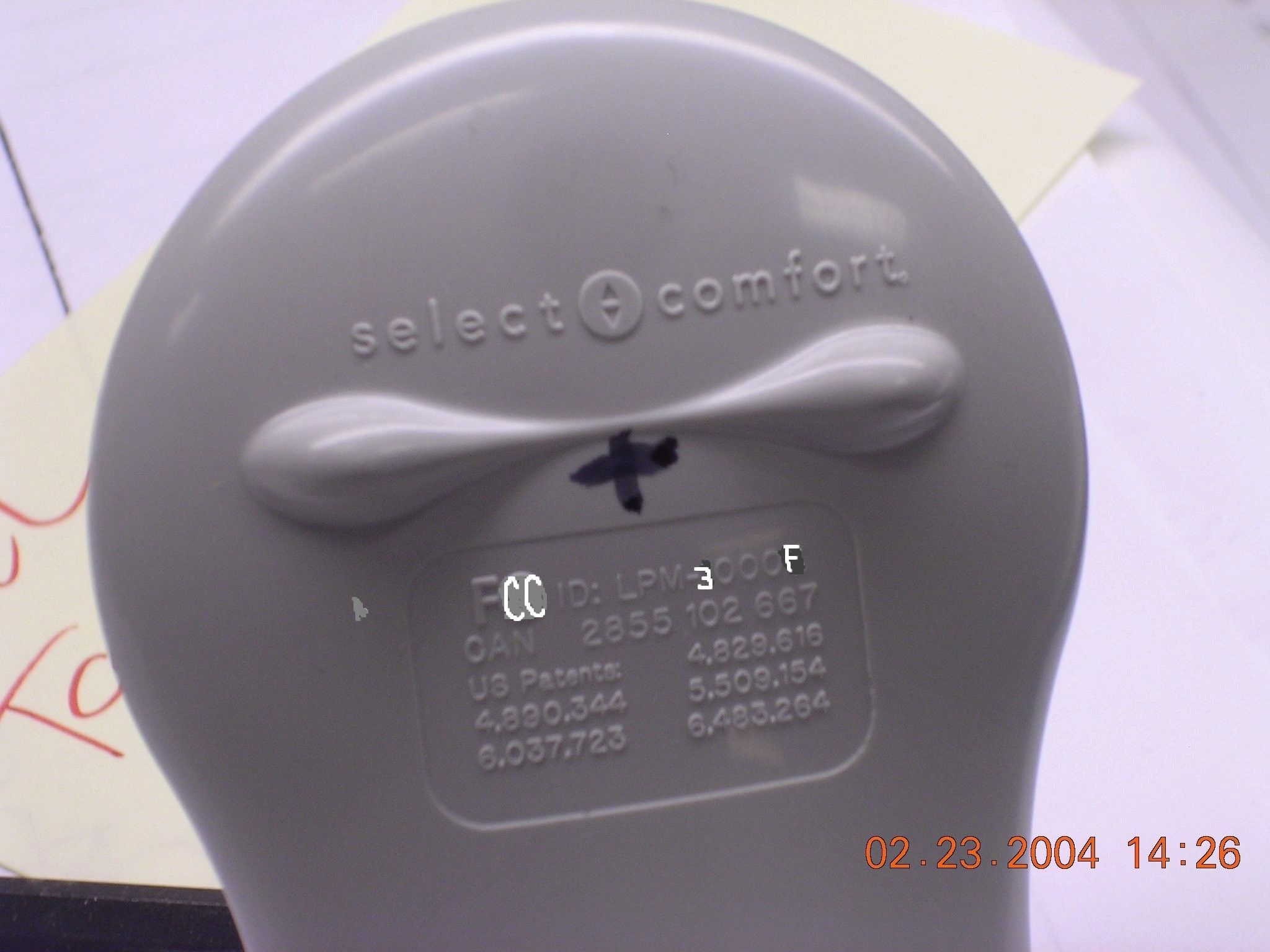
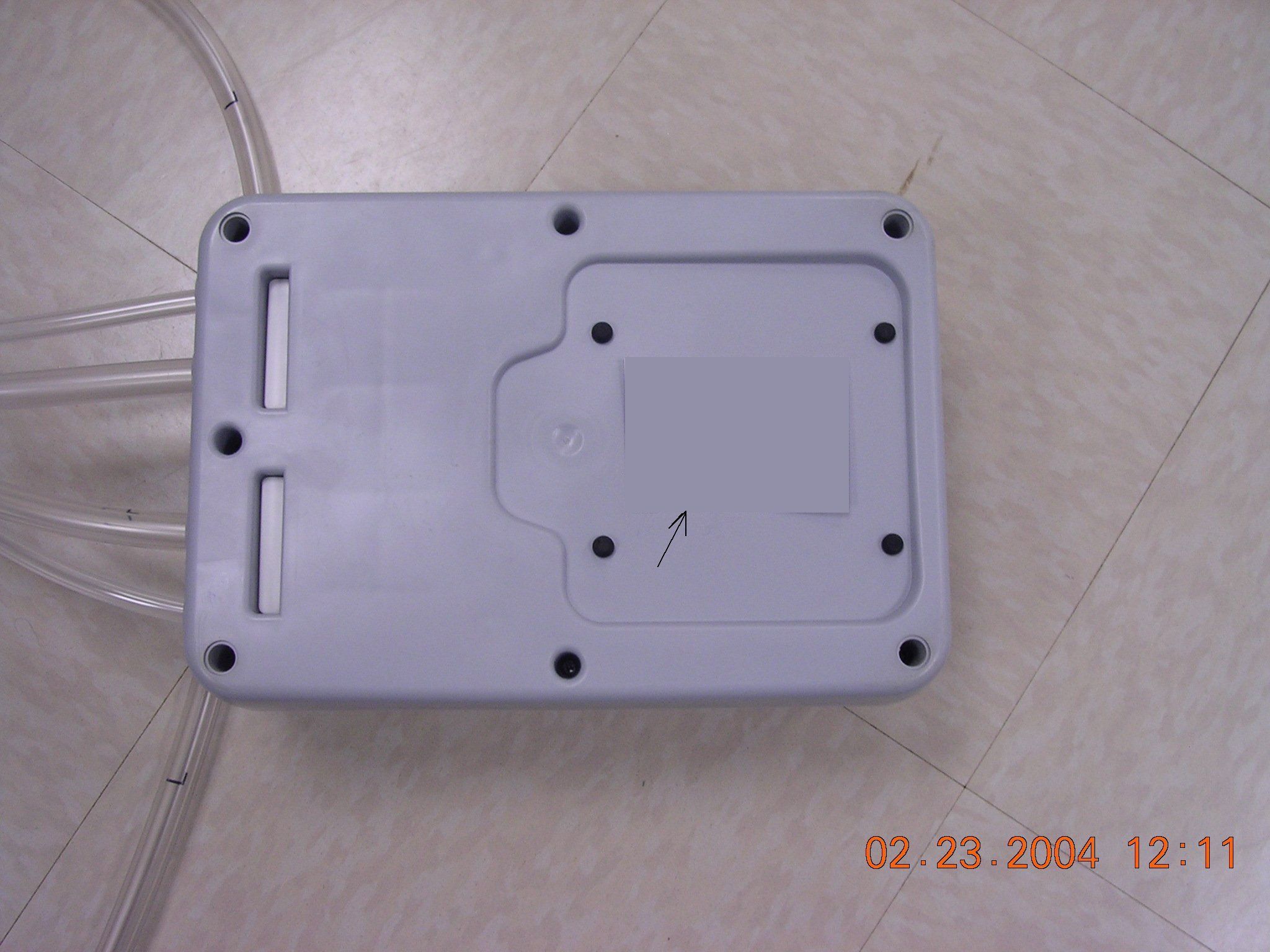
Hand Control Unit Hand Control Unit Base Unit Base Unit Base Unit
Operational Description
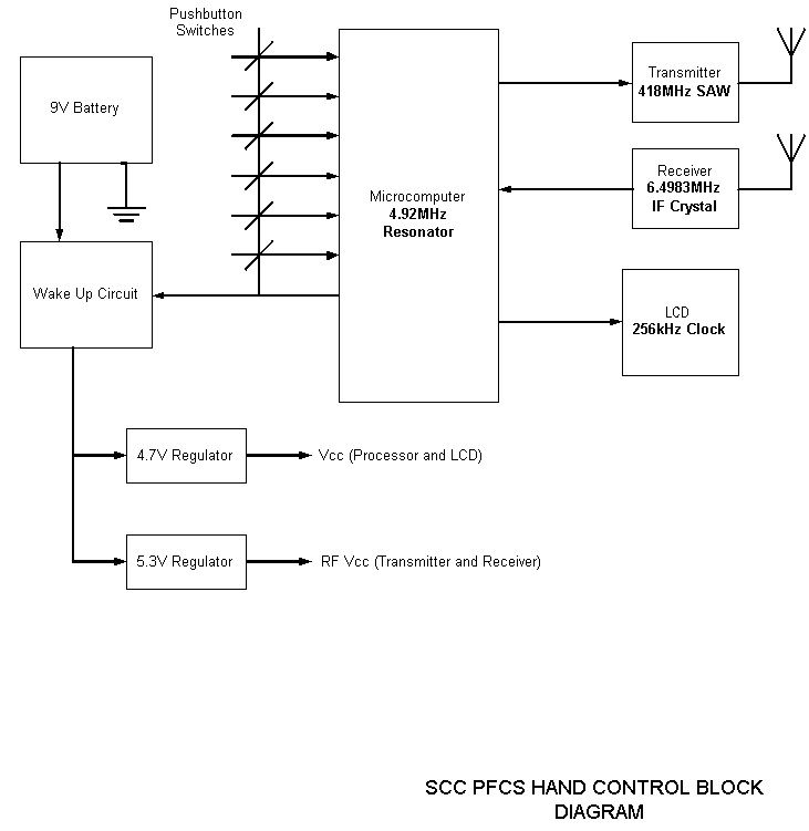
Select Comfort PFCS series RF Hand Control, Circuit Description. Prepared 02/20/04 Power Supply: The Hand Control is powered by a 9 VDC battery. Pushing any button on the Hand Control turns on a transistor that allows voltage to enter the 4.7V regulator giving VCC to the board. A resistor divider off the emitter of the before mentioned transistor provides an enable state to another regulator for the receiver circuit. Controller: A Motorola 68HC908JL3E is used, and is a FLASH based 8 bit processor that operates at a crystal controlled frequency of 4.9152 MHz. The microcomputer has software installed that is capable of operating different mattress configurations. Inputs from six push buttons facilitate an adjustment request that the controller manages. RF Section: The serial communications between the Pump Control and Hand Control is based on a carrier frequency of 418 MHz, established with a SAW Resonator in the transmitter of each control. When an adjustment is initiated by the Hand Control, a packet of information that is 40 bits, and Manchester Coded at 833 Hz, is sent from the Hand Control Transmitter to the Pump Control Receiver. The receiver on the Hand Control is a Micrel MICRF022. This device is a true “antenna-in to data-out” monolithic IC that is run in a Fixed Mode with a 6.4983 IF crystal. While the instruction is in process and waiting for completion, the Pump Control continuously updates the pressure level by sampling the readings on the pressure sensor. As the levels change information is sent back to the Hand Control, at a rate of one packet of information per second. When the adjustment is completed and no further commands are sent the Hand Control enters a sleep mode (approximately 10 seconds after the completed task). The Hand Control stays in this state until a button is pushed to initiate an adjustment. Display: The display is an LCD from Ocular that is customized to our needs. When initiating an adjustment the system is first awakened. The Hand Control by a button push and the Pump Control by receiving a RF prompt from the Hand Control asking for an update from the pressure sensor. The current setting is displayed and adjustments can then be requested. As an adjustment is in process the controller updates the LCD real time and tic marks increase/decrease as the pressure level changes. For every few tic marks changed the sleep number also tracks in increments/decrements of 5. The LCD has it’s own internal clock that is running at 256 kHz.
Operational Description
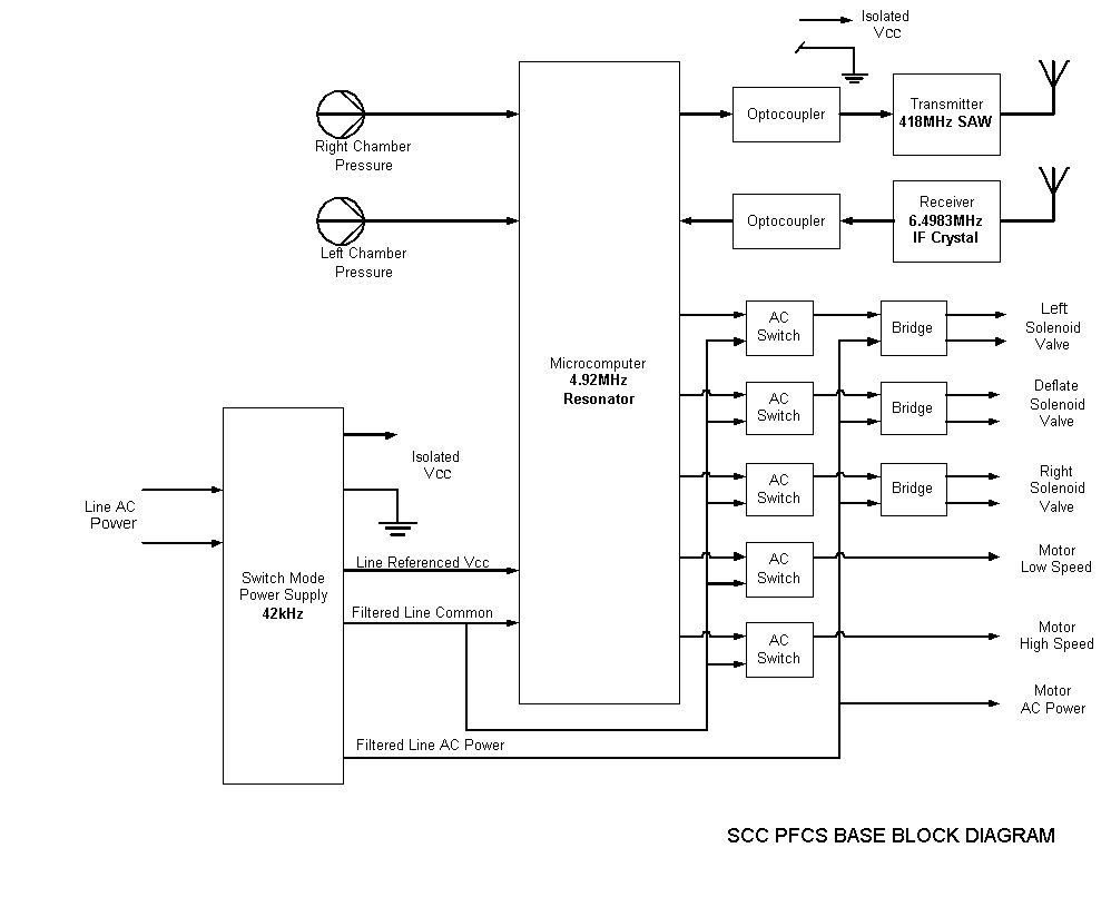
Select Comfort PFCS series RF Pump Control, Circuit Description. Prepared 02/20/04 The Pump Control Circuit adjusts the pressure in a Select Comfort Mattress in response to commands from the RF Hand Control. The circuit Board is powered from ordinary household current and is housed in the Pump/Valve assembly. A Microcomputer manages all the control functions. The board will be equipped with two pressure sensors for a Dual Mattress System and one for a Single. It can operate three solenoid valves (only two active at a time) and a two speed pump. Hand Control serial communications are conducted via an on board RF transceiver. Power Supply: The switched mode power supply using a custom designed EE13 core transformer (LinkSwitch Flyback Design) from Xfrmrs Inc. is designed to operate with input voltages between 85 and 265 VAC at a frequency between 49 and 62 kHz. The power supply’s input circuitry is designed for EMI suppression. Provisions for an Y capacitor between the returns of the transformer’s primary and main 5V windings enable additional suppression. Two isolated 5V windings can supply up to 200mA total current. The pump control’s main 5V supply is regulated using an optically coupled feedback circuit. The pins for the transformer’s secondary 5V supply are located across from the primary and main 5V pins. Switches: The board can switch up to five AC line outputs, two rated for 800mA, and three rated at 200mA. The ST Alternative Current Switch devices used for this task are similar to triacs, but are designed for home appliance applications, and require no added protective circuitry for proper operation. These devices are unique in that a microcomputer port line can be connected to control the gate through a resistor. The device is triggered when current flows from the COM pin (main’s neutral) out the gate. This negative gate current is made possible by connecting the positive side of the controller’s independent 5V supply to the main’s neutral line. When an output port line is forced to a logic”0” the output and connected gate pin will be negative with respect to the main’s neutral line and the switch will turn on. The ST ACS302 low current switch outputs are full wave rectified to operate the off-board DC solenoid valves. Two ST ACS108’s are placed to facilitate the High Speed Fill command, however only one is active for normal compressor operation. Controller: A Motorola 68HC908JL3E is used, and is a FLASH based 8 bit processor that operates at a crystal controlled frequency of 4.9152 MHz. The microcomputer has software installed that is capable of operating different mattress configurations. The outputs of two resistor dividers are measured at power-up to determine the exact nature of the installation. The Motorola MPXV4006GC6T1 gauge type air pressure sensors have amplified and temperature compensated outputs for inputs up to 0.87 PSIG (6kPa). RF Section: The serial communications between the Pump Control and Hand Control is based on a carrier frequency of 418 MHz, established with a SAW Resonator in the transmitter of each control. When an adjustment is initiated by the Hand Control, a packet of information that is 40 bits, and Manchester Coded at 833 Hz, is sent from the Hand Control Transmitter to the Pump Control Receiver. The receiver on the Pump Control is a Micrel MICRF022. This device is a true “antenna-in to data-out” monolithic IC that is run in a Fixed Mode with a 6.4983 IF crystal. The transmitted instruction is relayed to the processor through an Opto Coupler. While the instruction is in process and waiting for completion, the Pump Control continuously updates the pressure level by sampling the readings on the pressure sensor. As the levels change information is sent through the RF transmitter (which is also optically isolated from the processor) back to the Hand Control at a rate of one packet of information per second. When the adjustment is completed and no further commands are sent the Pump Control enters a sleep mode (approximately 20 seconds after the completed task). The Pump Control stays in this state until the Wake-Up flag is tripped in the Receiver IC indicating a RF signal is present and an adjustment is being requested.
Test Report
Winland Electronics Inc. Application For Certification 418MHz PFCS Air Bed Firmness Control System FCC ID: LPM-3000F February 24, 2004 Intertek ETL SEMKO 7250 Hudson Boulevard, Suite 100, Oakdale, MN 51228 Telephone 651-730-1188, Fax 651-730-1282 Home Page www.intertek.com CONTENTS 1.0 GENERAL DESCRIPTION..........................................................................1 1.1 Related Submittals Grants.....................................................................................1 1.2 Product Description............................................................................................1 1.3 Test Methodology..............................................................................................1 1.4 Test Facility.....................................................................................................1 2.0 SYSTEM TEST CONFIGURATION..............................................................2 2.1 Justification......................................................................................................2 2.2 EUT Exercising Software.....................................................................................2 2.3 Special Accessories............................................................................................2 2.4 Equipment Modification.......................................................................................2 2.5 Support Equipment List and Description...................................................................2 2.6 Test Configuration Block Diagrams.........................................................................3 3.0 TEST RESULTS.........................................................................................4 3.1 Transmitting Time, FCC 15.231(a)(1 and 2)..............................................................5 3.2 Field Strength of Fundamental and Spurious Emissions, FCC 15.231(b)............................6 3.2.1 Average Correction Factor Calculation, FCC 15.35 and 15.231(b)(2).......................12 3.3 Bandwidth of Emissions, FCC 15.231(c)................................................................19 3.4 Line Conducted Emissions, FCC 15.207................................................................22 3.5 Test Procedure................................................................................................24 3.6 Field Strength Calculation..................................................................................25 4.0 TEST EQUIPMENT..................................................................................26 FCC ID: LPM-3000F February 2004 Page 1 of 26 1.0 GENERAL DESCRIPTION 1.1 Related Submittals Grants This is single application of the Winland Electronics Inc. 418MHz Air Bed Firmness Control System for Certification under FCC Part 15, Subpart C. There are no other simultaneous applications. The Receiver portion of the System will be verified under Declaration of Conformity. 1.2 Product Description The 418MHz Air Bed Firmness Control System is a RF remote control system operating in 418MHz. The System consists of two periodic operation transceivers: 418MHz Hand Control Unit and 418MHz Base Unit. The intended use of the 418MHz Hand Control Unit is to generate and transmit a RF signal to control 418MHz Base Unit and receive data from the 418MHz Base Unit. The intended use of the 418MHz Base Unit is to receive command from the 418MHz Hand Control Unit, execute this command, and send data about status of the 418MHz Base Unit back to the 418MHz Hand Control Unit. Both the 418MHz Hand Control Unit and the 418MHz Base Unit use identical RF Modules. The 418MHz Hand Control Unit is powered at 9VDC from internal battery. The 418MHz Base Unit powered at 120VAC/60Hz. Antenna Description: Both units have the internal integrated antenna. Sample Submitted: February 17, 2004 Test Work Started: February 17, 2004 Test Work Completed: February 18, 2004 1.3 Test Methodology Emission measurements were performed according to the procedures in ANSI C63.4-2000. All field strength radiated emissions measurements were performed in the semi-anechoic chamber, and for each scan, the procedure for maximizing emissions in Appendices D and E were followed. All field strength radiated tests were performed at an antenna to EUT distance of 3 meters, unless stated otherwise in the "Justification Section" of this Application. 1.4 Test Facility The test site facility used to collect the radiated and conducted measurement data is located at 7250 Hudson Blvd., Suite 100, Oakdale, Minnesota. This test facility has been fully described in a report dated on March 2003 submitted to FCC. Please reference the site registration number: 90706, dated April 18, 2003. FCC ID: LPM-3000F February 2004 Page 2 of 26 2.0 SYSTEM TEST CONFIGURATION 2.1 Justification Each transceiver was tested separately in transmitting mode. For simplicity of testing, each device was wired to transmit continuously for all tests except 15.231(a)(1 and 2) testing. 2.2 EUT Exercising Software N/A 2.3 Special Accessories There are no special accessories necessary for compliance of these products. 2.4 Equipment Modification No modifications were installed during the testing. 2.5 Support Equipment List and Description N/A FCC ID: LPM-3000F February 2004 Page 3 of 26 2.6 Test Configuration Block Diagrams Each EUT was setup as tabletop equipment. The Hand Control Unit was powered at 9VDC from the fresh internal battery. The Base Unit was powered at 120VAC/60Hz. Field Strength Measurements FCC ID: LPM-3000F February 2004 Page 4 of 26 3.0 TEST RESULTS Data is included for the worst case configuration (the configuration which resulted in the highest emission levels). A sample calculation, configuration photographs, data tables and graphical representations of the emissions are included. The EUT is intended for operation under the requirements of Part 15 Subpart C. Specific test requirements include the following: 47 CFR 15.23…
Text truncated - open the document above for the full version.
Test Setup Photos
EXHIBIT 1 CONFIGURATION PHOTOS Radiated Emissions Test Configuration Radiated Emissions Test Configuration Radiated Emissions Test Configuration Radiated Emissions Test Configuration Radiated Emissions Test Configuration Radiated Emissions Test Configuration Conducted Emissions Test Configuration Conducted Emissions Test Configuration
Contact Information
Applicant
Jeff Barnum(VP of Manufacturing Operations)
Technical Contact
Select Comfort CorporationPaul Mahoney
[email protected]763-551-7157
6105 Trenton Lane North · Minneapolis, Minnesota · United States
Non-Technical Contact
Select Comfort CorporationJim Gifft
[email protected]763-551-7000
Test Firm
Intertek Testing ServicesUri Spector
Technical Specifications
| # | Rule Parts | Frequency Range | Power Output |
|---|---|---|---|
| 1 | 15.231 | 418 MHz - 418 MHz | - |
Other Applications from Sleep Number Corporation
LPM-10000
May 20, 2015Smart Outlet
Equipment Class
DTS - Digital Transmission System
LPM-7000A
Feb 23, 2014Sleep monitoring and tracking system with the ability to monitor heart rate, respiration rate, and motion.
Equipment Class
DTS - Digital Transmission System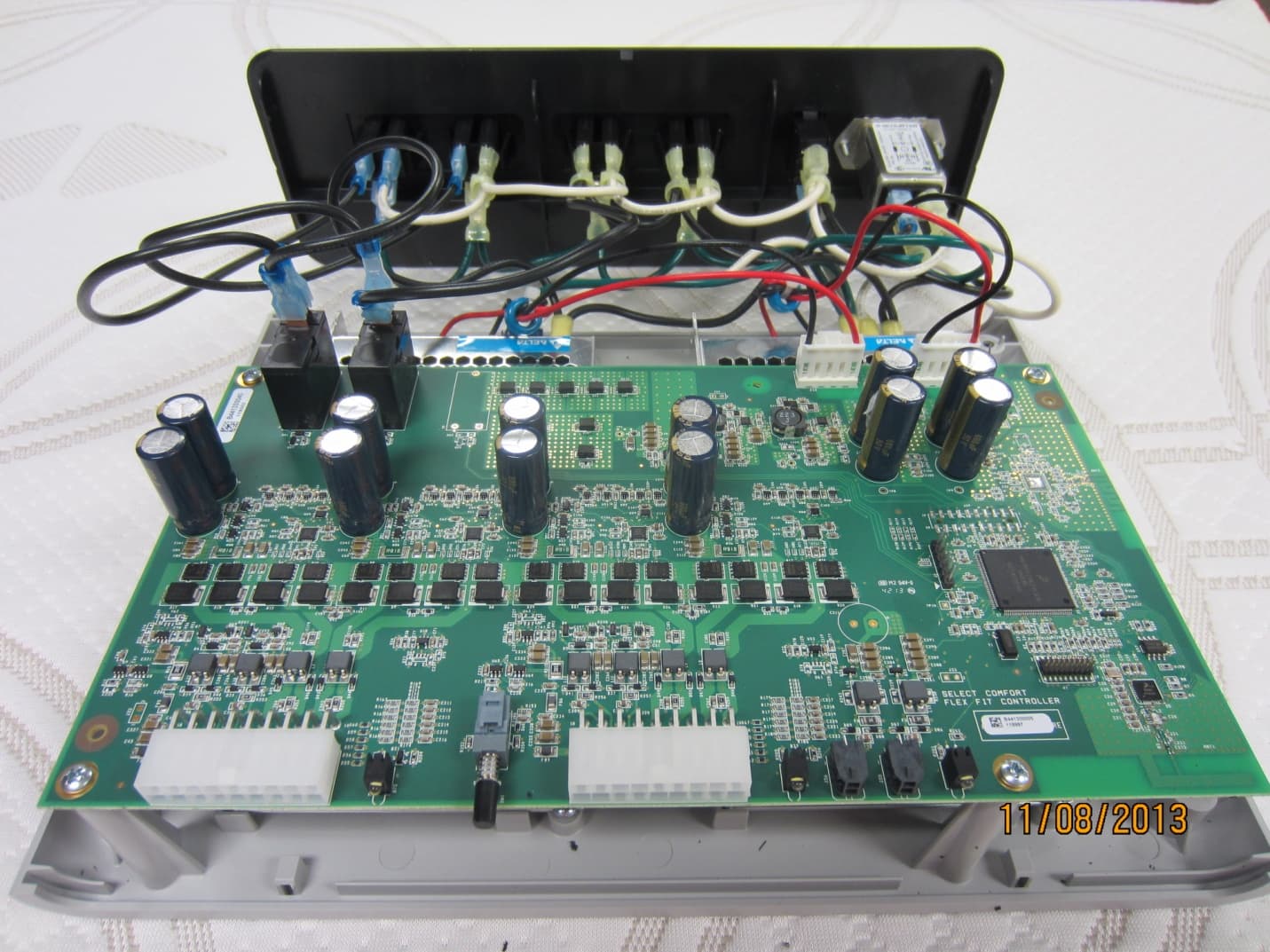
LPM-9000A
Dec 01, 2013Select Comfort Flex Fit
Equipment Class
DTS - Digital Transmission SystemLPM-6000A
Mar 21, 2013Dual Temperature Engine
Equipment Class
DXX - Part 15 Low Power Communication Device Transmitter
LPM-5000A
Mar 10, 2013NXT Remote
Equipment Class
DXX - Part 15 Low Power Communication Device Transmitter