LPM-7000ASleep monitoring and tracking system with the ability to monitor heart rate, respiration rate, and motion.
Sleep Number Corporation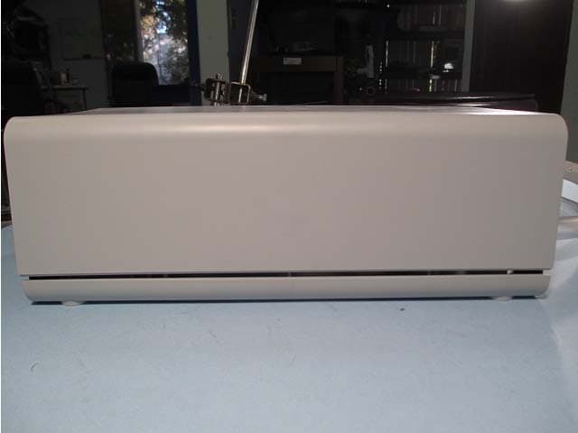
Click to zoom
Application Details
- Equipment Class
- DTS - Digital Transmission System
- Date of Grant
- Feb 23, 2014
- Application Purpose
- Original Equipment
- Date of Application
- Feb 20, 2014
- Equipment Note
- Sleep monitoring and tracking system with the ability to monitor heart rate, respiration rate, and motion.
- Frequency Range
- 2412.00000000 - 2462.00000000
- Company
- Sleep Number Corporation
- Country
- United States
Documents & Files
Document Text
Text extracted from the exhibit documents filed with the FCC. Open a document above to read the original.
Users Manual
With Sleep IQ Firmness control system Setting up yourSleepIQFirmness Control System...............pg4 Wi-Fi Configuration...................................................................pg5 Wi-Fi Troubleshooting...............................................................pg6 pg7 pg12 pg17 pg19 pg21 pg23 pg25 pg28 Sleep IQ Firmness Control™ System •Open the door located above the hose connections on the end of the pump. Inside you will find the Sleep IQ module. Push on it to ensure fully engaged and close the door. •Plug the two voice control modules into the connectors located in between the pump hose ports at the end of the pump. 1 2 3 4 The first two lights on the LED panel will light up to indicate that the power is on and the remote bind window is open. At this time you need to simply grab your remote and the screen should light up and bind automatically to your pump, turning that second light solid 5 6•Unplug the pump and begin Wi-Fi configuration set up 4 Sleep IQ Firmness Control™ System–Wi-Fi Configuration •Remove the USB stick from the pump box and go to a computer or device that both has a USB port and can connect to the internet •Log into URL at: http://uitest.zepp.bamlabs.com/zep_webapp/#/signin •Create your account if you haven’t already done so utilizing the link and log on information you received via email when you purchased your bed •Go to the account admin screen and enter in your home Wi-Fi network name and password. Be careful to use correct capitalization, spacing and spelling. For example, “NetworkName” versus “Networkname” versus “networkname” and “network-name” are all different! •Plug your USB stick into your computer •Select the “download Wi-Fi key” and save the file to your USB stick •Safely remove the USB stick from your computer and return to your pump •Unplug your pump from the wall •Open up the plastic door above the hose connections. In the Sleep IQ module you will see a USB port on the left hand side (see photo to the right). Plug your USB stick into the USB drive on the Sleep IQ module •Plug the pump back into the wall •Once powered on your pump will begin booting and connect to your home Wi-Fi •When all 5 of the LED lights are on you can remove the USB stick from the pump. To do so place a finger on the Sleep IQ module to ensure the connection between the module and the pump remains engaged Go to Wi-Fi troubleshooting for issues or questions regarding installation USB Port 5 Sleep IQ Firmness Control™ System–Wi-Fi Troubleshooting LightOnBlinkingOffTry this 1 Pump is receiving powerPump is booting upNo power to pumpCheck power connections 2 Pump is working and bound to a remote Remote attempting to bind Pump Non- Functional Rebindyourremote 3 Pump computer is connected to your home network Attempting to connect to your network No connection to your home network Return to your account settings and re- enter your networkname and password. Pay attention to case, spelling and spaces CheckWifistrength inyour bedroom using another device 4 Pump connected to Internet n/aNo internet connection Try to connect to internet with another device on your network 5 Data sent and received from your pump via the internet Establishing contactNo connection to your account via the internet Return to your account settings and re- enter your network and password. Pay attention to case, spelling and spaces If you experience further issues, please contact Customer Service at the number listed in the back of this manual 6 Voice control module22 7 Sleep IQ Firmness Control System 8 8 Voice Control Modules (2) 9 10 11 12 13 14 15 16 17 18 19 20 23 24 The equipment described in this guide has been tested and found compliant with the limits for a Class B digital device, pursuant to Part 15 of the FCC rules. These limits are designed to provide reasonable protection against harmful interference when the equipment is operated in a commercial environment. This equipment generates, uses, and can radiate radio frequency energy and if not installed and used in accordance with the instruction manual, may cause harmful interference to radio communications. However, there is no guarantee that interference will not occur in a particular installation. If this equipment does cause harmful interference to radio or television reception, which can be determined by turning the equipment off and on, the user is encouraged to try to correct the interference by one or more of the following measures: •Reorient or relocate the receiving antenna . •Increase the separation between the equipment and receiver. •Connect the equipment into an outlet on a circuit different from that which the receiver is connected. •Consult the dealer or an experienced radio/TV technician for help. Warning: Any attempt to make changes or modifications could void the user’s authority to operate the equipment according to FCC certification. 25 26 27 28
ID Label/Location Info
Select Comfort Corporation Model: SIQ03NNNN MATTRESS INFLATOR Build Date: NN/NN/NN HOUSEHOLD USE ONLY 120 Volts 0.25 Amp 60 Hz CAN 2855 102 669 Mac Address Bar Code AIR COMPRESSORS PH35 CAUTION: To Reduce the Risk of Electric Shock or Injury, use Indoors Only To prevent electric shock, do not remove cover. No user serviceable parts inside. Refer servicing to qualified personnel. Protected by one or more of the following US Patents: 4,829,616 & 4,890,344 & 5,509,154 & 5,904,172 & 5,903,941 & 6,037,723 & 6,202, 239 & 6,397,419 & 6,483,264 XXNNXNNNNNNX Pump Serial Number Bar Code XXNNXNNNNNNX This device complies with Part 15 of FCC Rules. Operation is subject to the following two conditions: (1) this device may not cause harmful interference, and (2) this device must accept any interference received, including interference that may cause undesired operation. FCC ID: LPM-7000A
Internal Photos
EXTERNAL PHOTOS Company Name LS Research, LLC Model # TiWi‐R2 FCC ID # TFB‐TIWI1‐01 IC # 5969A‐TIWI101 Page 1 of 1 Front side of TiWi‐R2 Module Back side of TiWi‐R2 Module
Internal Photos
INTERNAL PHOTOS Company Name LS Research, LLC Model # TiWi1‐R1 FCC ID # TFB‐TIWI1‐01 IC # 5969A‐TIWI101 Page 1 of 1 Module with Shield Removed
Test Report
This report contains a total of 146 pages and may be reproduced in full only. Partial reproduction may only be done with the written consent of CKC Laboratories, Inc. Bam Labs ADDENDUM TEST REPORT TO 94232-14 Household Air Mattress Inflator Model: SIQ XX00DR Tested To The Following Standards: FCC Part 15 Subpart C Sections 15.207, 15.247 and RSS 210 Issue 8 Report No.: 94232-14A Date of issue: February 7, 2014 This test report bears the accreditation symbol indicating that the testing performed herein meets the test and reporting requirements of ISO/IEC 17025 under the applicable scope of EMC testing for CKC Laboratories, Inc. We strive to create long-term, trust based relationships by providing sound, adaptive, customer first testing services. We embrace each of our customers’ unique EMC challenges, not as an interruption to set processes, but rather as the reason we are in business. Page 2 of 146 Report No.: 94232-14A TABLE OF CONTENTS Administrative Information .......................................................................................................................... 3 Test Report Information ............................................................................................................................................ 3 Revision History ......................................................................................................................................................... 3 Report Authorization ................................................................................................................................................. 3 Test Facility Information ............................................................................................................................................ 4 Software Versions ...................................................................................................................................................... 4 Site Registration & Accreditation Information .......................................................................................................... 4 Summary of Results ................................................................................................................................................... 5 Conditions During Testing.......................................................................................................................................... 5 Equipment Under Test ............................................................................................................................................... 6 Peripheral Devices ..................................................................................................................................................... 6 FCC Part 15 Subpart C ................................................................................................................................... 7 15.207 AC Conducted Emissions ................................................................................................................................ 7 15.247(b)(3) RF Power Output ................................................................................................................................ 32 15.31(e) Voltage Variations ..................................................................................................................................... 43 -6dBc Occupied Bandwidth ..................................................................................................................................... 46 RSS-210 / 99% OBW and -6dB EBW Required ......................................................................................................... 53 15.247(d) Field Strength of Spurious Emissions ...................................................................................................... 64 Band Edge .............................................................................................................................................................. 131 15.247(e) Power Spectral Density ......................................................................................................................... 138 Supplemental Information ........................................................................................................................ 145 Measurement Uncertainty .................................................................................................................................... 145 Emissions Test Details ............................................................................................................................................ 145 Page 3 of 146 Report No.: 94232-14A ADMINISTRATIVE INFORMATION Test Report Information REPORT PREPARED FOR: REPORT PREPARED BY: Bam Labs 901 Campisi Way Campbell, CA 95008 Morgan Tramontin CKC Laboratories, Inc. 5046 Sierra Pines Drive Mariposa, CA 95338 Representative: Todd Austin / P. Carter - SEL Project Number: 94232 Customer Reference Number: SELc350 DATE OF EQUIPMENT RECEIPT: August 20, 2013 DATE(S) OF TESTING: August 20-23, 2013 Revision History Original: Testing of the Household Air Mattress Inflator, SIQ XX00DR to FCC Part 15 Subpart C Sections 15.207, 15.247 and RSS 210 Issue 8. Addendum A: To correct the gain of the antenna in the test conditions for all sections, re-calculated the RF power and power density and corrected 138VVDC to 138V in the test conditions notes of section 15.31(e) Voltage Variations. Report Authorization The test data contained in this report documents the observed testing parameters pertaining to and are relevant for only the sample equipment tested in the agreed upon operational mode(s) and configuration(s) as identified herein. Compliance assessment remains the client’s responsibility. This report may not be used to claim product endorsement by A2LA or any government agencies. This test report has been authorized for release under quality contro…
Text truncated - open the document above for the full version.
Test Report
Page 64 of 146 Report No.: 94232-14A 15.247(d) Field Strength of Spurious Emissions Test Data Sheets Test Location: CKC Laboratories, Inc. • 1120 Fulton Place • Fremont, CA 94539 • (510) 249-1170 Customer: Bam Labs Specification: 15.247(d) / 15.209 Radiated Spurious Emissions Work Order #: 94232 Date: 8/22/2013 Test Type: Radiated Scan Time: 15:41:25 Equipment: Household Air Mattress Inflator Sequence#: 87 Manufacturer: Bam Labs Tested By: Hieu Song Nguyenpham Model: SIQ XX00DR S/N: CC 04 B4 00 00 8F Test Equipment: ID Asset # Description Model Calibration Date Cal Due Date T1 AN00432 Loop Antenna 6502 4/2/2013 4/2/2015 T2 ANP00880 Cable RG214U 7/30/2012 7/30/2014 T3 ANP05300 Cable RG214/U 3/25/2013 3/25/2015 AN02668 Spectrum Analyzer E4446A 2/22/2013 2/22/2015 Equipment Under Test (* = EUT): Function Manufacturer Model # S/N Household Air Mattress Inflator* Bam Labs SIQ XX00DR CC 04 B4 00 00 8F Support Devices: Function Manufacturer Model # S/N Test Conditions / Notes: Radiated Spurious Emission Frequency Range: 9kH to 30 MHz High Clock: 32MHz Firmware used: SmartPump 501E (0.80d30), BLE v1.1.11, SleepExpert 8.00-d10rc2 Temperature: 21.6°C, Humidity: 39%, Atmospheric Pressure: 101.4kPa Transmitter operating frequency: 2.4GHz Low Frequency: 2.402GHz, Middle Frequency: 2.440GHz, High Frequency: 2.480GHZ RF Output of the chip = 0dBm Gain of the antenna = 1dBi 9 kHz -150 kHz; RBW=200 Hz, VBW=200 Hz; 150 kHz-30 MHz; RBW=9 kHz, VBW=9 kHz; 30 MHz-1000 MHz; RBW=120 kHz, VBW=120 kHz, 1000 MHz-25000MHz; RBW=1 MHz, VBW=1 MHz. The EUT is a fixed device. It is placed on the 80 cm table. The EUT is set to continuously transmit. Note: Bluetooth is operated only. Low Channel Page 65 of 146 Report No.: 94232-14A Ext Attn: 0 dB Measurement Data: Reading listed by margin. Test Distance: 3 Meters # Freq Rdng T1 T2 T3 Dist Corr Spec Margin Polar MHz dBμV dB dB dB dB Table dBμV/m dBμV/m dB Ant 1 674.766k 37.8 +9.9 +0.1 +0.0 -40.0 7.8 31.0 -23.2 Perpe 2 509.601k 39.5 +9.8 +0.1 +0.0 -40.0 9.4 33.5 -24.1 Paral 3 902.653k 33.8 +9.5 +0.1 +0.0 -40.0 3.4 28.5 -25.1 Perpe 4 896.381k 33.9 +9.5 +0.1 +0.0 -40.0 3.5 28.6 -25.1 Paral 5 1.076M 31.8 +9.7 +0.1 +0.0 -40.0 1.6 27.0 -25.4 Perpe 6 1.467M 28.8 +9.8 +0.1 +0.0 -40.0 -1.3 24.3 -25.6 Paral Page 66 of 146 Report No.: 94232-14A Test Location: CKC Laboratories, Inc. • 1120 Fulton Place • Fremont, CA 94539 • (510) 249-1170 Customer: Bam Labs Specification: 15.247(d) / 15.209 Radiated Spurious Emissions Work Order #: 94232 Date: 8/22/2013 Test Type: Radiated Scan Time: 11:43:15 Equipment: Household Air Mattress Inflator Sequence#: 72 Manufacturer: Bam Labs Tested By: Hieu Song Nguyenpham Model: SIQ XX00DR S/N: CC 04 B4 00 00 8F Test Equipment: ID Asset # Description Model Calibration Date Cal Due Date T1 AN00730 Preamp 8447D 1/17/2013 1/17/2015 T2 AN00852 Biconilog Antenna CBL 6111C 11/28/2012 11/28/2014 T3 ANP00880 Cable RG214U 7/30/2012 7/30/2014 T4 ANP01183 Cable CNT-195 10/24/2011 10/24/2013 T5 ANP05300 Cable RG214/U 3/25/2013 3/25/2015 AN02668 Spectrum Analyzer E4446A 2/22/2013 2/22/2015 Equipment Under Test (* = EUT): Function Manufacturer Model # S/N Household Air Mattress Inflator* Bam Labs SIQ XX00DR CC 04 B4 00 00 8F Support Devices: Function Manufacturer Model # S/N Test Conditions / Notes: Radiated Spurious Emission Frequency Range: 30MHz to 1000MHz High Clock: 32MHz Firmware used: SmartPump 501E (0.80d30), BLE v1.1.11, SleepExpert 8.00-d10rc2 Temperature: 21.6°C, Humidity: 39%, Atmospheric Pressure: 101.4kPa Transmitter operating frequency: 2.4GHz Low Frequency: 2.402GHz, Middle Frequency: 2.440GHz, High Frequency: 2.480GHz RF Output of the chip = 0dBm Gain of the antenna = 1dBi 9 kHz -150 kHz; RBW=200 Hz, VBW=200 Hz; 150 kHz-30 MHz; RBW=9 kHz, VBW=9 kHz; 30 MHz-1000 MHz; RBW=120 kHz, VBW=120 kHz, 1000 MHz-25000MHz; RBW=1 MHz, VBW=1 MHz. The EUT is a fixed device. It is placed on the 80 cm table. The EUT is set to continuously transmit. Note: Bluetooth is operated only. Low Channel Page 67 of 146 Report No.: 94232-14A Ext Attn: 0 dB Measurement Data: Reading listed by margin. Test Distance: 3 Meters # Freq Rdng T1 T5 T2 T3 T4 Dist Corr Spec Margin Polar MHz dBμV dB dB dB dB Table dBμV/m dBμV/m dB Ant 1 944.401M 36.8 -27.1 +0.9 +23.5 +3.5 +1.0 +0.0 38.6 46.0 -7.4 Horiz 2 30.200M 38.1 -27.1 +0.1 +18.3 +0.5 +0.2 +0.0 30.1 40.0 -9.9 Vert 3 41.180M 40.2 -27.0 +0.2 +12.8 +0.6 +0.1 +0.0 26.9 40.0 -13.1 Vert 4 546.398M 36.5 -26.9 +0.7 +19.1 +2.5 +0.6 +0.0 32.5 46.0 -13.5 Horiz 5 313.125M 42.1 -27.0 +0.5 +13.1 +1.8 +0.4 +0.0 30.9 46.0 -15.1 Horiz 6 266.399M 41.1 -27.0 +0.4 +13.8 +1.7 +0.4 +0.0 30.4 46.0 -15.6 Vert Page 68 of 146 Report No.: 94232-14A Test Location: CKC Laboratories, Inc. • 1120 Fulton Place • Fremont, CA 94539 • (510) 249-1170 Customer: Bam Labs Specification: 15.247(d) / 15.209 Radiated Spurious Emissions Work Order #: 94232 Date: 8/20/2013 Test Type: Radiated Scan Time: 15:27:52 Equipment: Household Air Mattress Inflator Sequence#: 9 Manufacturer: Bam Labs Tested By: Hieu Song Nguyenpham Model: SIQ XX00DR S/N: CC 04 B4 00 00 8F Test Equipment: ID Asset # Description Model Calibration Date Cal Due Date T1 AN02157 Horn Antenna-ANSI C63.5 3115 1/23/2013 1/23/2015 T2 AN03302 Cable 32026-29094K- 29094K-72TC 3/21/2012 3/21/2014 T3 ANP01210 Cable FSJ1P-50A-4A 2/19/2013 2/19/2015 AN02668 Spectrum Analyzer E4446A 2/22/2013 2/22/2015 T4 AN03114 Preamp AMF-7D- 00101800-30-10P 4/11/2013 4/11/2015 T5 AN03015 Cable 32022-2-29094K- 24TC 5/6/2013 5/6/2015 T6 AN03309 High Pass Filter 11SH10- 3000/T10000- O/O 6/12/2012 6/12/2014 Equipment Under Test (* = EUT): Function Manufacturer Model # S/N Household Air Mattress Inflator* Bam Labs SIQ XX00DR CC 04 B4 00 00 8F Support Devices: Function Manufacturer Model # S/N Test Conditions / Notes: Radiated Spurious Emission Frequency Range: 1000MHz to 12000MHz High Clock: 32MHz Firmware used: SmartPump 501E (0.80d30), BLE v1.1.11, SleepExpert 8.00-d10rc2 Temperature: 21.6°C, Humidity: 39%, Atmospheric Pressure: 101.4kPa Trans…
Text truncated - open the document above for the full version.
Test Report
Page 104 of 146 Report No.: 94232-14A Ext Attn: 0 dB Measurement Data: Reading listed by margin. Test Distance: 3 Meters # Freq Rdng T1 T2 T3 T4 Dist Corr Spec Margin Polar MHz dBμV dB dB dB dB Table dBμV/m dBμV/m dB Ant 1 24153.000 M 46.8 +4.4 +5.5 -17.5 +2.9 +0.0 42.1 54.0 -11.9 Horiz 2 23663.000 M 45.4 +4.4 +5.4 -17.7 +3.0 +0.0 40.5 54.0 -13.5 Horiz 3 20905.000 M 44.7 +4.2 +5.1 -17.0 +3.1 +0.0 40.1 54.0 -13.9 Vert 4 23719.000 M 44.7 +4.4 +5.5 -17.7 +3.0 +0.0 39.9 54.0 -14.1 Vert 5 21920.000 M 44.0 +4.3 +5.3 -17.3 +3.0 +0.0 39.3 54.0 -14.7 Horiz 6 18168.000 M 43.4 +3.3 +4.8 -16.9 +3.4 +0.0 38.0 54.0 -16.0 Vert Page 105 of 146 Report No.: 94232-14A Test Location: CKC Laboratories, Inc. • 1120 Fulton Place • Fremont, CA 94539 • (510) 249-1170 Customer: Bam Labs Specification: 15.247(d) / 15.209 Radiated Spurious Emissions Work Order #: 94232 Date: 8/22/2013 Test Type: Radiated Scan Time: 16:12:45 Equipment: Household Air Mattress Inflator Sequence#: 93 Manufacturer: Bam Labs Tested By: Hieu Song Nguyenpham Model: SIQ XX00DR S/N: CC 04 B4 00 00 8F Test Equipment: ID Asset # Description Model Calibration Date Cal Due Date T1 AN00432 Loop Antenna 6502 4/2/2013 4/2/2015 T2 ANP00880 Cable RG214U 7/30/2012 7/30/2014 T3 ANP05300 Cable RG214/U 3/25/2013 3/25/2015 AN02668 Spectrum Analyzer E4446A 2/22/2013 2/22/2015 Equipment Under Test (* = EUT): Function Manufacturer Model # S/N Household Air Mattress Inflator* Bam Labs SIQ XX00DR CC 04 B4 00 00 8F Support Devices: Function Manufacturer Model # S/N Test Conditions / Notes: Radiated Spurious Emission Frequency Range: 9kHz to 30MHz High Clock: 32MHz Firmware used: SmartPump 501E (0.80d30), BLE v1.1.1, SleepExpert 8.00-d10rc2 Temperature: 21.6°C, Humidity: 39%, Atmospheric Pressure: 101.4kPa Transmitter operating frequency: 2.4GHz Number of Channel: 16 Low Frequency: 2.405GHz, Middle Frequency: 2.440GHz, High Frequency: 2.480GHz RF output power of the chip= 1.19 dBm (DC) Gain of the antenna = 1dBi 9 kHz -150 kHz; RBW=200 Hz, VBW=200 Hz; 150 kHz-30 MHz; RBW=9 kHz, VBW=9 kHz; 30 MHz-1000 MHz; RBW=120 kHz, VBW=120 kHz, 1000 MHz-25000MHz; RBW=1 MHz, VBW=1 MHz. The EUT is a fixed device. It is placed on the 80 cm table. The EUT is set to continuously transmit. Note: Zigbee is operated only. Middle Channel Page 106 of 146 Report No.: 94232-14A Ext Attn: 0 dB Measurement Data: Reading listed by margin. Test Distance: 3 Meters # Freq Rdng T1 T2 T3 Dist Corr Spec Margin Polar MHz dBμV dB dB dB dB Table dBμV/m dBμV/m dB Ant 1 718.671k 37.4 +9.8 +0.1 +0.0 -40.0 7.3 30.5 -23.2 Perpe 2 687.310k 37.6 +9.9 +0.1 +0.0 -40.0 7.6 30.9 -23.3 Paral 3 513.782k 39.2 +9.8 +0.1 +0.0 -40.0 9.1 33.4 -24.3 Paral 4 921.469k 33.1 +9.5 +0.1 +0.0 -40.0 2.7 28.3 -25.6 Perpe 5 1.085M 31.5 +9.7 +0.1 +0.0 -40.0 1.3 26.9 -25.6 Paral 6 1.503M 27.8 +9.8 +0.1 +0.0 -40.0 -2.3 24.1 -26.4 Perpe Page 107 of 146 Report No.: 94232-14A Test Location: CKC Laboratories, Inc. • 1120 Fulton Place • Fremont, CA 94539 • (510) 249-1170 Customer: Bam Labs Specification: 15.247(d) / 15.209 Radiated Spurious Emissions Work Order #: 94232 Date: 8/22/2013 Test Type: Radiated Scan Time: 10:26:00 Equipment: Household Air Mattress Inflator Sequence#: 66 Manufacturer: Bam Labs Tested By: Hieu Song Nguyenpham Model: SIQ XX00DR S/N: CC 04 B4 00 00 8F Test Equipment: ID Asset # Description Model Calibration Date Cal Due Date T1 AN00730 Preamp 8447D 1/17/2013 1/17/2015 T2 AN00852 Biconilog Antenna CBL 6111C 11/28/2012 11/28/2014 T3 ANP00880 Cable RG214U 7/30/2012 7/30/2014 T4 ANP01183 Cable CNT-195 10/24/2011 10/24/2013 T5 ANP05300 Cable RG214/U 3/25/2013 3/25/2015 AN02668 Spectrum Analyzer E4446A 2/22/2013 2/22/2015 Equipment Under Test (* = EUT): Function Manufacturer Model # S/N Household Air Mattress Inflator* Bam Labs SIQ XX00DR CC 04 B4 00 00 8F Support Devices: Function Manufacturer Model # S/N Test Conditions / Notes: Radiated Spurious Emission Frequency Range: 30MHz to 1000MHz High Clock: 32MHz Firmware used: SmartPump 501E (0.80d30), BLE v1.1.1, SleepExpert 8.00-d10rc2 Temperature: 21.6°C, Humidity: 39%, Atmospheric Pressure: 101.4kPa Transmitter operating frequency: 2.4GHz Number of Channel: 16 Low Frequency: 2.405GHz, Middle Frequency: 2.440GHz, High Frequency: 2.480GHz RF output power of the chip= 1.19 dBm (DC) Gain of the antenna = 1dBi 9 kHz -150 kHz; RBW=200 Hz, VBW=200 Hz;150 kHz-30 MHz; RBW=9 kHz, VBW=9 kHz; 30 MHz-1000 MHz; RBW=120 kHz, VBW=120 kHz, 1000 MHz-25000MHz;RBW=1 MHz, VBW=1 MHz. The EUT is a fixed device. It is placed on the 80 cm table. The EUT is set to continuously transmit. Note: Zigbee is operated only. Middle Channel Page 108 of 146 Report No.: 94232-14A Ext Attn: 0 dB Measurement Data: Reading listed by margin. Test Distance: 3 Meters # Freq Rdng T1 T5 T2 T3 T4 Dist Corr Spec Margin Polar MHz dBμV dB dB dB dB Table dBμV/m dBμV/m dB Ant 1 716.128M 41.3 -26.7 +0.8 +20.7 +3.0 +0.7 +0.0 39.8 46.0 -6.2 Vert 2 957.111M 37.4 -27.1 +0.9 +23.5 +3.5 +1.0 +0.0 39.2 46.0 -6.8 Vert 3 482.615M 44.3 -26.9 +0.6 +17.5 +2.3 +0.5 +0.0 38.3 46.0 -7.7 Vert 4 904.116M 36.7 -27.1 +0.9 +23.0 +3.4 +1.0 +0.0 37.9 46.0 -8.1 Horiz 5 40.448M 39.2 -27.0 +0.2 +13.2 +0.6 +0.1 +0.0 26.3 40.0 -13.7 Vert 6 546.398M 35.6 -26.9 +0.7 +19.1 +2.5 +0.6 +0.0 31.6 46.0 -14.4 Horiz 7 147.840M 42.4 -26.9 +0.3 +11.0 +1.2 +0.3 +0.0 28.3 43.5 -15.2 Horiz Page 109 of 146 Report No.: 94232-14A Test Location: CKC Laboratories, Inc. • 1120 Fulton Place • Fremont, CA 94539 • (510) 249-1170 Customer: Bam Labs Specification: 15.247(d) / 15.209 Radiated Spurious Emissions Work Order #: 94232 Date: 8/21/2013 Test Type: Radiated Scan Time: 11:32:58 Equipment: Household Air Mattress Inflator Sequence#: 21 Manufacturer: Bam Labs Tested By: Hieu Song Nguyenpham Model: SIQ XX00DR S/N: CC 04 B4 00 00 8F Test Equipment: ID Asset # Description Model Calibration Date Cal Due Date T1 AN02157 Horn Antenna-ANSI C63.5 3115 1/23/2013 1/23/2015 T2 AN03302 Cable 32026-29094K- 29094K-72TC 3/21/2012 3/21/2014 T3 ANP01210 Cable FSJ1P-50A-4A 2/19/2013 2…
Text truncated - open the document above for the full version.
Test Report
W66 N220 Commerce Court ● Cedarburg, WI 53012 ● USA Phone: 262.375.4400 ● Fax: 262.375.4248 www.lsr.com TEST REPORT # 313276 LSR Job #: C-1833 Compliance Testing of: SIQ Wireless Base Unit Test Date(s): October 28-31, 2013 Prepared For: Attn: Rob Nunn Select Comfort 9800 59 th Ave North Minneapolis, MN 55442 In accordance with: Federal Communications Commission (FCC) Part 15, Subpart C, Section 15.247 Industry Canada (IC) RSS 210 Annex 8 Digital Modulation Transmitters (DTS) Operating in the Frequency Band 2400 MHz – 2483.5 MHz This Test Report is issued under the Authority of: Peter Feilen, EMC Engineer Signature: Date: 12/11/13 Test Report Reviewed by: Ryan Urness, Laboratory Quality and Operations Manager Signature: Date: 12/9/13 Tested by: Peter Feilen, EMC Engineer Signature: Date: 10/31/13 This Test Report may not be reproduced, except in full, without written approval of LS Research, LLC. Prepared For: Select Comfort EUT: SIQ Wireless Base Unit LS Research, LLC Report #: 313276 Model #: SIQ01VCSEDR LSR Job #: C-1833 Radiated Sample: 3-028956 Conducted Sample: 3-028864 Page 2 of 65 Contents EXHIBIT 1. INTRODUCTION .........................................................................................................................4 1.1 Scope ................................................................................................................................................4 1.2 Normative References ......................................................................................................................4 1.3 LS Research, LLC Test Facility .......................................................................................................5 1.4 Location of Testing ..........................................................................................................................5 1.5 Test Equipment Utilized ..................................................................................................................5 EXHIBIT 2. PERFORMANCE ASSESSMENT ...............................................................................................6 2.1 Client Information .............................................................................................................................6 2.2 Equipment Under Test Information ..................................................................................................6 2.3 Associated Antenna Description .......................................................................................................6 2.4 EUT’S Technical Specifications ......................................................................................................7 2.5 Product Description .........................................................................................................................8 EXHIBIT 3. EUT OPERATING CONDITIONS & CONFIGURATIONS DURING TESTS ...................9 3.1 Climate Test Conditions...................................................................................................................9 3.2 Applicability & Summary of EMC Emission Test Results..............................................................9 3.3 Modifications Incorporated In The EUT For Compliance Purposes ...............................................9 3.4 Deviations & Exclusions From Test Specifications .........................................................................9 EXHIBIT 4. DECLARATION OF CONFORMITY .................................................................................. 10 EXHIBIT 5. RADIATED EMISSIONS TEST ........................................................................................... 11 5.1 Test Setup ....................................................................................................................................... 11 5.2 Test Procedure ............................................................................................................................... 11 5.3 Test Equipment Utilized ................................................................................................................ 12 5.4 Test Results ...................................................................................................................................... 12 5.5 Calculation of Radiated Emissions Limits ..................................................................................... 13 5.6 Radiated Emissions Test Data Chart ............................................................................................... 14 5.7 Screen Captures - Radiated Emissions Test ................................................................................... 16 5.9 Receive Mode Testing ................................................................................................................... 20 EXHIBIT 6. CONDUCTED EMISSIONS TEST, AC POWER LINE: ..................................................... 25 6.1 Test Setup ....................................................................................................................................... 25 6.2 Test Procedure ............................................................................................................................... 25 6.3 Test Equipment Utilized ................................................................................................................... 25 6.4 Test Results .................................................................................................................................... 25 6.5 FCC Limits of Conducted Emissions at the AC Mains Ports ........................................................ 26 6.6 Conducted Emissions Test Data Chart ............................................................................................ 26 6.7 Screen Captures – Conducted Emissions Test .....................................…
Text truncated - open the document above for the full version.
Contact Information
Applicant
Jeff Barnum(VP of Manufacturing Operations)
Technical Contact
Select Comfort CorporationJeffery Barnum
[email protected](763) 551-6274
9800 59th Ave N. · Minneapolis, Minnesota · United States
Non-Technical Contact
Select Comfort CorporationStacy Stusynski
[email protected]763-551-7062
Test Firm
CKC Laboratories, Inc.Steve Behm
Technical Specifications
| # | Rule Parts | Frequency Range | Power Output |
|---|---|---|---|
| 3 | 15C | 2.41 GHz - 2.46 GHz | 135.00 mW |
Other Applications from Sleep Number Corporation
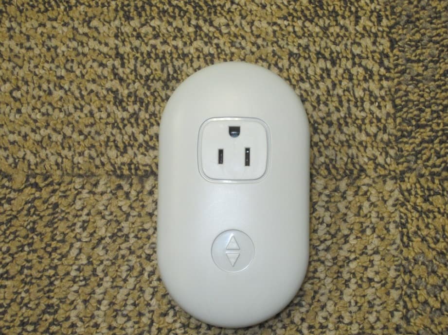
LPM-10000
May 20, 2015Smart Outlet
Equipment Class
DTS - Digital Transmission System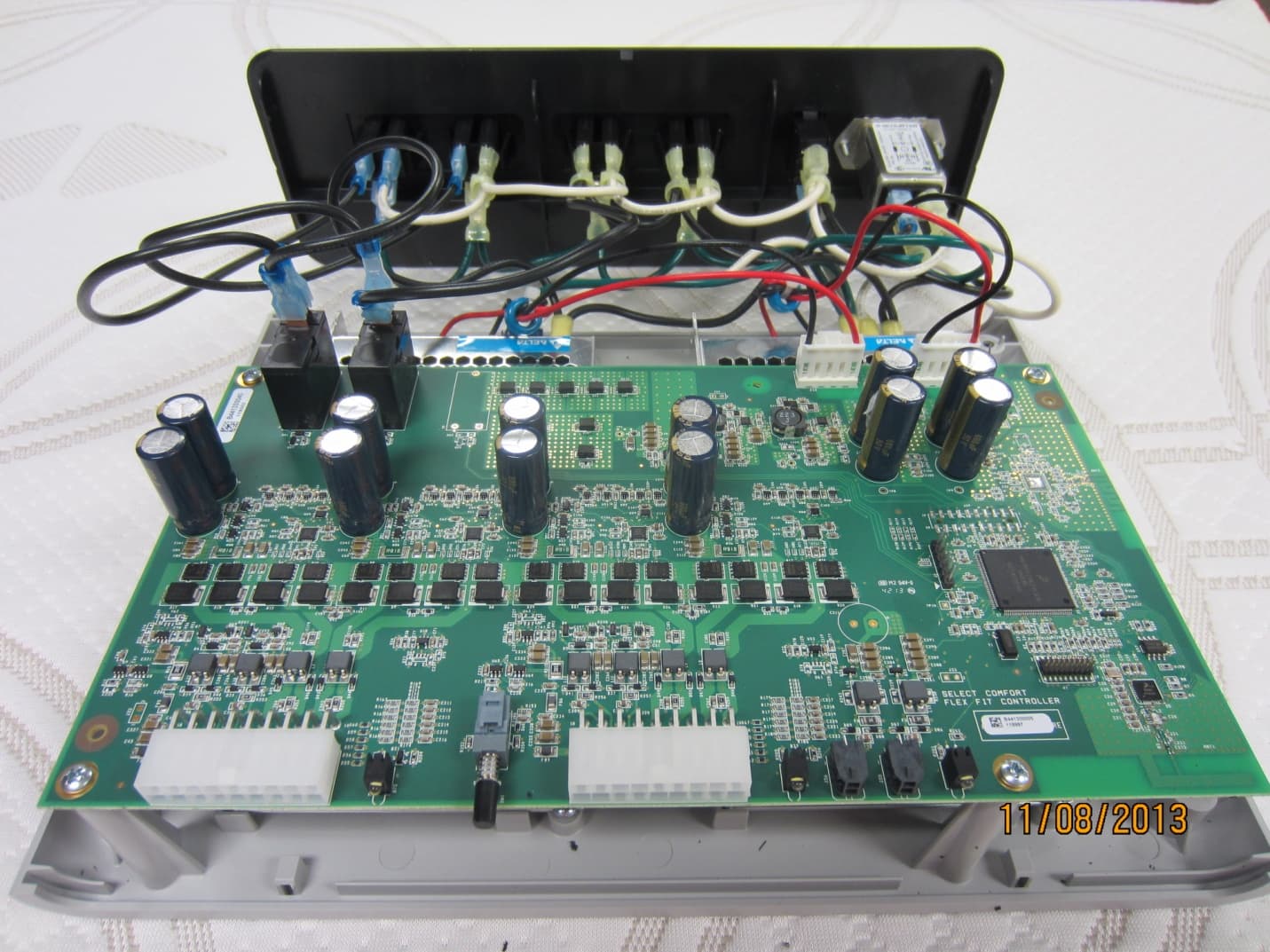
LPM-9000A
Dec 01, 2013Select Comfort Flex Fit
Equipment Class
DTS - Digital Transmission SystemLPM-6000A
Mar 21, 2013Dual Temperature Engine
Equipment Class
DXX - Part 15 Low Power Communication Device Transmitter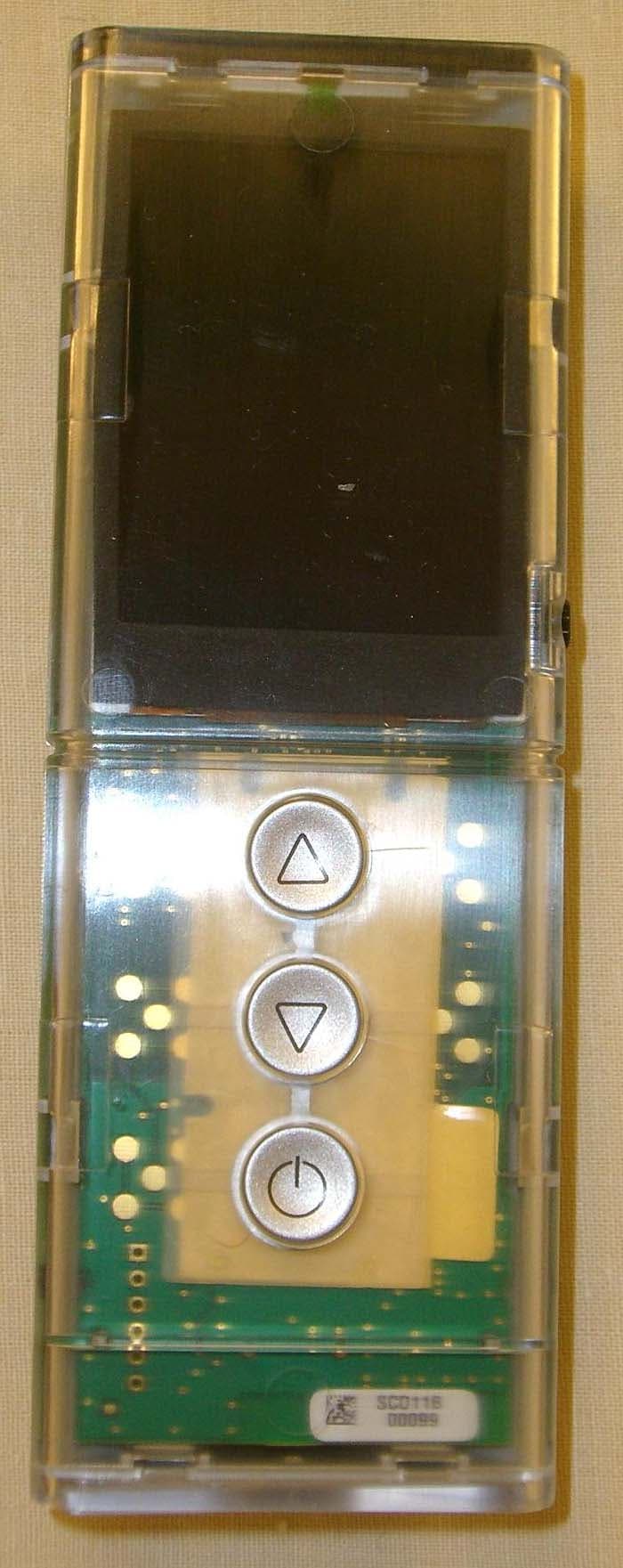
LPM-5000A
Mar 10, 2013NXT Remote
Equipment Class
DXX - Part 15 Low Power Communication Device Transmitter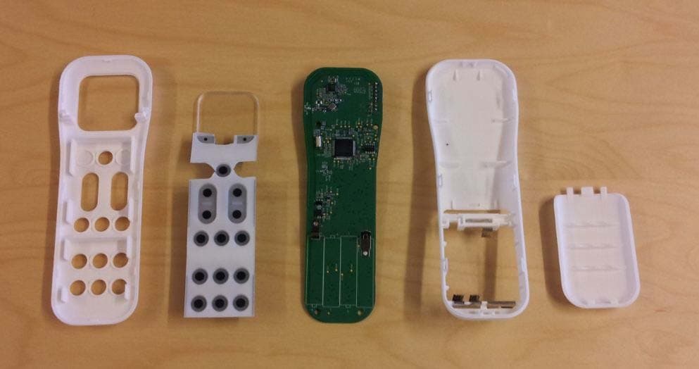
LPM-1000G
Jun 05, 2012Adjustable Foundation Remote
Equipment Class
DSC - Part 15 Security/Remote Control Transmitter