LPM-6000ADual Temperature Engine
Sleep Number CorporationApplication Details
- Equipment Class
- DXX - Part 15 Low Power Communication Device Transmitter
- Date of Grant
- Mar 21, 2013
- Application Purpose
- Original Equipment
- Date of Application
- Mar 21, 2013
- Equipment Note
- Dual Temperature Engine
- Frequency Range
- 2405.00000000 - 2480.00000000
- Company
- Sleep Number Corporation
- Country
- United States
Documents & Files
Document Text
Text extracted from the exhibit documents filed with the FCC. Open a document above to read the original.
Users Manual
TEMPERATURE bAlAncing lAyER insTRUcTion MAnUAl Dual Temp SM if you ever have product questions or need additional assistance obtaining optimal comfort, please visit us at sleepnumber.com or call 1.800.472.7185 Representatives are available: (central standard Time): Monday–Friday 8 a.m. – 6 p.m. saturday 8:30 a.m. – 5 p.m. sunday closed connect with us on Facebook and Twitter Facebook.com/sleepnumber beds.com/Twitter Help is just a click or phone call away. ® click to see DualTemp ™ in action FPO 2:00 2:00 Sara TEMPERATURE bAlAncing lAyER insTRUcTion MAnUAl Dual Temp SM if you ever have product questions or need additional assistance obtaining optimal comfort, please visit us at sleepnumber.com or call 1.800.472.7185 Representatives are available: (central standard Time): Monday–Friday 8 a.m. – 6 p.m. saturday 8:30 a.m. – 5 p.m. sunday closed connect with us on Facebook and Twitter Facebook.com/sleepnumber beds.com/Twitter Help is just a click or phone call away. 2:00 2:00 Sara 56 The DualTemp ™ system features an extraordinary comfort layer that can be added to any bed and an innovative cooling and heating source. it allows you to select your ideal temperature on each side at the simple touch of a button. so you both can achieve a balanced, blissful night’s sleep. DualTemp ™ comfort layer (1) Heating and cooling source (2) Remote (2) batteries included Power supply (2) Power cord (2) DualTemp ™ layer it’s a new degree of sleep. What’s inside. Assembly Follow these 6 simple steps to correctly assemble your DualTemp ™ comfort layer. Place the DualTemp ™ comfort layer on the bed with the lighter side facing up. 1 Place the heating and cooling source on the floor next to your bed or underneath it on a level surface. 2 insert batteries in the remote and press the button to bind the remote to the heating and cooling source. 2:00 Sara 6 connect the power supply to the heating and cooling source and to the power cord. Plug the power cord into an outlet or surge protector. 3 Plug the power supply into the first heating and cooling source. 4 Attach the connector to the heating and cooling source by aligning the notch on the connector to the silver ball on the heating and cooling source. Push together until you hear a click. 5 Repeat steps 2–6 on the other side of the DualTemp ™ comfort layer with the second heating and cooling source and it’s remote. Remote Function Use the up/down buttons to control the warming/ cooling levels Cooling levels lowmediumhigh 2:00 Heating levelsFan lowmediumhigh After installing batteries, press the button and follow the on-screen instructions to set up your remotes. 2:00 Sara There are three levels of cooling, with the fan speed increasing as the setting gets cooler. The cool air circulates underneath you to keep you sleeping cool and comfortably, so you won’t wake up hot. blows room-temperature air underneath you for extra breathability; it may feel cool. There are three levels of heating, with the fan speed increasing as the setting gets warmer. The warm air circulates underneath you to keep you comfy and cozy with a warm sleeping environment. Optimize DualTemp ™ comfort layer performance • To maximize thermal comfort, it is recommended to turn on the DualTemp ™ comfort layer 20 minutes prior to going to bed. Keep the layer covered with a blanket/comforter/quilt to maintain the desired temperature. • The DualTemp ™ comfort layer is meant to be used on top of your mattress/mattress pad and underneath a fitted sheet only. For best results, place a blanket/comforter/quilt on top of the bed to create a comfortable micro-climate. • Do not place a mattress pad on top of the DualTemp ™ comfort layer. Doing so will greatly reduce the performance of the system. • Use sheets made from a breathable material that will allow the air to flow through. Flannel and micro-fleece sheets are not recommended; they will reduce the airflow and the effectiveness of the system. • Optional: For more airflow to the foot of the bed, or to reduce the level of white noise created from air blowing in the DualTemp ™ comfort layer, you may place the layer on the bed with the connectors at the foot of the bed. be sure the lighter gray side of the comfort layer is facing up. • If you often wake up too warm or too cold, it is recommended to set the timer for your DualTemp ™ system to turn off after 3-5 hours. Optimize heating and cooling source performance • System air temperature is dependent on the room temperature. in a cool room, the settings will be cooler, than in a warmer room. • The DualTemp ™ system is not a replacement for air-conditioning or heating your home. • If you have a bed skirt and want to optimize the comfort layer’s thermal performance you may need to place the heating and cooling source next to the bed vs. underneath, or consider removing your bed skirt. • If you store items under your bed, ensure you have a 1 foot open perimeter around the heating and cooling source. • The filters on the heating and cooling source should be cleaned or replaced every 6 months. They may be washed and reused or additional filters may be purchased from sleep number. see page 13 for instructions on cleaning/ replacing filters. noTE: When using the cooling mode in a high humidity environment, water can collect in the bottom of the heating and cooling source. The water will automatically be removed during the refreshing system cycle. Do not unplug and avoid moving the heating and cooling source until the cycle is complete. Warnings • The Dual Temp ™ system is not to be used with an adjustable base. • The connector at the head of the bed should not be pinched between the bed and any other object, as this will degrade system performance. DualTemp ™ system operation Using the Timer The timer may be set to turn off the DualTemp ™ system after a specified length of time. The timer can be set for 1–9 hours. To set the timer, press the button on the side of the remote. Then press the up arrow on the front o…
Text truncated - open the document above for the full version.
Cover Letter(s)
WTD 12.7.3 FCC Compliance Opinion SECF0012 Information about the Applicant Grantee (Company Name) Select Comfort Corporation FCC Contact Person Jeffrey Barnum Address 9800 59th Avenue North City, State, Zip Minneapolis, MN 55442 Job Number SECF0012 Model Dual Temperature Engine FCC ID LPM-6000A Agent Approval Type Original Equipment Class DXX Part 15, Low Power Communication Device Transmitter Rule Part 15.249 Overview The Dual Temperature Engine is controlled by a wireless remote and used to heat/cool bed panels. The device operates between 2.405 and 2.480 GHz. Confidentiality requested for allowed files. Request is properly addressed and referenced. Recommendation All items have been resolved and completed to my satisfaction; therefore I recommend this application for approval. Signature Dave Tolman, TCB Committee 3/21/2013
Operational Description
To Whom It May Concern: The antenna for Model Number PCE-302-00-0 is a board etched Omni-directional inverted F – antenna with a gain of approximately 1 dBi. Document Number: ZHDCRM Rev. 1.4 04/2011 Freescale IEEE 802.15.4 / ZigBee Package and Hardware Layout Considerations Reference Manual How to Reach Us: Home Page: www.freescale.com E-mail: [email protected] USA/Europe or Locations Not Listed: Freescale Semiconductor Technical Information Center, CH370 1300 N. Alma School Road Chandler, Arizona 85224 +1-800-521-6274 or +1-480-768-2130 [email protected] Europe, Middle East, and Africa: Freescale Halbleiter Deutschland GmbH Technical Information Center Schatzbogen 7 81829 Muenchen, Germany +44 1296 380 456 (English) +46 8 52200080 (English) +49 89 92103 559 (German) +33 1 69 35 48 48 (French) [email protected] Japan: Freescale Semiconductor Japan Ltd. Headquarters ARCO Tower 15F 1-8-1, Shimo-Meguro, Meguro-ku, Tokyo 153-0064, Japan 0120 191014 or +81 3 5437 9125 [email protected] Asia/Pacific: Freescale Semiconductor Hong Kong Ltd. Technical Information Center 2 Dai King Street Tai Po Industrial Estate Tai Po, N.T., Hong Kong +800 2666 8080 [email protected] For Literature Requests Only: Freescale Semiconductor Literature Distribution Center P.O. Box 5405 Denver, Colorado 80217 1-800-521-6274 or 303-675-2140 Fax: 303-675-2150 [email protected] Information in this document is provided solely to enable system and software implementers to use Freescale Semiconductor products. There are no express or implied copyright licenses granted hereunder to design or fabricate any integrated circuits or integrated circuits based on the information in this document. Freescale Semiconductor reserves the right to make changes without further notice to any products herein. Freescale Semiconductor makes no warranty, representation or guarantee regarding the suitability of its products for any particular purpose, nor does Freescale Semiconductor assume any liability arising out of the application or use of any product or circuit, and specifically disclaims any and all liability, including without limitation consequential or incidental damages. “Typical” parameters that may be provided in Freescale Semiconductor data sheets and/or specifications can and do vary in different applications and actual performance may vary over time. All operating parameters, including “Typicals”, must be validated for each customer application by customer’s technical experts. Freescale Semiconductor does not convey any license under its patent rights nor the rights of others. Freescale Semiconductor products are not designed, intended, or authorized for use as components in systems intended for surgical implant into the body, or other applications intended to support or sustain life, or for any other application in which the failure of the Freescale Semiconductor product could create a situation where personal injury or death may occur. Should Buyer purchase or use Freescale Semiconductor products for any such unintended or unauthorized application, Buyer shall indemnify and hold Freescale Semiconductor and its officers, employees, subsidiaries, affiliates, and distributors harmless against all claims, costs, damages, and expenses, and reasonable attorney fees arising out of, directly or indirectly, any claim of personal injury or death associated with such unintended or unauthorized use, even if such claim alleges that Freescale Semiconductor was negligent regarding the design or manufacture of the part. Introduction to Choosing MLC Capacitors For Bypass/Decoupling Applications, © AVX Corporation. Via Inductance II High-speed Digital Design, HIGH-SPEED DIGITAL DESIGN -online newsletter- Vol. 6 Issue 8, © 1993-2007 Signal Consulting, Inc. Chip Monolithic Ceramic Capacitors, © Murata Manufacturing Company, Ltd Freescale and the Freescale logo are trademarks or registered trademarks of Freescale Semiconductor, Inc. in the U.S. and other countries. All other product or service names are the property of their respective owners. ARM is the registered trademark of ARM Limited. ARM7TDMI-S is the trademark of ARM Limited.© Freescale Semiconductor, Inc. 2008, 2009, 2010, 2011 802.15.4/ZigBee Hardware Design Considerations Reference Manual, Rev. 1.4 Freescale Semiconductori Contents About This Book Audience . . . . . . . . . . . . . . . . . . . . . . . . . . . . . . . . . . . . . . . . . . . . . . . . . . . . . . . . . . . . . . . . . . . . iii Organization . . . . . . . . . . . . . . . . . . . . . . . . . . . . . . . . . . . . . . . . . . . . . . . . . . . . . . . . . . . . . . . . . iii Revision History . . . . . . . . . . . . . . . . . . . . . . . . . . . . . . . . . . . . . . . . . . . . . . . . . . . . . . . . . . . . . . iii Recommended Reading . . . . . . . . . . . . . . . . . . . . . . . . . . . . . . . . . . . . . . . . . . . . . . . . . . . . . . . . . v Chapter 1 Introduction 1.132-Contact Quad Flat Pack No Lead (QFN32) . . . . . . . . . . . . . . . . . . . . . . . . . . . . . . . . . . . . . 1-1 1.271-Contact Land Grid Array (LGA) . . . . . . . . . . . . . . . . . . . . . . . . . . . . . . . . . . . . . . . . . . . . . . 1-2 1.399-Contact Land Grid Array (LGA) . . . . . . . . . . . . . . . . . . . . . . . . . . . . . . . . . . . . . . . . . . . . . . 1-2 1.4Layout and RF Design Considerations . . . . . . . . . . . . . . . . . . . . . . . . . . . . . . . . . . . . . . . . . . . . 1-3 Chapter 2 QFN Packaging Information 2.1QFN Component Copper Layer . . . . . . . . . . . . . . . . . . . . . . . . . . . . . . . . . . . . . . . . . . . . . . . . . 2-1 2.2QFN Solder Mask . . . . . . . . . . . . . . . . . . . . . . . . . . . . . . . . . . . . . . . . . . . . . . . . . . . . . . . . . . . . 2-3 2.2.1QFN Solder Paste Stencil . . . . . . . . . . . . . . . . . . . . . . . . . . . . . . . . . . . . . . . . . . . . . . . . . . . 2-4 2.2.2QFN Problems with Excess Solder. . . . . .…
Text truncated - open the document above for the full version.
Test Setup Photos
photo EV01 SRB 03-07-13 009.JPG EV01 SRB 03-07-13 001.JPG Field Strength of Fundamental PSA-ESCI 2012.12.14 photo EV01 SRB 03-07-13 002.JPG EV01 SRB 03-07-13 003.JPG Field Strength of Fundamental PSA-ESCI 2012.12.14 photo EV01 SRB 03-07-13 004.JPG Field Strength of Fundamental PSA-ESCI 2012.12.14 Duty Cycle XMit 2012.09.20 NORTHWEST Duty Cycle PsaTx 2013.01.10 EMC EV09 temp chamber 001.JPG EV09 temp chamber 002.JPG Duty Cycle photo EV01 SRB 03-07-13 009.JPG EV01 SRB 03-07-13 001.JPG Field Strength of Harmonics and Spurious Radiated Emissions PSA-ESCI 2012.12.14 photo EV01 SRB 03-07-13 002.JPG EV01 SRB 03-07-13 003.JPG Field Strength of Harmonics and Spurious Radiated Emissions PSA-ESCI 2012.12.14 photo EV01 SRB 03-07-13 004.JPG Field Strength of Harmonics and Spurious Radiated Emissions PSA-ESCI 2012.12.14 photo CE and RE 03-07-13 006.JPG CE and RE 03-07-13 004.JPG AC Powerline Conducted Emissions PSA-ESCI 2012.12.14 photo CE and RE 03-07-13 005.JPG AC Powerline Conducted Emissions PSA-ESCI 2012.12.14
Contact Information
Applicant
Jeff Barnum(VP of Manufacturing Operations)
Test Firm
Northwest EMC, Inc.Greg Kiemel
Technical Specifications
| # | Rule Parts | Frequency Range | Power Output |
|---|---|---|---|
| 1 | 15C | 2.40 GHz - 2.48 GHz | - |
Other Applications from Sleep Number Corporation
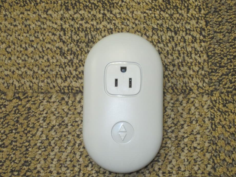
LPM-10000
May 20, 2015Smart Outlet
Equipment Class
DTS - Digital Transmission System
LPM-7000A
Feb 23, 2014Sleep monitoring and tracking system with the ability to monitor heart rate, respiration rate, and motion.
Equipment Class
DTS - Digital Transmission System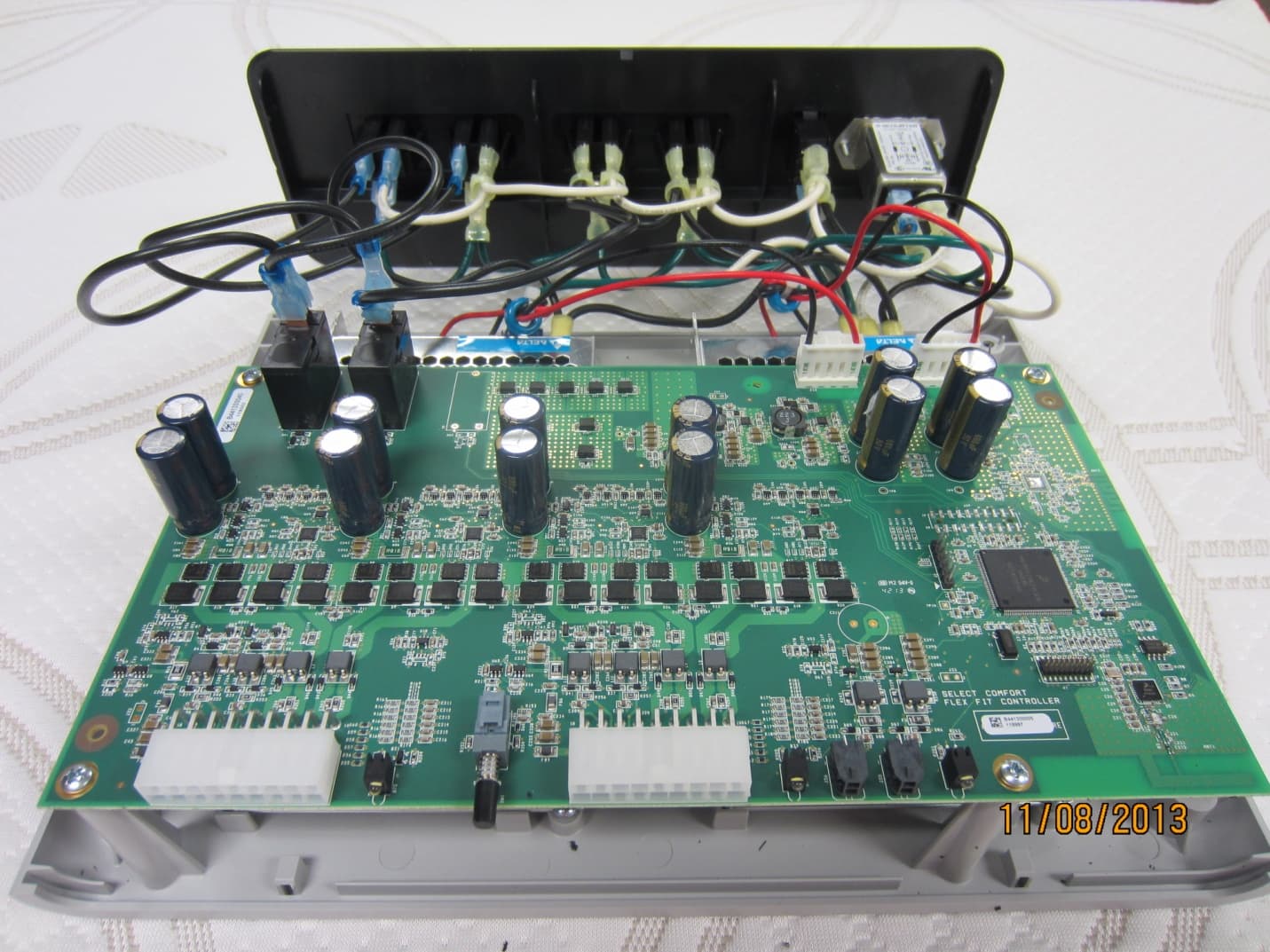
LPM-9000A
Dec 01, 2013Select Comfort Flex Fit
Equipment Class
DTS - Digital Transmission System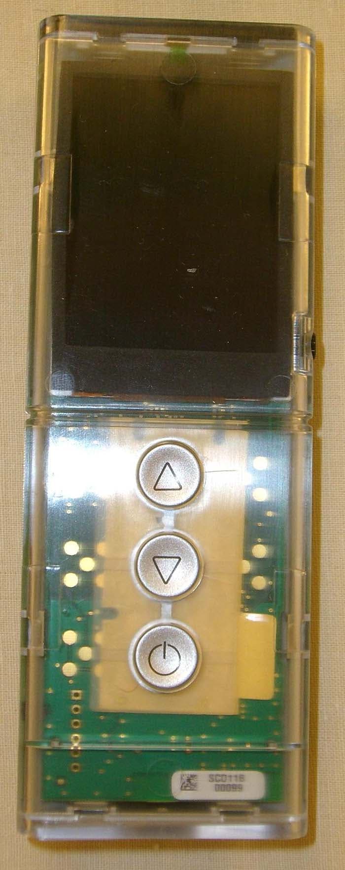
LPM-5000A
Mar 10, 2013NXT Remote
Equipment Class
DXX - Part 15 Low Power Communication Device Transmitter
LPM-1000G
Jun 05, 2012Adjustable Foundation Remote
Equipment Class
DSC - Part 15 Security/Remote Control Transmitter