LPM-5000ANXT Remote
Sleep Number Corporation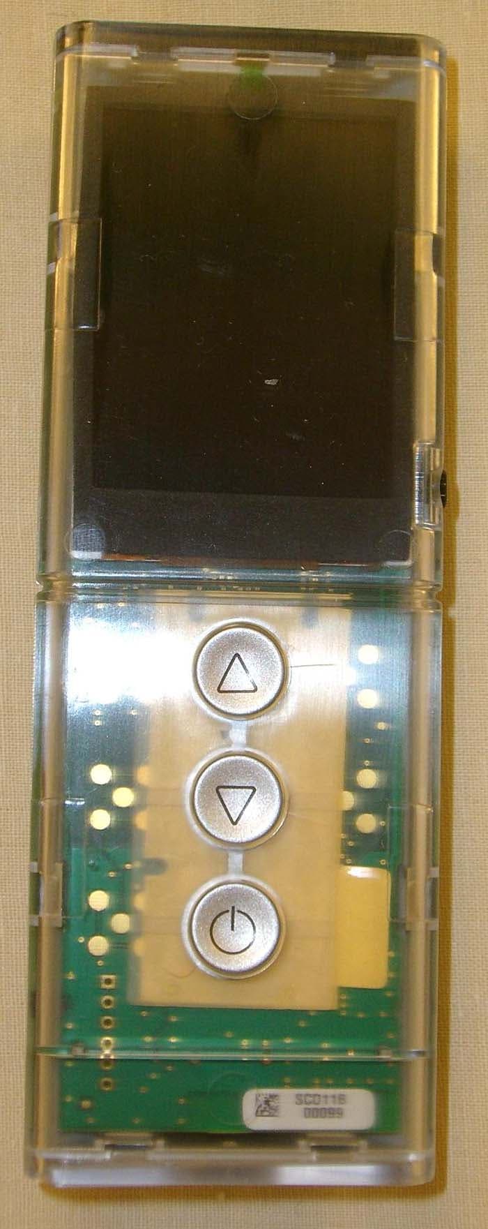
Click to zoom
Application Details
- Equipment Class
- DXX - Part 15 Low Power Communication Device Transmitter
- Date of Grant
- Mar 10, 2013
- Application Purpose
- Original Equipment
- Date of Application
- Mar 10, 2013
- Equipment Note
- NXT Remote
- Frequency Range
- 2405.00000000 - 2480.00000000
- Company
- Sleep Number Corporation
- Country
- United States
Documents & Files
Document Text
Text extracted from the exhibit documents filed with the FCC. Open a document above to read the original.
Users Manual
TEMPERATURE bAlAncing lAyER insTRUcTion MAnUAl Dual Temp SM if you ever have product questions or need additional assistance obtaining optimal comfort, please visit us at sleepnumber.com or call 1.800.472.7185 Representatives are available: (central standard Time): Monday–Friday 8 a.m. – 6 p.m. saturday 8:30 a.m. – 5 p.m. sunday closed connect with us on Facebook and Twitter Facebook.com/sleepnumber beds.com/Twitter Help is just a click or phone call away. ® click to see DualTemp ™ in action FPO 2:00 2:00 Sara TEMPERATURE bAlAncing lAyER insTRUcTion MAnUAl Dual Temp SM if you ever have product questions or need additional assistance obtaining optimal comfort, please visit us at sleepnumber.com or call 1.800.472.7185 Representatives are available: (central standard Time): Monday–Friday 8 a.m. – 6 p.m. saturday 8:30 a.m. – 5 p.m. sunday closed connect with us on Facebook and Twitter Facebook.com/sleepnumber beds.com/Twitter Help is just a click or phone call away. 2:00 2:00 Sara 56 The DualTemp ™ system features an extraordinary comfort layer that can be added to any bed and an innovative cooling and heating source. it allows you to select your ideal temperature on each side at the simple touch of a button. so you both can achieve a balanced, blissful night’s sleep. DualTemp ™ comfort layer (1) Heating and cooling source (2) Remote (2) batteries included Power supply (2) Power cord (2) DualTemp ™ layer it’s a new degree of sleep. What’s inside. Assembly Follow these 6 simple steps to correctly assemble your DualTemp ™ comfort layer. Place the DualTemp ™ comfort layer on the bed with the lighter side facing up. 1 Place the heating and cooling source on the floor next to your bed or underneath it on a level surface. 2 insert batteries in the remote and press the button to bind the remote to the heating and cooling source. 2:00 Sara 6 connect the power supply to the heating and cooling source and to the power cord. Plug the power cord into an outlet or surge protector. 3 Plug the power supply into the first heating and cooling source. 4 Attach the connector to the heating and cooling source by aligning the notch on the connector to the silver ball on the heating and cooling source. Push together until you hear a click. 5 Repeat steps 2–6 on the other side of the DualTemp ™ comfort layer with the second heating and cooling source and it’s remote. Remote Function Use the up/down buttons to control the warming/ cooling levels Cooling levels lowmediumhigh 2:00 Heating levelsFan lowmediumhigh After installing batteries, press the button and follow the on-screen instructions to set up your remotes. 2:00 Sara There are three levels of cooling, with the fan speed increasing as the setting gets cooler. The cool air circulates underneath you to keep you sleeping cool and comfortably, so you won’t wake up hot. blows room-temperature air underneath you for extra breathability; it may feel cool. There are three levels of heating, with the fan speed increasing as the setting gets warmer. The warm air circulates underneath you to keep you comfy and cozy with a warm sleeping environment. Optimize DualTemp ™ comfort layer performance • To maximize thermal comfort, it is recommended to turn on the DualTemp ™ comfort layer 20 minutes prior to going to bed. Keep the layer covered with a blanket/comforter/quilt to maintain the desired temperature. • The DualTemp ™ comfort layer is meant to be used on top of your mattress/mattress pad and underneath a fitted sheet only. For best results, place a blanket/comforter/quilt on top of the bed to create a comfortable micro-climate. • Do not place a mattress pad on top of the DualTemp ™ comfort layer. Doing so will greatly reduce the performance of the system. • Use sheets made from a breathable material that will allow the air to flow through. Flannel and micro-fleece sheets are not recommended; they will reduce the airflow and the effectiveness of the system. • Optional: For more airflow to the foot of the bed, or to reduce the level of white noise created from air blowing in the DualTemp ™ comfort layer, you may place the layer on the bed with the connectors at the foot of the bed. be sure the lighter gray side of the comfort layer is facing up. • If you often wake up too warm or too cold, it is recommended to set the timer for your DualTemp ™ system to turn off after 3-5 hours. Optimize heating and cooling source performance • System air temperature is dependent on the room temperature. in a cool room, the settings will be cooler, than in a warmer room. • The DualTemp ™ system is not a replacement for air-conditioning or heating your home. • If you have a bed skirt and want to optimize the comfort layer’s thermal performance you may need to place the heating and cooling source next to the bed vs. underneath, or consider removing your bed skirt. • If you store items under your bed, ensure you have a 1 foot open perimeter around the heating and cooling source. • The filters on the heating and cooling source should be cleaned or replaced every 6 months. They may be washed and reused or additional filters may be purchased from sleep number. see page 13 for instructions on cleaning/ replacing filters. noTE: When using the cooling mode in a high humidity environment, water can collect in the bottom of the heating and cooling source. The water will automatically be removed during the refreshing system cycle. Do not unplug and avoid moving the heating and cooling source until the cycle is complete. Warnings • The Dual Temp ™ system is not to be used with an adjustable base. • The connector at the head of the bed should not be pinched between the bed and any other object, as this will degrade system performance. DualTemp ™ system operation Using the Timer The timer may be set to turn off the DualTemp ™ system after a specified length of time. The timer can be set for 1–9 hours. To set the timer, press the button on the side of the remote. Then press the up arrow on the front o…
Text truncated - open the document above for the full version.
Cover Letter(s)
WTD 12.7.3 FCC Compliance Opinion SECF0009 Information about the Applicant Grantee (Company Name) Select Comfort Corporation FCC Contact Person Jeffrey Barnum Address 9800 59th Avenue North City, State, Zip Minneapolis, MN 55442 Job Number SECF0009 Model NXT Remote FCC ID LPM-5000A Agent Approval Type Original Equipment Class DXX – Part 15 Low Power Communication Device Transmitter Rule Part 15.249 Overview The NXT Remote is used to control the temperature settings of heated/cooled bed panels. Confidentiality requested for allowed files. Request is properly addressed and referenced. Recommendation All items have been resolved and completed to my satisfaction; therefore I recommend this application for approval. Signature Dave Tolman, TCB Committee 3/8/2013
External Photos
FCC Exhibit – External Photos Company: Select Comfort FCC ID: LPM-5000A Figure 1 - Assembly Components Front View Figure 2 - Assembly Components Rear View Figure 3 - Assembled Remote Front View Figure 4 - Assembled Remote Rear View Figure 5 - Assembled Remote Left View Figure 6 - Assembled Remote Right View Figure 7 - Assembled Remote Top View Figure 8 - Assembled Remote Bottom View
ID Label/Location Info
FCC Exhibit – FCC Image Location Company: Select Comfort FCC ID: LPM-5000A Figure 1 - Assembled Remote Rear View; FCC ID will be located in the battery compartment; see Figure 2 Figure 2 - Detail from case drawing showing location where FCC ID will be molded into the battery compartment.
Internal Photos
FCC Exhibit – Internal Photos Company: Select Comfort FCC ID: LPM-5000A Figure 1 – Rear Side of Circuit Board Figure 2 Front Side of Circuit Board Figure 3 - Detail of antenna and radio on rear side of board. Radio Antenna
Operational Description
Application Note AN043 Small Size 2.4 GHz PCB antenna By Audun Andersen 1 KEYWORDS • CC25xx • CC24xx • CC2480 • PCB antenna • USB dongle • 2.4 GHz • Inverted F Antenna 2 INTRODUCTION The PCB antenna used on the CC2511 USB dongle reference design is described in this application note. Even if the antenna presented is for a USB dongle design it can be used in all 2.4 GHz designs, especially where small space is required for the antenna. This application note describes the antenna dimensions, the RF performance and considerations for complying with regulatory limits when using this design. The suggested antenna design requires no more than 15.2 x 5.7 mm of space and ensures a VSWR ratio of less than 2 across the 2.4 GHz ISM band when connected to a 50 ohm source. Figure 1: CC2511 USB Dongle SWRA117D Page 1 of 21 Application Note AN043 Table of Contents 1 KEYWORDS...................................................................................................................1 2 INTRODUCTION.............................................................................................................1 3 ABBREVIATIONS...........................................................................................................2 4 ANTENNA DESIGN........................................................................................................3 4.1 DESIGN GOALS..........................................................................................................3 4.2 SIMULATION...............................................................................................................3 4.3 LAYOUT AND IMPLEMENTATION...................................................................................4 5 TEST RESULTS.............................................................................................................5 5.1 REFLECTION..............................................................................................................5 5.2 RADIATION PATTERN..................................................................................................7 5.3 OUTPUT POWER......................................................................................................15 5.4 SPURIOUS EMISSION AND HARMONICS......................................................................17 6 CONCLUSION ..............................................................................................................20 7 GENERAL INFORMATION..........................................................................................21 7.1 DOCUMENT HISTORY................................................................................................21 3 ABBREVIATIONS CAD Computer Aided Design CC24xx CC2400, CC2420, CC2430 and CC2431 CC25xx CC2500, CC2510, CC2511, CC2550 and CC2520 CC2480 Z-Accel ZigBee Processor IFA Inverted F Antenna ISM Industrial, Scientific and Medical LOS Line Of Sight PCB Printed Circuit Board PER Packet Error Rate VSWR Voltage Standing Wave Ratio SWRA117D Page 2 of 21 Application Note AN043 4 ANTENNA DESIGN The PCB antenna on the CC2511 USB dongle reference design is a meandered Inverted F Antenna (IFA). The IFA was designed to match an impedance of 50 ohm at 2.45 GHz. Thus no additional matching components are necessary. 4.1 Design Goals The reflection at the feed point of the antenna determines how much of the applied power is delivered to the antenna. A reflection of less than -10 dB across the 2.4 GHz ISM band, when connected to a 50 ohm source, was a design goal. Reflection of less than -10 dB, or VSWR less than 2, ensures that more than 90% of the available power is delivered to the antenna. Bandwidth is in this document defined as the frequency band where more than 90% of the available power is delivered to the antenna. Another design goal was to fit the size of the PCB antenna on a USB dongle and to obtain good performance also when the dongle is connected to a computer. 4.2 Simulation IE3D from Zeland, which is an electromagnetic simulation tool, was used to design the antenna. The accuracy of the simulation is controlled by the mesh. An increase of the mesh increases the simulation time. Thus, for initial simulations mesh = 1 should be used. When a fairly good result is achieved a higher mesh should be used to obtain more accurate results. Comparison of simulation and measurement results shows that the measured reflection is between the result obtained with mesh = 5 and mesh = 1; see Figure 2 for details. Figure 2: Comparison of Simulation and Measurements Results SWRA117D Page 3 of 21 Application Note AN043 4.3 Layout and Implementation Small changes of the antenna dimensions may have large impact on the performance. Therefore it is strongly recommended to make an exact copy of the reference design to achieve optimum performance. The easiest way to implement the antenna is to import the gerber or DXF file showing the antenna layout. These files are named IFA_USB.spl and IFA_USB.dxf respectively and are included in the CC2511 USB dongle reference design available from http://www.ti.com\lpw. The imported file can be used as a template when drawing the antenna. By using this procedure it should be possible to make an exact copy. If the PCB CAD tool being used does not support import of DXF or gerber files, Figure 3 and Table 1 should be used to ensure correct implementation. It is recommended to generate a gerber file for comparison with IFA_USB.spl when making a manual implementation. Most gerber viewers have the possibility to import several gerber files at the same time. Thus by placing the gerber file, showing the manually implemented antenna, on top of IFA_USB.spl it is easy to verify that the antenna is correctly implemented. It is also recommended to use the same thickness and type of PCB material as used in the reference design. Information about the PCB can be found in a separate readme file included in the reference design. To compensate for a thicker/thinner P…
Text truncated - open the document above for the full version.
Test Report
Select Comfort Corporation NXT Remote FCC 15.249:2013 Report #: SECF0009 Report Prepared By Northwest EMC Inc. NORTHWEST EMC – (888) 364-2378 – www.nwemc.com California – Minnesota – Oregon – New York – Washington WTD 12.5.23 CERTIFICATE OF TEST Last Date of Test: February 18, 2013 Select Comfort Corporation Model: NXT Remote Emissions Test Description Specification Test Method Pass/Fail Field Strength of Fundamental FCC 15.249:2013 ANSI C63.10:2009 Pass Field Strength of Harmonics and Spurious Radiated Emissions FCC 15.249:2013 ANSI C63.10:2009 Pass Deviations From Test Standards None Approved By: Don Facteau, IS Manager NVLAP Lab Code: 200881-0 Test Facility The measurement facility used to collect the data is located at: Northwest EMC, Inc. 9349 W Broadway Ave. Brooklyn Park, MN 55445 Phone: (763) 425-2281 Fax: (763) 424-3469 This site has been fully described in a report filed with and accepted by the FCC (Federal Communications Commission) and Industry Canada (Site filing #2834E-1). This report must not be used to claim product certification, approval, or endorsement by NVLAP, NIST, or any agency of the federal government of the United States of America. Product compliance is the responsibility of the client, therefore the tests and equipment modes of operation represented in this report were agreed upon by the client, prior to testing. This Report may only be duplicated in its entirety. The results of this test pertain only to the sample(s) tested. The specific description is noted in each of the individual sections of the test report supporting this certificate of test. REV 2012.08.02 REVISION HISTORY Revision Number Description Date Page Number 00 None Barometric Pressure The recorded barometric pressure has been normalized to sea level. REV 2012.05.24 ACCREDITATIONS AND AUTHORIZATIONS United States FCC - Designated by the FCC as a Telecommunications Certification Body (TCB). Certification chambers, Open Area Test Sites, and conducted measurement facilities are listed with the FCC. A2LA - Accredited by A2LA to ISO / IEC Guide 65 as a product certifier. This allows Northwest EMC to certify transmitters to FCC and IC specifications. NVLAP - Each laboratory is accredited by NVLAP to ISO 17025 Canada IC - Recognized by Industry Canada as a Certification Body (CB). Certification chambers and Open Area Test Sites are filed with IC. European Union European Commission – Validated by the European Commission as a Conformity Assessment Body (CAB) under the EMC directive and as a Notified Body under the R&TTE Directive. Australia/New Zealand ACMA - Recognized by ACMA as a CAB for the acceptance of test data. Korea KCC / RRA - Recognized by KCC’s RRA as a CAB for the acceptance of test data. Japan VCCI - Associate Member of the VCCI. Conducted and radiated measurement facilities are registered. Taiwan BSMI – Recognized by BSMI as a CAB for the acceptance of test data. NCC - Recognized by NCC as a CAB for the acceptance of test data. Singapore IDA – Recognized by IDA as a CAB for the acceptance of test data. Hong Kong OFTA – Recognized by OFTA as a CAB for the acceptance of test data. Vietnam MIC – Recognized by MIC as a CAB for the acceptance of test data. Russia GOST – Accredited by Certinform VNIINMASH, CERTINFO, SAMTES, and Federal CHEC to perform EMC and Hygienic testing for Information Technology products to GOST standards. SCOPE For details on the Scopes of our Accreditations, please visit: http://www.nwemc.com/accreditations/ REV 2012.08.02 MEASUREMENT UNCERTAINTY Measurement Uncertainty When a measurement is made, the result will be different from the true or theoretically correct value. The difference is the result of tolerances in the measurement system that cannot be completely eliminated. To the extent that technology allows us, it has been our aim to minimize this error. Measurement uncertainty is a statistical expression of measurement error qualified by a probability distribution. A measurement uncertainty estimation has been performed for each test per our internal quality document WP 342. The estimation is used to compare the measured result with its "true" or theoretically correct value. The expanded measurement uncertainty (K=2) for each test is on each data sheet. Our measurement data meets or exceeds the measurement uncertainty requirements of the applicable specification; therefore, the test data can be compared directly to the specification limit to determine compliance. The calculations for estimating measurement uncertainty are based upon ETSI TR 100 028 (or CISPR 16-4-1 as applicable), and are available upon request. The following table represents the Measurement Uncertainty (MU) budgets for each of the tests that may be contained in this report. Test + MU - MU Frequency Accuracy (Hz) 0.12 -0.01 Amplitude Accuracy (dB) 0.49 -0.49 Conducted Power (dB) 0.41 -0.41 Radiated Power via Substitution (dB) 0.69 -0.68 Temperature (degrees C) 0.81 -0.81 Humidity (% RH) 2.89 -2.89 Field Strength (dB) 3.80 -3.80 AC Powerline Conducted Emissions (dB) 2.94 -2.94 REV 2013.01.07 LOCATIONS Oregon Labs EV01-12 22975 NW Evergreen Pkwy Hillsboro, OR 97124 (503) 844-4066 California Labs OC01-13 41 Tesla Irvine, CA 92618 (949) 861-8918 New York Labs WA01-04 4939 Jordan Rd. Elbridge, NY 13060 (315) 685-0796 Minnesota Labs MN01-08 9349 W Broadway Ave. Brooklyn Park, MN 55445 (763) 425-2281 Washington Labs NC01-05,SU02,SU07 19201 120 th Ave. NE Bothell, WA 98011 (425) 984-6600 VCCI A-0108 A-0029 A-0109 A-0110 Industry Canada 2834D-1, 2834D-2 2834B-1, 2834B-2, 2834B-3 2834E-1 2834C-1 WTD 12.5.23 PRODUCT DESCRIPTION Client and Equipment Under Test (EUT) Information Company Name: Select Comfort Corporation Address: 9800 59th Avenue North City, State, Zip: Minneapolis, MN 55442 Test Requested By: Maxine Chen Model: NXT Remote First Date of Test: February 18, 2013 Last Date of Test: February 18, 2013 Receipt Date of Samples: February 18, 2013 Equipment Design Stage: Prototype Equipment Condition: …
Text truncated - open the document above for the full version.
Test Setup Photos
photo FF 001.JPG FF 002.JPG Field Strength of Fundamental PSA-ESCI 2012.12.14 photo FF 003.JPG FF 004.JPG Field Strength of Fundamental PSA-ESCI 2012.12.14 photo FF 001.JPG FF 002.JPG Field Strength of Harmonics and Spurious Radiated Emissions PSA-ESCI 2012.12.14 photo FF 003.JPG FF 004.JPG Field Strength of Harmonics and Spurious Radiated Emissions PSA-ESCI 2012.12.14
Contact Information
Applicant
Jeff Barnum(VP of Manufacturing Operations)
Test Firm
Northwest EMC, Inc.Greg Kiemel
Technical Specifications
| # | Rule Parts | Frequency Range | Power Output |
|---|---|---|---|
| 1 | 15C | 2.40 GHz - 2.48 GHz | - |
Other Applications from Sleep Number Corporation
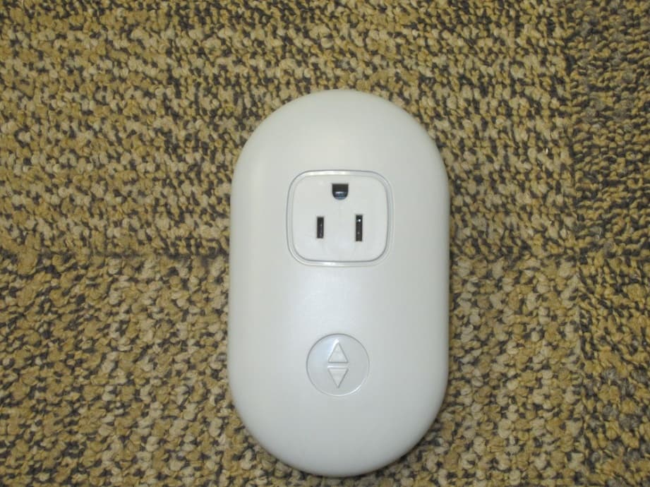
LPM-10000
May 20, 2015Smart Outlet
Equipment Class
DTS - Digital Transmission System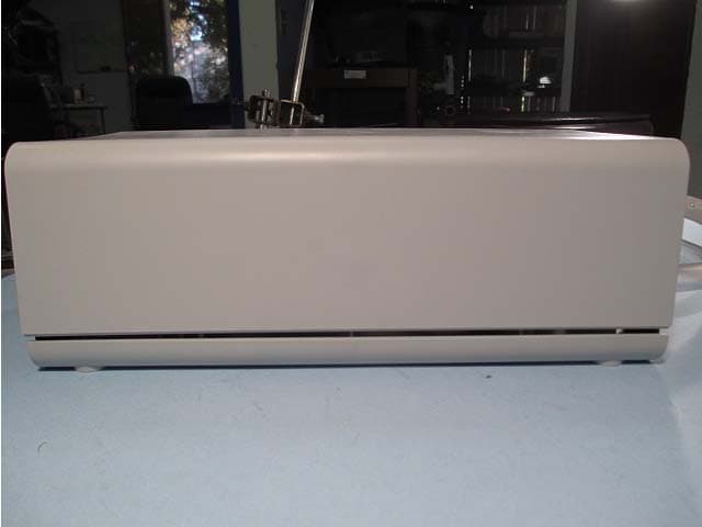
LPM-7000A
Feb 23, 2014Sleep monitoring and tracking system with the ability to monitor heart rate, respiration rate, and motion.
Equipment Class
DTS - Digital Transmission System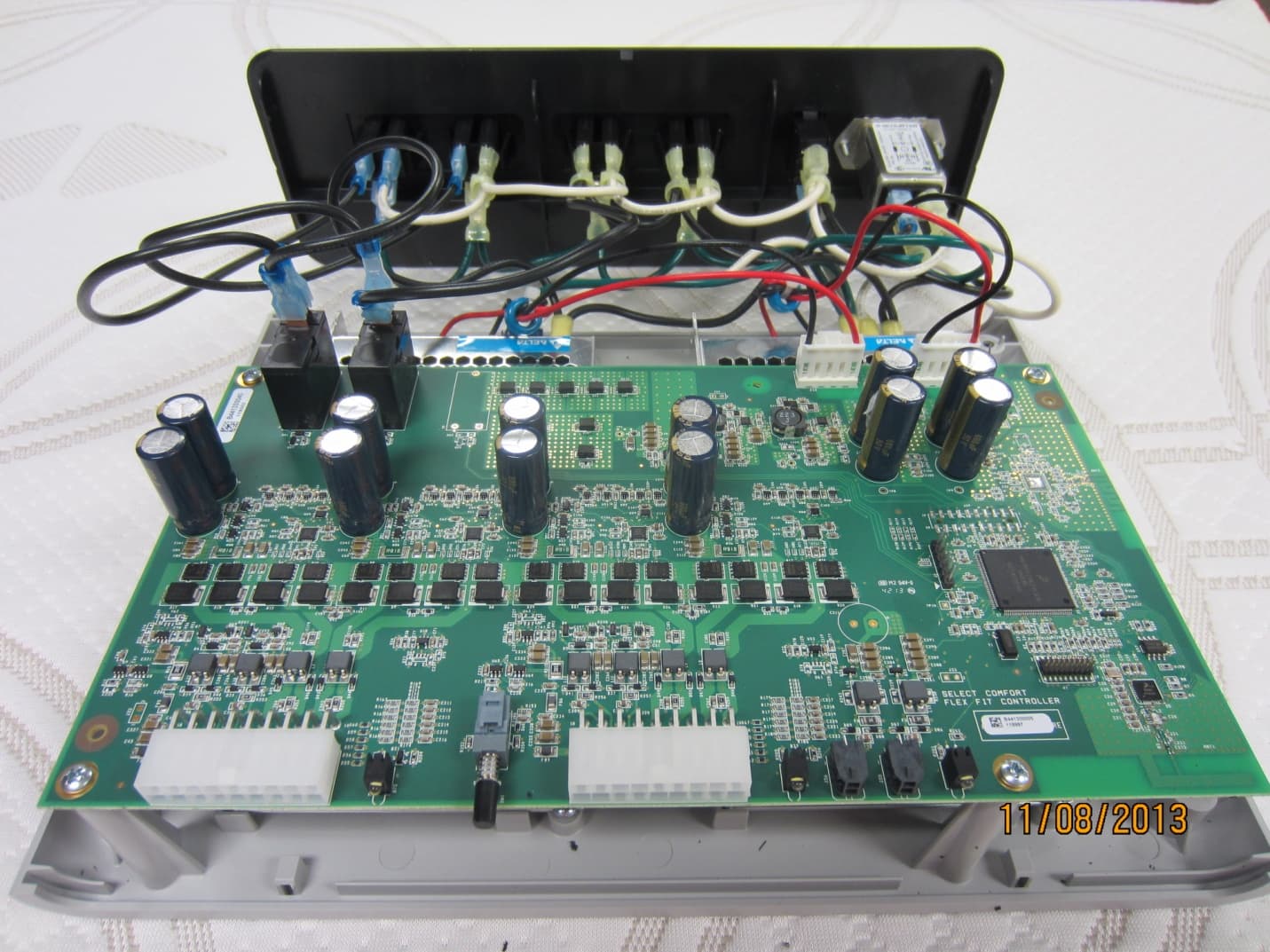
LPM-9000A
Dec 01, 2013Select Comfort Flex Fit
Equipment Class
DTS - Digital Transmission SystemLPM-6000A
Mar 21, 2013Dual Temperature Engine
Equipment Class
DXX - Part 15 Low Power Communication Device Transmitter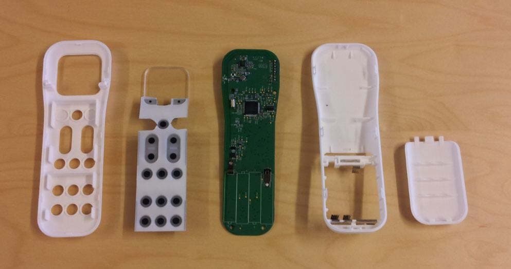
LPM-1000G
Jun 05, 2012Adjustable Foundation Remote
Equipment Class
DSC - Part 15 Security/Remote Control Transmitter