LPM-9000ASelect Comfort Flex Fit
Sleep Number Corporation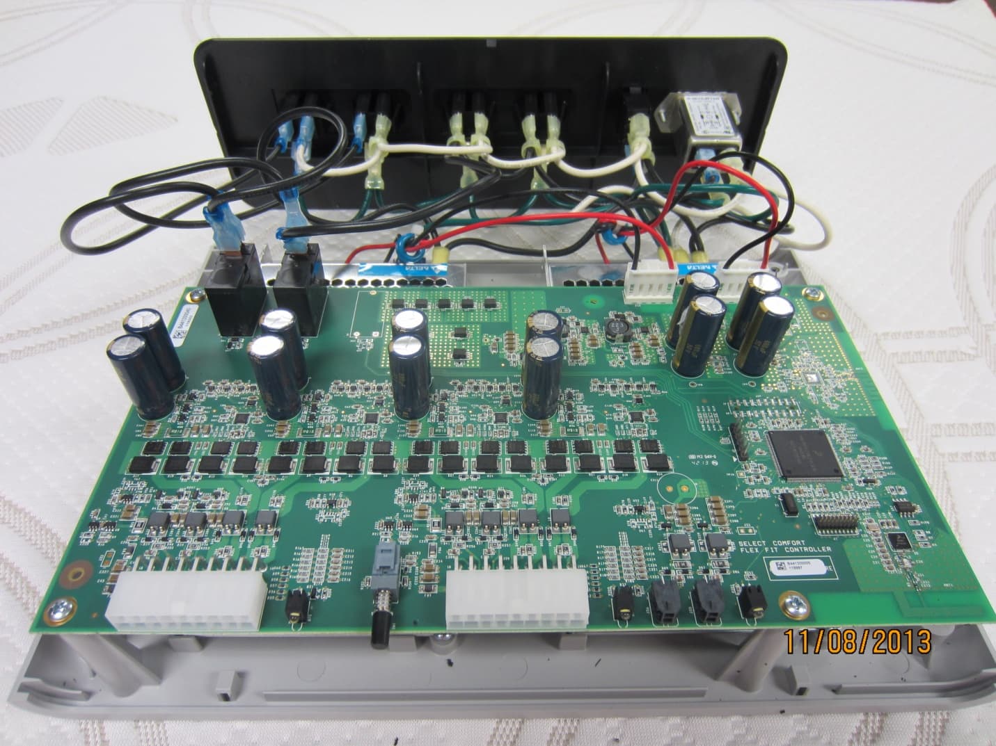
Click to zoom
Application Details
- Equipment Class
- DTS - Digital Transmission System
- Date of Grant
- Dec 01, 2013
- Application Purpose
- Original Equipment
- Date of Application
- Dec 01, 2013
- Equipment Note
- Select Comfort Flex Fit
- Frequency Range
- 2405.00000000 - 2480.00000000
- Company
- Sleep Number Corporation
- Country
- United States
Documents & Files
Document Text
Text extracted from the exhibit documents filed with the FCC. Open a document above to read the original.
Users Manual
FlexFit ™ adjustable base us er guide ® SLEEP NUMBER, SELECT COMFORT and the Double Arrow Design are registered trademarks of Select Comfort Corporation. Congratulations You’re about to take individualized comfort of your sleep Number ® bed to the ultimate level. by adding a FlexFit ™ adjustable base, you’re creating an even more individualized sleep environment and enhancing the customized comfort of the bed that can significantly improve your sleep quality. a t sl eep Number, ® we’re dedicated to improving your sleep with new and innovative products—everything from beds to bedding solutions designed to help you sleep just right. We know that you, too, will fall in love with s l eep Number ® comfort, quality, and customer service—and a truly individualized sleep experience. Copy above is FpO. j ohn/brad/annie requested re-write. FpO 2 What’s inside Congratulations! Your new sleep Number ® FlexFit ™ adjustable base is set up and ready to enjoy. inside, you’ll find instructions for the easy-to-use remote. Whether reading, relaxing or sleeping soundly, we know you’ll fall in love with comfort you can adjust in every way. look to Sleep Number for innovations with your individual needs in mind. FlexFit ™ base: What’s included................................................................pg 4 Your FlexFit ™ base at a glance ................................................................pg 6 im portant s a fety i n structions ..................................................................pg 8 advisory ....................................................................................................pg 9 product Care .............................................................................................pg 12 Frequently asked Questions ..................................................................pg 14 Optional a c cessories ...............................................................................pg 16 3 Twin Full/ Queen King Split/ FlexTop ™ King Remote1112 FlexFit ™ Control ™ System 1111 4-inch Legs4488 Casters4488 Mattress Retainer Kit1122 Bed Strap Kit King bases only 0011 Power Cord1111 Under-bed Lights FlexFit ™ 3 only 1222 FlexFit ™ base: What’s included assembling Your FlexFit ™ adjustable base Carefully check the contents of your boxes. make sure you have the correct number of components for the size of bed you purchased. if you are missing any items listed to the right, please call 1.800.472.7185 or email Customer service at [email protected] before You begin Copy above is FpO. j ohn/brad/annie requested re-write. 4 RemoteFlexFit ™ Control System 4-inch Legs Mattress Retainer Kit Casters Bed Strap KitPower CordUnder-bed Lights a s sembling Your FlexFit ™ a dj ustable b as e FlexFit ™ base Components may vary by model FlexFit ™ onlyKing bases only may vary by model FpO 5 Your FlexFit ™ base at a glance A L eft FlexFit ™ Adjustable Base B Right FlexFit ™ Adjustable Base C J unction Cables D FlexFit ™ Control System Back E FlexFit ™ Control System Front D C BA E Full/Queen tw inKing ma ttress mattressmattress Foot of bed may vary by model 6 FlexFit ™ Control ™ s ystem Your FlexFit ™ Control system at a glance A P ower Cord Connector Connect the aC power cord. B R eset Button resets the FlexFit ™ control system. C Outlets (FlexFit ™ 3 only) Constant power for your Firmness Control ™ system, alarm clock, etc. D L eft Night Stand (FlexFit ™ 3 only) in dependent control of left night stand lamp from remote. E R ight Night Stand (FlexFit ™ 3 only) in dependent control of right night stand lamp from remote. F L eft Sleep Number ® FlexFit ™ Base Connection (King Only) G R ight Sleep Number ® FlexFit ™ Base Connection (King Only) H F lat Base Button pr ess to return base to flat position. I Nightlight (FlexFit ™ 3 only) Connection for under-bed light(s). ABCDE FGHI Front b ack FpO FpO 7 important safety instructions When using an electrical furnishing, basic precautions should always be followed, including the following: daNger – to reduce the risk of electric shock: 1. always unplug this furnishing from the electrical outlet before cleaning. WarNiNg – to reduce the risk of burns, fire, electric shock, or injury to persons: 1. unplug from outlet before putting on or taking off parts. 2. Close supervision is necessary when this furnishing is used by, or near children, invalids, or disabled persons. 3. use this furnishing only for its intended use as described in these instructions. do not use attachments not recommended by the manufacturer. 4. Never operate this furnishing if it has a damaged cord or plug, if it is not working properly, if it has been dropped or damaged, or dropped into water. return the furnishing to a service center for examination and repair. 5. K eep the cord away from heated surfaces. 6. Never operate the furnishing with the air openings blocked. Keep the air openings free of lint, hair, and the like. 7. Never drop or insert any object into any opening. 8. do not use outdoors. 9. d o n ot operate where aerosol (spray) products are being used or where oxygen is being administered. 10. to disconnect, turn all controls to the off position, then remove plug from outlet. 11. Contains always On receptacles. to reduce risk of electric shock – disconnect power strip from power source before servicing any equipment connected to the power strip. 12. N ever place items on top of the control box. 13. F or grounded products the following statement: WarNiNg: risk of electric shock – Connect this furnishing to a properly grounded outlet only. saVe tHese iNstruCtiONs. grOuNdiNg iNstruCtiONs (a) For all grounded, cord-connected products: this product must be grounded. if it should malfunction or breakdown, grounding provides a path of least resistance for electric current to reduce the risk of electric shock. this product is equipped with a cord having an equipment-grounding conductor and a grounding plug. the plug must be plugged into an appropriate outl…
Text truncated - open the document above for the full version.
Cover Letter(s)
WTD 13.4.9 FCC Compliance Opinion LGPD0118 Information about the Applicant Grantee (Company Name) Select Comfort Corporation FCC Contact Person Jeffrey Barnum Address 9800 59th Avenue North City, State, Zip Minneappolis, MN 55442 Job Number LGPD0118 Model Flex Fit FCC ID LPM-9000A Agent Approval Type Original Equipment Class DTS Digital Transmission System Rule Part 15.247 Overview This application is for the original certification of a Select Comfort Flex Fit remote with 2.4 GHz transceiver operating under FCC rule part 15.247. Confidentiality requested for allowed files. Request is properly addressed and referenced. Recommendation All items have been resolved and completed to my satisfaction; therefore I recommend this application for approval. Signature Dave Tolman, TCB Committee 11/19/2013
External Photos
FCC Exhibit – External Photos Company: Select Comfort FCC ID: LPM-9000A Figure 1 - Assembly Components Top View (1) Figure 2 - Assembly Components Top View (2) Figure 3 - Assembly Components Top View (3) Figure 4 - Assembly Components Side View (1) Figure 5 - Assembly Components Side View (2) Figure 6 - Assembly Components Side View (3) Figure 7 - Assembled Controller Top View Figure 8 - Assembled Controller Bottom View Figure 9 - Assembled Controller Left View Figure 10 - Assembled Controller Right View Figure 11 - Assembled Controller Front View Figure 12 - Assembled Controller Back View
ID Label/Location Info
FCC Exhibit – FCC Image Location Company: Select Comfort FCC ID: LPM-9000A Figure 1 - Assembled Flex Fit Controller looking from bottom showing location where FCC ID will be embedded in the label Location of FCC ID Figure 2 - Detail showing FCC ID and required statement. Flex Fit Controller ID will be LPM-9000A (LPM-6000A shown in the picture will be replaced with LPM-9000A)
Internal Photos
FCC Exhibit – Internal Photos Company: Select Comfort FCC ID: LPM-9000A Figure 1 – Top Side of Circuit Board (1) Figure 2 – Top SSide of Circuuit Board (2) Figure 3 Bottom Side of Circuit Board Figure 4 - Detail of antenna and radio on top side of board. Radio Antenna
Operational Description
© Freescale Semiconductor, Inc., 2005, 2006, 2012. All rights reserved. Freescale Semiconductor Application Note Document Number: AN2731 Rev. 2, 12/2012 1Introduction With the introduction of many applications into the 2.4 GHz band for commercial and consumer use, Antenna design has become a stumbling point for many customers. Moving energy across a substrate by use of an RF signal is very different than moving a low frequency voltage across the same substrate. Therefore, designers who lack RF expertise can avoid pitfalls by simply following “good” RF practices when doing a board layout for 802.15.4 applications. The design and layout of antennas is an extension of that practice. This application note will provide some of that basic insight on board layout and antenna design to improve our customers’ first pass success. Antenna design is a function of frequency, application, board area, range, and costs. Whether your application requires the absolute minimum costs or minimization of board area or maximum range, it is important to understand the critical parameters so that the proper trade-offs can be chosen. Some of the parameters necessary in selecting the correct antenna are: antenna Compact Integrated Antennas Designs and Applications for the MC1321x, MC1322x, and MC1323x Contents 1 Introduction . . . . . . . . . . . . . . . . . . . . . . . . . . 1 2 Antenna Terms . . . . . . . . . . . . . . . . . . . . . . . . 2 3 Basic Antenna Theory . . . . . . . . . . . . . . . . . . 3 4 Impedance Matching . . . . . . . . . . . . . . . . . . . 5 5 Antennas . . . . . . . . . . . . . . . . . . . . . . . . . . . . . 8 6 Miniaturization Trade-offs . . . . . . . . . . . . . . 11 7 Potential Issues . . . . . . . . . . . . . . . . . . . . . . 12 8 Recommended Antenna Designs . . . . . . . . 13 9 Design Examples . . . . . . . . . . . . . . . . . . . . . 14 Compact Integrated Antennas Application Note, Rev. 2 2Freescale Semiconductor tuning, matching, gain/loss, and required radiation pattern. This note is not an exhaustive inquiry into antenna design. It is instead, focused toward helping our customers understand enough board layout and antenna basics to aid in selecting the correct antenna type for their application as well as avoiding the typical layout mistakes that cause performance issues that lead to delays. Additionally, several popular antennas are presented as possible solutions for some of the 802.15.4 applications. 2Antenna Terms Antenna GainA mathematical measure of an antenna radiation pattern compared to a reference antenna such as a dipole or an isotropic radiator. The gain is usually measured in dBs relative to a dipole or dBi relative to an ideal isotropic. In any given direction, a negative gain means that the antenna radiates less than the reference antenna and a positive number means that the antenna radiates more than the reference antenna. Decibel (dB)A logarithmic scale that represents power gain or loss in an RF circuit. 3 dB represents a doubling of power, -3 dB is half the power and -6 dB represents half the voltage or current, but a quarter of the power. (dBi) Application of the logarithmic scale to Antenna gain that is relative to an ideal isotropic antenna. Radiation ResistanceThe real part of an antenna's impedance that is associated with radiated power. Antenna EfficiencyIt is the ratio of the power radiated to the power delivered to the antenna input. Hence, an antenna with 50% efficiency has a ratio of 0.5 or -3 dB. Total efficiency includes antenna efficiency and also accounts for mismatch losses. Transmission LinesA physical means to transport an RF signal from one point to another, which is defined by its physical constraints to match the characteristic impedance of the system. Most common systems use 50 Ohms characteristic impedance. MicrostripA type of electrical transmission line that can be fabricated using printed circuit board technology, and is used to convey microwave-frequency signals. It consists of a conducting strip separated from a ground plane by a dielectric layer known as the substrate. StriplineA type of electrical transmission line that can be fabricated using printed circuit board technology, and is used to convey microwave-frequency signals. It consists of a flat strip of metal that is sandwiched between two parallel ground planes. The insulating material of the substrate forms a dielectric. The width of the strip, the thickness of the substrate, and the relative permittivity of the substrate determine the characteristic impedance of the strip, which is a transmission line . Compact Integrated Antennas Application Note, Rev. 2 Freescale Semiconductor3 3Basic Antenna Theory A common method to evaluate an antenna is to view its antenna gain pattern. An antenna's gain pattern is a measure of directionality of the antenna. A perfect theoretical omni-directional antenna radiates equally in all directions and its field would look like a perfect sphere. However, practical manufacturable antennas cannot be made to radiate equally in all directions. Therefore, all practical antennas will have some gain. The higher the gain the more directional is the antenna. Large distance fixed position applications actually require a highly directional antenna. Whereas, a general purpose local area network will usually require an antenna that is omni-directional. Theoretically, any metallic structure can be used as an antenna. However, some structures are more efficient in radiating and receiving RF power than others. Transmission lines are used to convey the signal between the radio and the antenna with minimum loss due to resistive, mismatch and radiative losses as possible. The following examples explain these concepts. Transmission lines take on a variety of shapes such as microstrip, coplanar waveguide, stripline, coaxial lines, etc.. For 802.15.4 applications built on FR4 substrates, the methods of transmission lines typically take the form of microstrip, or coplanar…
Text truncated - open the document above for the full version.
RF Exposure Info
Compliance with 47 CFR 15.247(i) “Systems operating under the provisions of this section shall be operated in a manner that ensures that the public is not exposed to radio frequency energy levels in excess of the Commission's guidelines. See § 1.1307(b)(1) of this chapter.” The EUT provides wireless control for an adjustable bed. It will be installed greater than 20 cm from the user’s head or torso. However, due to its low output power, there is no restriction from placing it within 20cm of the user. The maximum antenna gain of the Inverted-F, PCB trace antenna is 2.5 dBi. The maximum peak conducted output power is 0.047 mW. The maximum peak radiated power is 0.08 mW EIRP for FCC ID: LPM-9000A. The transmit frequency is 2405 to 2480MHz, therefore the EUT does not require routine SAR evaluation because it falls below the low power threshold of 60/f(GHz)mW. Please see this excerpt from KDB 447498 D01 Mobile Portable RF Exposure v05r01, Section 4.3.1, Item #1: “The 1-g and 10-g SAR test exclusion thresholds for 100 MHz to 6 GHz at test separation distances ≤ 50 mm are determined by: [(max. power of channel, including tune-up tolerance, mW)/(min. test separation distance, mm)] · [√f(GHz)] ≤ 3.0 for 1-g SAR and ≤ 7.5 for 10-g extremity SAR, where • f(GHz) is the RF channel transmit frequency in GHz • Power and distance are rounded to the nearest mW and mm before calculation • The result is rounded to one decimal place for comparison • 3.0 and 7.5 are referred to as the numeric thresholds in the step 2 below The test exclusions are applicable only when the minimum test separation distance is ≤ 50 mm and for transmission frequencies between 100 MHz and 6 GHz. When the minimum test separation distance is < 5 mm, a distance of 5 mm according to 5) in section 4.1 is applied to determine SAR test exclusion.” Using the most conservative exposure condition (closest to the user), the applicant’s wireless radio, FCC ID: LPM-9000A, is compliant with the requirements of FCC 15.247(i). Per KDB 447498 it is excluded from SAR testing and deemed compliant. Using the equation above: (0.08mW / 5mm)*2.48GHz = 0.04 which is < 3.0 for 1-g SAR.
Test Report
Select Comfort Corp Adjustable Foundation Controller Board FCC 15.247:2013 2.4 GHz DTS Radio Report #: LGPD0118 Report Prepared By Northwest EMC Inc. NORTHWEST EMC – (888) 364-2378 – www.nwemc.com California – Minnesota – Oregon – New York – Washington WTD 12.5.23 CERTIFICATE OF TEST Last Date of Test: November 01, 2013 Select Comfort Corp Model: Adjustable Foundation Controller Board Emissions Test Description Specification Test Method Pass/Fail Output Power FCC 15.247:2013 ANSI C63.10:2009 Pass Power Spectral Density FCC 15.247:2013 ANSI C63.10:2009 Pass Occupied Bandwidth FCC 15.247:2013 ANSI C63.10:2009 Pass Spurious Conducted Emissions FCC 15.247:2013 ANSI C63.10:2009 Pass Band Edge Compliance FCC 15.247:2013 ANSI C63.10:2009 Pass Spurious Radiated Emissions FCC 15.247:2013 ANSI C63.10:2009 Pass Powerline Conducted Emissions FCC 15.207:2013 ANSI C63.10:2009 Pass Deviations From Test Standards None Approved By: Tim O'Shea, Operations Manager NVLAP Lab Code: 200881-0 This report must not be used to claim product certification, approval, or endorsement by NVLAP, NIST, or any agency of the federal government of the United States of America. Product compliance is the responsibility of the client, therefore the tests and equipment modes of operation represented in this report were agreed upon by the client, prior to testing. This Report may only be duplicated in its entirety. The results of this test pertain only to the sample(s) tested. The specific description is noted in each of the individual sections of the test report supporting this certificate of test. REV 2012.08.02 REVISION HISTORY Revision Number Description Date Page Number 00 None Barometric Pressure The recorded barometric pressure has been normalized to sea level. REV 2012.05.24 ACCREDITATIONS AND AUTHORIZATIONS United States FCC - Designated by the FCC as a Telecommunications Certification Body (TCB). Certification chambers, Open Area Test Sites, and conducted measurement facilities are listed with the FCC. A2LA - Accredited by A2LA to ISO / IEC Guide 65 as a product certifier. This allows Northwest EMC to certify transmitters to FCC and IC specifications. NVLAP - Each laboratory is accredited by NVLAP to ISO 17025 Canada IC - Recognized by Industry Canada as a Certification Body (CB). Certification chambers and Open Area Test Sites are filed with IC. European Union European Commission – Validated by the European Commission as a Conformity Assessment Body (CAB) under the EMC directive and as a Notified Body under the R&TTE Directive. Australia/New Zealand ACMA - Recognized by ACMA as a CAB for the acceptance of test data. Korea KCC / RRA - Recognized by KCC’s RRA as a CAB for the acceptance of test data. Japan VCCI - Associate Member of the VCCI. Conducted and radiated measurement facilities are registered. Taiwan BSMI – Recognized by BSMI as a CAB for the acceptance of test data. NCC - Recognized by NCC as a CAB for the acceptance of test data. Singapore IDA – Recognized by IDA as a CAB for the acceptance of test data. Hong Kong OFTA – Recognized by OFTA as a CAB for the acceptance of test data. Vietnam MIC – Recognized by MIC as a CAB for the acceptance of test data. Russia GOST – Accredited by Certinform VNIINMASH, CERTINFO, SAMTES, and Federal CHEC to perform EMC and Hygienic testing for Information Technology products to GOST standards. SCOPE For details on the Scopes of our Accreditations, please visit: http://www.nwemc.com/accreditations/ REV 2013.03.8 MEASUREMENT UNCERTAINTY Measurement Uncertainty When a measurement is made, the result will be different from the true or theoretically correct value. The difference is the result of tolerances in the measurement system that cannot be completely eliminated. To the extent that technology allows us, it has been our aim to minimize this error. Measurement uncertainty is a statistical expression of measurement error qualified by a probability distribution. A measurement uncertainty estimation has been performed for each test per our internal quality document WP 342. The estimation is used to compare the measured result with its "true" or theoretically correct value. The expanded measurement uncertainty (K=2) for each test is listed below. Our measurement data meets or exceeds the measurement uncertainty requirements of the applicable specification; therefore, the test data can be compared directly to the specification limit to determine compliance. The calculations for estimating measurement uncertainty are based upon ETSI TR 100 028 (or CISPR 16-4-1 as applicable), and are available upon request. The following table represents the Measurement Uncertainty (MU) budgets for each of the tests that may be contained in this report. Test + MU - MU Frequency Accuracy (Hz) 0.12 -0.01 Amplitude Accuracy (dB) 0.49 -0.49 Conducted Power (dB) 0.41 -0.41 Radiated Power via Substitution (dB) 0.69 -0.68 Temperature (degrees C) 0.81 -0.81 Humidity (% RH) 2.89 -2.89 Field Strength (dB) 3.80 -3.80 AC Powerline Conducted Emissions (dB) 2.94 -2.94 REV 2013.06.28 FACILITIES Oregon Labs EV01-12 22975 NW Evergreen Pkwy Hillsboro, OR 97124 (503) 844-4066 California Labs OC01-13 41 Tesla Irvine, CA 92618 (949) 861-8918 New York Labs NY01-04 4939 Jordan Rd. Elbridge, NY 13060 (315) 685-0796 Minnesota Labs MN01-08 9349 W Broadway Ave. Brooklyn Park, MN 55445 (763) 425-2281 Washington Labs NC01-05,SU02,SU07 19201 120 th Ave. NE Bothell, WA 98011 (425) 984-6600 VCCI A-0108 A-0029 A-0109 A-0110 Industry Canada 2834D-1, 2834D-2 2834B-1, 2834B-2, 2834B-3 2834E-1 2834C-1 NVLAP NVLAP Lab Code: 200630-0 NVLAP Lab Code: 200676-0 NVLAP Lab Code: 200761-0 NVLAP Lab Code: 200881-0 NVLAP Lab Code: 200629-0 WTD 12.5.23 PRODUCT DESCRIPTION Client and Equipment Under Test (EUT) Information Company Name: Select Comfort Corp Address: 9800 59 th Ave N City, State, Zip: Minneapolis, MN 55442 Test Requested By: Rick Kinnunen Model: Adjustable Foundation Controller Board First Date of Test: October 18, 2013 Last Date of…
Text truncated - open the document above for the full version.
Test Setup Photos
Output Power XMit 2013.08.15 NORTHWEST Output Power PsaTx 2013.08.16 EMC Direct Connect (1).JPG Direct Connect (2).JPG Output Power Power Spectral Density XMit 2013.08.15 NORTHWEST Power Spectral Dens PsaTx 2013.08.16 EMC Direct Connect (1).JPG Direct Connect (2).JPG Power Spectral Density Occupied Bandwidth XMit 2013.08.15 NORTHWEST Occupied Bandwidth PsaTx 2013.08.16 EMC Direct Connect (1).JPG Direct Connect (2).JPG Occupied Bandwidth Spurious Conducted Emissions XMit 2013.08.15 NORTHWEST Spurious Conducted PsaTx 2013.08.16 EMC Direct Connect (1).JPG Direct Connect (2).JPG Spurious Conducted Emissions Band Edge Compliance XMit 2013.08.15 NORTHWEST Band Edge Complian PsaTx 2013.08.16 EMC Direct Connect (1).JPG Direct Connect (2).JPG Band Edge Compliance photo SE (1).JPG SE (2).JPG Spurious Radiated Emissions PSA-ESCI 2012.12.14 photo SE (3).JPG Spurious Radiated Emissions PSA-ESCI 2012.12.14 WTD.2013.07.23, PSA-ESCI 2012.12.14, PSA-ESCI Version 2013.2.20 POWERLINE CONDUCTED EMISSIONS
Contact Information
Applicant
Jeff Barnum(VP of Manufacturing Operations)
Test Firm
Northwest EMC, Inc.Greg Kiemel
Technical Specifications
| # | Rule Parts | Frequency Range | Power Output |
|---|---|---|---|
| 1 | 15C | 2.40 GHz - 2.48 GHz | 47.00 µW |
Other Applications from Sleep Number Corporation
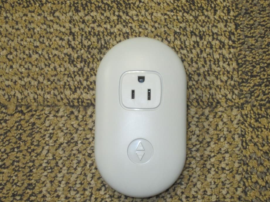
LPM-10000
May 20, 2015Smart Outlet
Equipment Class
DTS - Digital Transmission System
LPM-7000A
Feb 23, 2014Sleep monitoring and tracking system with the ability to monitor heart rate, respiration rate, and motion.
Equipment Class
DTS - Digital Transmission SystemLPM-6000A
Mar 21, 2013Dual Temperature Engine
Equipment Class
DXX - Part 15 Low Power Communication Device Transmitter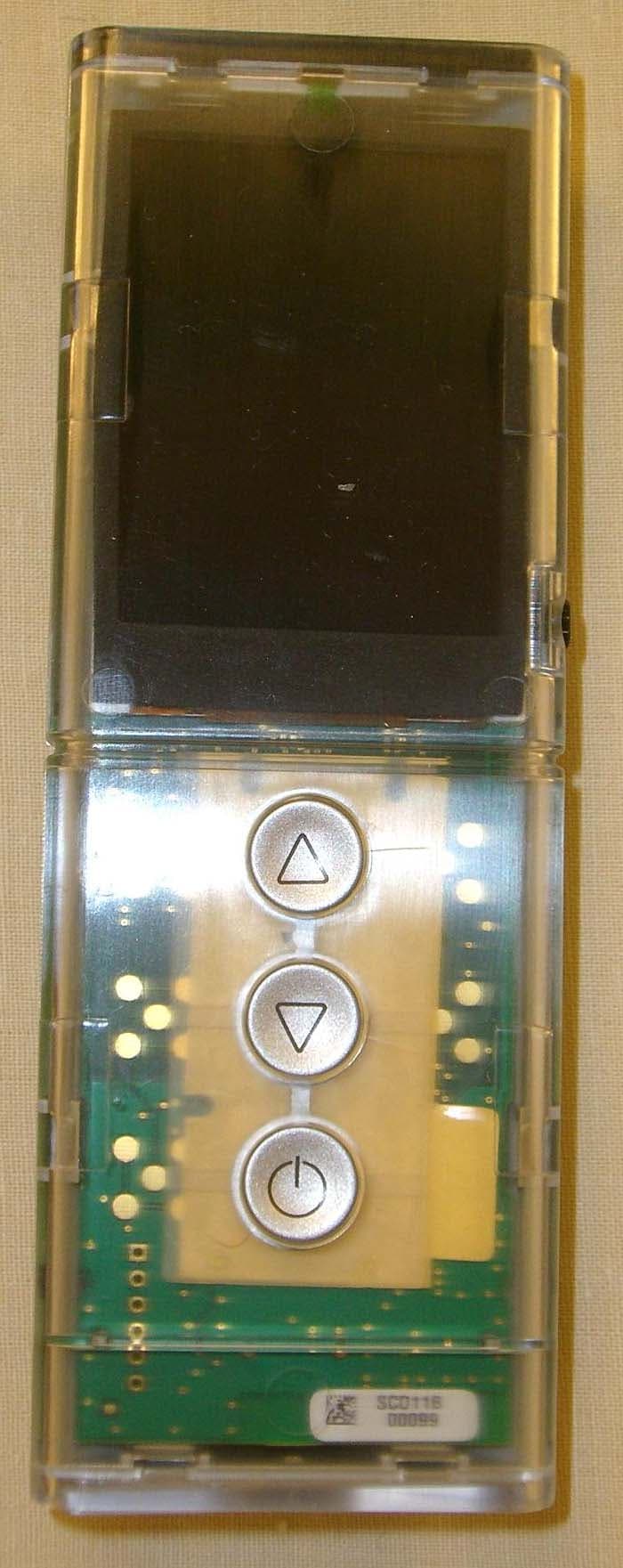
LPM-5000A
Mar 10, 2013NXT Remote
Equipment Class
DXX - Part 15 Low Power Communication Device Transmitter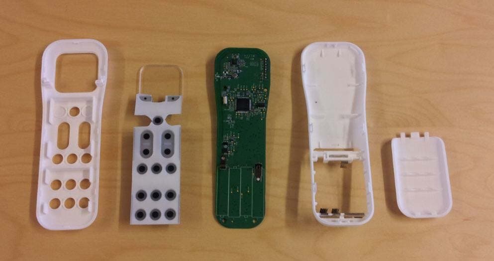
LPM-1000G
Jun 05, 2012Adjustable Foundation Remote
Equipment Class
DSC - Part 15 Security/Remote Control Transmitter