LPM-3000HPart 15 Low Power Communication Device Transmitter
Sleep Number Corporation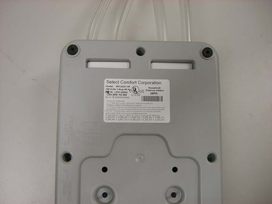
Click to zoom
Application Details
- Equipment Class
- DXX - Part 15 Low Power Communication Device Transmitter
- Date of Grant
- Nov 01, 2007
- Application Purpose
- Original Equipment
- Date of Application
- Nov 01, 2007
- Equipment Note
- Part 15 Low Power Communication Device Transmitter
- Frequency Range
- 2405.00000000 - 2480.00000000
- Company
- Sleep Number Corporation
- Country
- United States
Documents & Files
Document Text
Text extracted from the exhibit documents filed with the FCC. Open a document above to read the original.
Users Manual
Welcome to your Sleep Number ® Bed X 4000 and 5000 model assembly instructions inside 45 80 35 70 Welcome and Congratulations 55 Welcome and Congratulations, Congratulations on your purchase of The Sleep Number Bed by Select Comfort ™ ! You’re about to join more than 5 million people who’ve traded their innerspring mattresses for the most innovative sleep surface ever. The technology behind the SLEEP NUMBER ® bed is one that recognizes the unique sleeping needs of every individual, which vary according to comfort preference, body type, height, weight, sleeping position, and other health and lifestyle factors. By creating a fully personalized sleep surface, your new Sleep Number ® bed offers you customized comfort that can signifi cantly improve your sleep quality. You’ll enjoy years of the latest generation of sleep comfort and technology in your Sleep Number ® bed. Our commitment to constant innovation, value and customer satisfaction has repeatedly earned us the Consumers Digest Best Buy award. Sleep Number ® bed owners like you have made us the No. 1 bedding retailer year after year, as ranked by Furniture/Today. We invite you to tell your friends and neighbors about this revolutionary product that can help them attain the most comfortable sleep possible. When your referral results in a purchase, you’ll earn valuable rewards* that will make it easier for you to add another Sleep Number ® bed to your home and ensure improved sleep for your children or your guests. We thank you for your purchase and wish you years of personal comfort and restful sleep. William R. McLaughlin President & CEO My Sleep Number ® is 55 1 * See Owners’ COMFORT CLUB ® Rewards on page 38. Foundation Assembly WHAT’S INSIDES ettin g up y our new S L EE P N UMB E R ® bed onl y takes about an hour, but y ou’ll en j o y the benefits of better sleep for y ears to come. You won’t need an y tools and, althou g h it’s nice to have a helper, y ou can do it b y yoursel f . First, you’ll need to remove your old bed. N e xt, we’ ll gui d e you step- b y-step t h roug h assem bl ing t h e foundation, positionin g the mattress and attachin g the Firmness Control ™ S y s t em. T hen, y ou’ll learn how to find yo u r S l eep N umber ® sett i ng. A nd, fi nally, the best part—you can luxuriate in the personalized com f ort o f your S l ee p N u m be r ® bed. u Foundation Assembl y .................................... p g 3 u M attress Assem bly ......................................... pg 11 u Firmness Contro l ™ S ystem ............................. pg 23 u FCC Users In f ormation .................................. pg 2 6 u M attress C are ................................................. pg 3 1 u A ccesso ri es ..................................................... p g 33 u Warrant y and Comfort Club ® ......................... p g 3 5 2 3 Note: Texture and surface appearance may vary . Foundation Assembly 4 BEFORE YOU BEGIN X Carefully check the contents of your foundation boxes X Decide where to put your new bed X Make sure there’s an electric power source nearby for use with your Firmness Control ™ System X Assemble your bed frame if you have one Your foundation should be assembled directly onto your bed frame or on the fl oor. Some bed frames have slats that run from one side of the bed to the other. If your bed frame has slats, position the slats evenly to support the foundation. If your bed frame has fewer than three slats, we recommend adding additional slats to ensure adequate support for your foundation. Caution: With some styles of bed frames, the foundation length may extend beyond the frame’s support legs. This situation makes it possible for the frame to tip when signifi cant weight is placed at the foot of the bed. Please use caution when sitting or placing weight on the foot of the bed when using these types of frames. X King foundation The King foundation consists of two Twins side by side. Complete the assembly of one unit, assemble the second, then place side by side on the bed frame. If you are missing any items listed on the following page, please e-mail Customer Service at customerservice@ selectcomfort.com or call 1.800.472.7185 TROUBLESHOOTING For answers to some common questions regarding your foundation, see the Frequently Asked Questions at the end of this section. “ I assembled the Sleep Number bed by myself. My wife was in doubt at fi rst, but, after sleeping one night, she said, it was magic how well she slept without back pain. Now we sleep longer and more comfortably than any previous mattress we’ve owned.” - C. Clark Shedd, Tucson, AZ 2 each 2 each 2 each 4 each 6 6 6 12 2 4 4 4 2 2 2 4 1 1 1 1 0 0 4 0 Twin Full Queen King CONTENTS Carefully check the contents of your foundation boxes and compare with the list below. Each component is clearly labeled with the part name and part number. Side Rails Support /End Beams Texture and surface appearance may vary Pin Components QUANTITY 5 Expanded Queen only Corner Brackets Packaged in the mattress box Deck Panels Texture and surface appearance may vary Fabric Coverlet Packaged in the mattress box Shown as packaged B A 1 CONNECT SIDE RAILS Push the components labeled A side rail and B side rail together. Joints fi t tightly. Push fi rmly. 2 INSERT PIN Slide pins in, “T” end up. Push fi rmly. 6 B A 7 3 INSERT SUPPORT/ END BEAMS For Twin, Queen and Eastern King models: – insert support beams with tabs up and textured side out. For Full and California King models: – insert labeled end beams followed by remaining support beams with tabs up. Joints fi t tightly. Push fi rmly until top is fl ush. Expanded Queen models only Attach a corner bracket over each end before connecting to the side rail. Pin Pin 4 INSERT SUPPORT BEAMS Tabs up, match “A” end with “A” groove; match “B” end with “B” groove. Joints fi t tightly, push fi rmly until top is fl ush. Slide the remaining support beams into the next set of channels. A B A B he A B A B 8 5 PLACE DECK PANELS Slide pa…
Text truncated - open the document above for the full version.
Users Manual
19 YOU’RE DONE! NEXT STEP X THE FIRMNESS CONTROL ™ SYSTEM 10 11 VERIFY BORDER WRAP POSITIONING Verify that the border wrap extends over the Intralux ® foam comfort pad. MATTRESS COVER Zip the top of the mattress cover. Store air chamber caps inside mattress at head of bed . Color and pattern may vary. Important Notice: To ensure compliance with federal and state fl ammability requirements, the border wrap must be positioned correctly within the mattress as shown in the steps below. The caps are in the Firmness Control ™ System box. Please store these in the mattress cover in case you should ever want to disassemble your bed and temporarily cap your air chamber(s). Where are the caps for air chamber(s)? And where should I store them? What if my Intralux ® foam comfort pad appears to be too small or irregular? Gently shake the pad as you place it on your mattress and it will recover its full size overnight. What do I do if the Firmness Control ™ System doesn’t run? Make sure the power cord is securely plugged into the Firmness Control ™ System and the wall outlet. Check to see if the power cord is plugged into an outlet that has power and is not connected to an on/off wall switch. What if I feel like I’m rolling toward the edge or toward the center of the mattress? Although rare, these sensations could potentially be experienced if one side of the mattress is set quite fi rm and the other side quite soft. Call Customer Service for a remedy to this situation if it is bothersome to you. 20 Mattress Frequently Asked Questions The odor you may smell is non-toxic and will fade over time. To minimize the smell, allow the air chamber to air out for a few hours and then lay a couple of dryer sheets on top of the air chamber. What if I notice a rubber smell from the air chamber? Will my bed defl ate if there is a power surge or power loss? No, your mattress will maintain its fi rmness. To protect your Firmness Control ™ System, we do recommend using a surge protector. The mattress is losing air. What should I do? The air loss could be caused by either the air chamber or the Firmness Control ™ System. To determine which component is causing the air loss, follow these troubleshooting steps: • Infl ate the side of the bed that is losing air to the preferred SLEEP NUMBER ® setting plus fi ve (i.e., if you sleep at a setting of 40, infl ate the bed to 45). • Locate the caps, and cap the side of the bed that is losing air. The assembly instructions suggested storing the air chamber caps in the mattress cover, at the head of the bed, where the zipper starts/ends. • Leave the air chamber capped for at least eight hours. It is preferable to cap it overnight while sleeping on it. • Contact Customer Service with the results of the troubleshooting. They will facilitate a component replacement under the terms of the warranty. 21 22 For the best looking, most crisp appearance, customers should fully infl ate the mattress (10 0 if using a digital Sleep Number ® remote). If going to full infl ation does not help with body impressions in the cover, the quilted top can be removed and shaken to restore some of the loft to the fi berfi ll. In addition, a vacuum nozzle may be used to fl uff the cover in areas where the fi bers have settled from use. Body impressions in a normal innerspring mattress would be an indication that the spring support is compressing or breaking down. The Sleep Number ® bed uses air to support your body. Since air cannot break down, you receive the same support after years of use as you do on the fi rst day of use. Please contact Customer Service with further questions. Why are there body impressions on the mattress cover? Mattress Frequently Asked Questions If you still have questions or need assistance, look for answers on our Web site sleepnumber.com or please call Customer Service at 1.800.472.7185 Firmness Control ™ System 23 24 25 FirmnessControl ™ System THINGS TO REMEMBERu Reasons to alter the firmness of your bed - strained muscles- back pain- weight change- pregnancy- sunburn- new sleep position as well as - to facilitate getting out of bed, if needed- to achieve a fuller bed appearance u Dual Adjustability If you purchased a dual chamber model, you have the ability to personalize each side of your SLEEP NUMBER ® bed. Since no two body types are the same, each sleep partner should find their own comfort level.If your model came with one remote for a dual chamber bed, the “L” button on the remote corresponds to the left side of the bed (left is determined when lying on your back on the bed). If you are missing any items listed on the following page, please e-mail Customer Service at [email protected] or call 1.800.472.7185TROUBLESHOOTINGFor answers to some common questions regarding your Firmness Control ™ System, see the Frequently Asked Questions at the end of this section. WHAT IS A SLEEP NUMBER ® SETTING? Your Sleep Number ® is a setting between 0 – 100 that represents the ideal combination of mattress comfort, firmness and support for your body, giving you the best night’s sleep possible. YOUR SLEEP NUMBER ® SETTING When you shopped for The Sleep Number Bed by Select Comfort ™ , you may have discovered your Sleep Number ® setting. You should use this as a starting point when setting the firmness of your Sleep Number ® mattress. If you don’t have your Sleep Number ® setting, this section will take you through the process of finding your Sleep Number ® setting and will provide you with additional information about your Sleep Number ® bed. If you don’t already have your Sleep Number ® setting or if you would like to experiment with finding a different Sleep Number ® setting, use the instructions below. EVALUATING YOUR COMFORT LEVELAs you are customizing the Sleep Number ® bed for your optimum comfort level, you will want to evaluate your sleep position and determine how you feel as compared to the diagrams below, then make adjustments to your firmness or pillow if ne…
Text truncated - open the document above for the full version.
Attestation Statements
TÜV America Inc. Phone: (651) 638-0297 19333 Wild Mountain Road Fax: (651) 638-0298 Taylor Falls, MN 55084 E-mail: [email protected] www.TUVamerica.com Management Service • Product Service • Industry Service • Automotive • BABT TÜV America Inc. is a subsidiary of TÜV SÜD Group. TÜV AMERICA INC 19333 WILD MOUNTAIN ROAD TAYLORS FALLS, MINNESOTA 55084-1786 ENGINEERING STATEMENT For Certification of Select Comfort RFCS Wireless Base Unit Model No: XX-YR FCC ID: LPM-3000H FRN: 0010433639 I am an Electromagnetic Compatibility Engineer for TÜV AMERICA INC, Taylors Falls, Minnesota. My education and experience are a matter of record with the Federal Communications Commission. TÜV AMERICA INC has been authorized by Doug Scites, Vice-President of Research and Development, of Select Comfort, to make Certification measurements of the above mentioned equipment. I attest that all testing done under my supervision was done in accordance with, and that the EUT fulfills the requirements of, the Federal Communications Commission's CFR 47 Part 15.249. Joel T. Schneider Senior Engineer Minnesota Wild River Lab TÜV America Product Service Tel: 651 604 4582 Fax: 651 638 0298 [email protected] Dated: 22 October 2007
Cover Letter(s)
TÜV America Inc. Phone: (651) 631-2487 1775 Old Highway 8 NW Fax: (651) 638-0285 Suite 104 E-mail: [email protected] New Brighton, MN 55112 www.TUVamerica.com Management Service • Product Service • Industry Service • Automotive • BABT TÜV America Inc. is a subsidiary of TÜV SÜD Group. 01 November 2007 American TCB 6731 Whittier Avenue McLean VA 22101 RE: Select Comfort Response to 102607 Comments FCC ID: LPM-3000H In response to your comments on the above submittal: 1. ATCB Comments: Please revise the confidentiality letter to exclude the parts list exhibit as there was not a parts list exhibit uploaded. FCC requires confidential request to match the upload to the FCC. RESPONSE: Uploaded revised exhibit. 2. ATCB Comments: Radiated test setup photos must show the antenna that was being used at the time of the tests. Please revise test setup photos. RESPONSE: A revised report has been uploaded. 3. ATCB Comments: Please upload bandedge plots that show the EUT stays within the 2400-2483.5 MHz bandwidth. RESPONSE: See pages 18 - 19 of the test report. Please let us know if anything further is required. Susan L Rupp, Technical Writer TÜV America Inc Tel: 651 638 4585 / Fax: 651 638 0298 [email protected]
External Photos
Select Comfort Base Top and Front Select Comfort Base Top and Back Select Comfort Base Left Side Select Comfort Base Right Side Select Comfort Base Bottom
ID Label/Location Info
Select Comfort Base Label Select Comfort Base Label Placement
Internal Photos
Select Comfort Base Interior View Select Comfort Base Top Board Select Comfort Base Back Board
Test Report
TÜV AMERICA INC 19333 Wild Mountain Road Taylors Falls MN 55084-1758 Tel: 651 638 0297 Fax: 651 638 0298 120505 TEST RESULT SUMMARY FCC Part 15 Subpart C Section 15.249 FCC Part 15 Subpart C Section 15.207 Industry Canada RSS-210 Issue 7 Section A2.9 Industry Canada RSS-Gen Issue 1 Section 4.4.1 and 7.2.2 MANUFACTURER Select Comfort Corporation NAME OF EQUIPMENT RFCS - Wireless Base Unit MODEL NUMBER XX-YR MANUFACTURER'S ADDRESS 6105 Trenton Ln N Minneapolis MN 55442 TEST REPORT NUMBER WC705782.4 Rev A TEST DATES 28 & 29 August, 29 September 2007 According to testing performed at TÜV America Inc, the above-mentioned unit is in compliance with the electromagnetic compatibility (EMC) portions of the requirements defined in FCC Part 15 Subpart C Sections 15.249 and 15.207 and IC RSS-210 Issue 7 Section A2.9 and IC RSS-210 Issue 6 and RSS-Gen Sections 4.4 and 7.2.2 It is the manufacturer's responsibility to assure that additional production units of this model are manufactured with identical electrical and mechanical characteristics. Any modifications necessary for compliance made during testing on the above mentioned date(s) must be implemented in all production units for compliance to be maintained. TÜV America Inc, as an independent testing laboratory, declares that the equipment tested as specified above conforms to the EMC requirements of FCC Part 15 Subpart C Sections 15.207 “Conducted Limits” and 15.249 “Operation within the bands 902–928 MHz, 2400–2483.5 MHz, 5725–5875 MHZ, and 24.0–24.25 GHz.” and 15.207 “Conducted limits” and IC RSS-210 Issue 7 “Low-power License-exempt Radiocommunication Devices (All Frequency Bands): Category I Equipment“ Section A2.9 “902-928, 2400-2483.5 and 5725-5875 MHz” and RSS-Gen Issue 1 “General Requirements and Information for the Certification of Radiocommunication Equipment” Sections 4.4.1 “Occupied Bandwidth” and 7.2.2 “Transmitter and Receiver AC Power Lines Conducted Emission Limits”. Date: 01 November 2007 Location: Taylors Falls MN Tom K Swanson Susan L Rupp USA Senior EMC Technician EMC Technical Writer Not Transferable TÜV AMERICA INC 19333 Wild Mountain Road Taylors Falls MN 55084-1758 Tel: 651 638 0297 Fax: 651 638 0298120505 EMC Emission - T E S T R E P O R T Test Report File No. : WC705782.4 Rev A Date of issue: 01 November 2007 Model / Serial No. : XX-YR / 002 Product Name : RFCS - Wireless Base Unit Applicant : Select Comfort Corporation Manufacturer : Select Comfort Corporation Address : 6105 Trenton Ln N Minneapolis MN 55442 Test Result : Positive Negative Test Project Number : Reference(s) WC705782.4 Rev A Total pages including Appendices 49 TÜV America Inc reports apply only to the specific samples tested under stated test conditions. It is the manufacturer's responsibility to assure that additional production units of this model are manufactured with identical electrical and mechanical components. TÜV America Inc shall have no liability for any deductions, inferences or generalizations drawn by the client or others from TÜV America Inc issued reports. This report is the confidential property of the client. As a mutual protection to our clients, the public and ourselves, extracts from the test report shall not be reproduced except in full without our written approval. This report shall not be used by the client to claim product endorsement by NVLAP, NIST, or any agency of the US government. TÜV America Inc and its professional staff hold government and professional organization certifications and are members of AAMI, ACIL, AEA, ANSI, IEEE, NVLAP, and VCCI Test Report WC705782.4 Rev A1 of 49 TÜV AMERICA INC 19333 Wild Mountain Road Taylors Falls MN 55084-1758 Tel: 651 638 0297 Fax: 651 638 0298120505 REVISION RECORD REVISION TOTAL NUMBER OF PAGES DATE DESCRIPTION 48 24 October 2007 Initial Release A 49 01 November 2007 Revisions include: Added setup photo showing antenna. D I R E C T O R Y Documentation Page(s) Test regulations 3 Test Results FCC IC Field strength of fundamental 15.249(a) RSS-210 A2.9 4 - 10 Field strength of harmonics 15.249(a) RSS-210 A2.9 11 - 15 Emissions outside of the specified frequency bands other than harmonics 15.249(d) RSS-210 A2.9 16 Band edge compliance 15.249(d) RSS-210 A2.9 17 - 19 Emission Bandwidth n/a RSS-Gen 4.4.1 20 - 23 AC line conducted emissions 15.207 RSS-Gen 7.2.2 24 - 31 Test operation Mode 32 Configuration of the device under test Appendix A General remarks / Summary 33 Test set-ups, drawings and photos 34 - 38 Appendix A Constructional data form 39 - 46 Appendix B Measurement protocol 47 - 49 Sign Explanations: - not applicable - applicable Test Report WC705782.4 Rev A2 of 49 TÜV AMERICA INC 19333 Wild Mountain Road Taylors Falls MN 55084-1758 Tel: 651 638 0297 Fax: 651 638 0298120505 EMISSIONS TEST REGULATIONS : The emissions tests were performed according to following regulations: FCC Part 15 Subpart C IC RSS-210 Issue 7 IC RSS-Gen Issue 1 Test Report WC705782.4 Rev A3 of 49 TÜV AMERICA INC 19333 Wild Mountain Road Taylors Falls MN 55084-1758 Tel: 651 638 0297 Fax: 651 638 0298120505 Field strength of fundamental FCC 15.249(a), IC RSS-210 A2.9 Test summary The requirements are: - MET - NOT MET Maximum field strength (peak) measured at a 3 meter distance = 0.359 mV/m (51.1 dBμV/m) at 2425.0 MHz Minimum margin of compliance is 42 dB The duty cycle correction factor is calculated by 20 log (.660/100) or -43.6 dB. This correction factor has been added to the final measurement levels. See pages 10-11 (duty cycle plot). Measurements were made on the lowest, middle and highest channels, per Section 15.31, cw mode. Test location - Wild River Lab Large Test Site (Open Area Test Site) - Wild River Lab Small Test Site (Open Area Test Site) Test equipment TUV ID Model Number Manufacturer Description Serial Number Cal Due 2075 3115 EMCO Ridge Guide Ant. 1-18 GHz 9001-3275 12-Jan-08 3294 8566B Hewlett-Packard Spectrum Analyzer 2349A03098 16-May-08 3295 85662A Hewlett-Packard Analyzer Dis…
Text truncated - open the document above for the full version.
Test Setup Photos
TÜV AMERICA INC 19333 Wild Mountain Road Taylors Falls MN 55084-1758 Tel: 651 638 0297 Fax: 651 638 0298120505 TEST SETUP FOR EMISSIONS TESTING WILD RIVER LAB Large Test Site Notes: 1. Items shown in dotted lines are located on the floor below the test area. It is 5 meters vertically from the ground floor to the test area. 2. 50 Hz, 60 Hz, and 400 Hz are power panels for alternating current. 3. The antenna may be positioned horizontally 3, 10 or 30 meters from the center of the turntable. 4. The circle is a 6.7 meter diameter turntable. 5. A ground plane is in the plane of this sheet. 6. The test sample is shown in the azimuthal position representing zero degrees. EUT 0 90270 180 60 Hz 50 Hz 400 Hz Shielded Enclosure ANTENNA Test Report WC705782.4 Rev A34 of 49 TÜV AMERICA INC 19333 Wild Mountain Road Taylors Falls MN 55084-1758 Tel: 651 638 0297 Fax: 651 638 0298120505 Test-setup photo, radiated emissions Test Report WC705782.4 Rev A35 of 49 TÜV AMERICA INC 19333 Wild Mountain Road Taylors Falls MN 55084-1758 Tel: 651 638 0297 Fax: 651 638 0298120505 Test-setup photo, radiated emissions Test Report WC705782.4 Rev A36 of 49 TÜV AMERICA INC 19333 Wild Mountain Road Taylors Falls MN 55084-1758 Tel: 651 638 0297 Fax: 651 638 0298120505 Test-setup photo, radiated emissions Test Report WC705782.4 Rev A37 of 49 TÜV AMERICA INC 19333 Wild Mountain Road Taylors Falls MN 55084-1758 Tel: 651 638 0297 Fax: 651 638 0298120505 Test-setup photo, radiated emissions Test Report WC705782.4 Rev A38 of 49
Contact Information
Applicant
Jeff Barnum(VP of Manufacturing Operations)
Technical Contact
TUV America Inc.Joel Schneider
[email protected]651-604-4582
19333 Wild Mountain Rd · Taylor Falls, Minnesota · United States
Test Firm
TUV SUD America - Product ServiceJoel Schneider
Technical Specifications
| # | Rule Parts | Frequency Range | Power Output |
|---|---|---|---|
| 1 | 15C | 2.40 GHz - 2.48 GHz | - |
Other Applications from Sleep Number Corporation
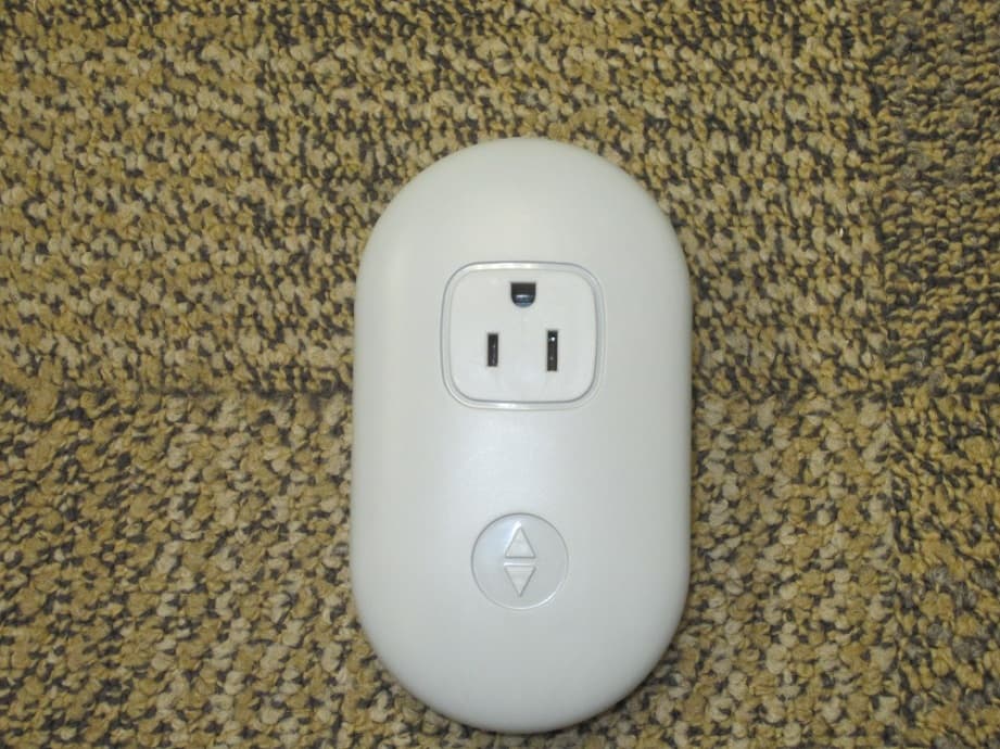
LPM-10000
May 20, 2015Smart Outlet
Equipment Class
DTS - Digital Transmission System
LPM-7000A
Feb 23, 2014Sleep monitoring and tracking system with the ability to monitor heart rate, respiration rate, and motion.
Equipment Class
DTS - Digital Transmission System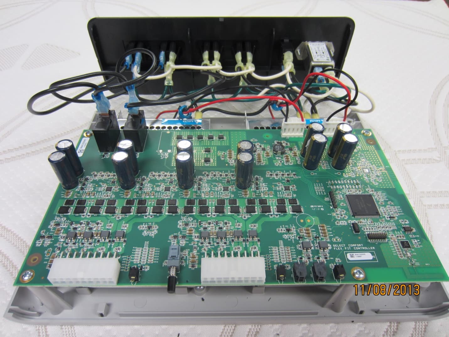
LPM-9000A
Dec 01, 2013Select Comfort Flex Fit
Equipment Class
DTS - Digital Transmission SystemLPM-6000A
Mar 21, 2013Dual Temperature Engine
Equipment Class
DXX - Part 15 Low Power Communication Device Transmitter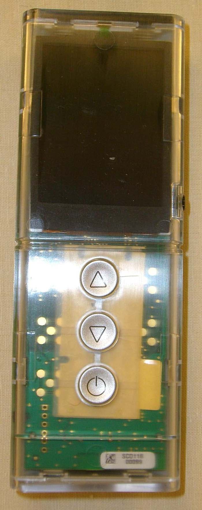
LPM-5000A
Mar 10, 2013NXT Remote
Equipment Class
DXX - Part 15 Low Power Communication Device Transmitter