LPM4000ASNAB1
Sleep Number Corporation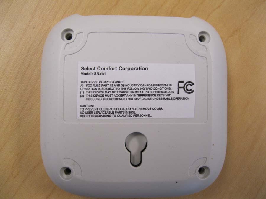
Click to zoom
Application Details
- Equipment Class
- DTS - Digital Transmission System
- Date of Grant
- Mar 08, 2011
- Application Purpose
- Original Equipment
- Date of Application
- Mar 08, 2011
- Equipment Note
- SNAB1
- Frequency Range
- 2405.00000000 - 2480.00000000
- Company
- Sleep Number Corporation
- Country
- United States
Documents & Files
Document Text
Text extracted from the exhibit documents filed with the FCC. Open a document above to read the original.
Users Manual
Before You Begin Select Number App Quick Start If you haven’t already, you will need to get the unique Identifier (UDID) for your iPhone or iPod Touch, and then download and install the Select Number App. The instructions for downloading and installing the application should have already been given to you.. System Requirements - iPhone or iPod Touch - Software Version 4.0 or later is required - Select Number App installed - WiFi turned on - WiFi router - Sleep Number bed with Corolla Pump - FlexFit+ Adjustable Base - Bridge Controller - Base Controller Overview Your Select Number App system comes with a Bridge Controller that allows your iPhone or iPod Touch to communicate with the Sleep Number bed pump via your home WiFi network. As an FlexFit+ owner, you will also recieve a Base Controller that allows your iPhone or iPod Touch to communicate with the Base motor via your home WiFi network. The following setup diagram illustrates how the various system components should be set up. Select Number App Quick Start Step 1: Unpack and check contents SELECT COMFORT Corporation *Caution Statement: Per FCC 15.21: Changes or modifications to this product not expressly approved by Select Comfort Corporation could void the user's authority to operate the equipment.. This device complies with: A) Part 15 Operation is subject to the following two conditions: 1) This device may not cause harmful interference, and 2) This device must accept any interference received Including interference that may cause undesirable operation Caution: To prevent electric shock, Do not remove cover. No user serviceable parts inside. Refer to servicing to qualified personnel. Step 2: Connecting to your home network Select Number App Quick Start The Bridge needs to connect to your home WiFi router using an Ethernet cable. A 3-foot cable has been provided for you, however longer cables can be used to give you more flexibility in positioning the Bridge. a) Make sure that the power supply is not plugged into the Bridge yet. b) Plug the Ethernet cable into an available Ethernet port on your wireless router. c) Plug the other end of the Ethernet cable into the Ethernet port on the back of the Bridge. d) Plug the power supply into the power jack on the Bridge and then plug the power cord into the wall. This will power on the Bridge. e) The blue Sleep Number icon on the Bridge will glow blue and blink, and the green and amber lights on the Ethernet port will begin to flash. f) When the blue Sleep Number icon stops flashing and stays lit, the Bridge has been successfully connected to your home network. Step 3: Connecting your iPhone or iPod Touch to your Sleep Number bed Before you can enjoy the benefits of your new Sleep Number App, you need to connect your iPhone or iPod Touch to your Sleep Number bed. This process is referred to as “binding.” a) To bind a new device, you must first unplug your Sleep Number pump from the power outlet. b) Wait 5 seconds, then plug the pump back into the power outlet. These two steps place the pump into a binding mode that lasts for 60 seconds. d) The application will automatically bind your device with your bed. e) Close the application. The app should be off before starting Step 4. Step 4: Connecting the Base Controller to your Base Motor Select Number App Quick Start The Base Controller needs to be connected between the small black RF box and the large Base Motor using the supplied Y Cable. The Y Cable has three separate connectors, one at the base (C) and two on different length cables (D,E). This will allow iPhone or iPod Touch to control your adjustable Base. a) Make sure that the power supply is not plugged into the Base Controller yet. b) Unplug the data cable from the Base Motor. This is the cable between the small black RF box and the Base Motor. c) Connect the base of the Y-Cable (C) to the data cable you just unplugged. d) Connect the short cable connector (D) to the Base Controller. e) Connect the long cable connector (E) to the Base Motor. f) ForEastern King, California King and Split King Adjustable Base beds, repeat steps a-e with the additional Base Motor and RF box. g) Plug the power supply into the power jack on the Base Controller and the power cord into the wall. h) Launch the Sleep Number App in your iPhone or iPod Touch. i) The application will automatically bind your device with your Base Controller. Step 5: Enjoy. Individualize. Sleep. You can now use your the Sleep Number App to control your Sleep Number bed. Troubleshooting Select Number App Quick Start If you are experiencing difficulties with any of these steps, first navigate to the Diagnostics page in your Sleep Number App: My Bed > The Diagnostics page will show the connection status of each of the system components. Search the troubleshooting scenarios below before pressing the ReBind buttons. My WiFi is not connected: a) Ensure that the WiFi is turned on in your iPhone or iPod Touch: Settings > WiFi > On b) Reboot your WiFi router. Unplug the power to the router > Wait 30 seconds > Plug router back in > Confirm WiFi connection on the Diagnostics page. My Bridge is not binding: a) Ensure that the Bridge is powered on. The Sleep Number icon will glow blue. b) Ensure the Bridge is connected to the WiFi router. a. Check Ethernet cable connections. b. Check that both the Green and Amber lights on the Ethernet port are lit. The Green light should be constant, the Amber light should be blinking. c) Repeat Step 2: Connecting to your home network. d) Press the ReBind button for the Bridge on the Diagnostics page. My Pump is not binding: Select Number App Quick Start a) Your Bridge may be out of range to your pump. a. Try moving the Bridge closer to the pump. b. Move the Bridge away from other electronic devices that may be causing signal interference. b) Repeat steps a and b of Step 3: Connecting your iPhone or iPod Touch to your Sleep Number bed. c) Press the ReBind button for the Pump on the Diagnostics page. My Base is n…
Text truncated - open the document above for the full version.
Cover Letter(s)
Northwest EMC TCB Compliance Opinion Rev. 12/08/09 SECF0001 Information about the Applicant Grantee (Company Name) Select Comfort Corporation FCC Contact Person Jeffery Barnum Address 9800 59th Avenue North City, State, Zip Minneapolis, MN 55442 Job Number SECF0001 Model SNab1 FCC ID LPM4000A Agent Approval Type Original Equipment Class DTS Digital Transmission System Rule Part 15C Overview Select Comfort Corporation is seeking an original grant for their model SNab1 transceiver under 47 Cfr 15.247. The FCC ID for the device is LPM4000A. The transmitter is used to control setting of the Select Comfort Corporation's adjustable foundation for their beds. Confidentiality requested for allowed files. Request is properly addressed and referenced. Short term confidentiality requested. A letter listing the applicable modular requirements was submitted. Recommendation All items have been resolved and completed to my satisfaction; therefore I recommend this application for approval. Signature Dave Tolman, TCB Committee 3/4/2011
ID Label/Location Info
Sample Label: Select Comfort Corporation Model: SNAB1 FCC ID:LPM4000A THIS DEVICE COMPLIES WITH PART 15 OF THE FCC RULES OPERATION IS SUBJECT TO THE FOLLOWING TWO CONDITIONS: (1) THIS DEVICE MAY NOT CAUSE HARMFUL INTERFERENCE, AND (2) THIS DEVICE MUST ACCEPT ANY INTERFERENCE RECEIVED INCLUDING INTERFERENCE THAT MAY CAUSE UNDESIRABLE OPERATION CAUTION: TO PREVENT ELECTRIC SHOCK, DO NOT REMOVE COVER. NO USER SERVICEABLE PARTS INSIDE. REFER TO SERVICING TO QUALIFIED PERSONNEL. Location of Label
Operational Description
Jeffrey Barnum Vice President of Manufacturing Operations Direct: (763) 551-6274 E-mail: [email protected] February 22, 2011 Federal Communications Commission Authorization and Evaluation Division 7435 Oakland Mills Road Columbia, Maryland 21046 Re: Antenna for Model Number SNab1 Applicant: Select Comfort Corporation FCC ID:LPM4000A To Whom It May Concern: The antenna for Model Number SNab1 is a board etched Omni-directional F – antenna with a gain of approximately 1 dBi. Below is a picture of the PCB with the F antenna
RF Exposure Info
Compliance with 47 CFR 15.247(i) “Systems operating under the provisions of this section shall be operated in a manner that ensures that the public is not exposed to radio frequency energy levels in excess of the Commission's guidelines. See § 1.1307(b)(1) of this chapter.” The EUT provides wireless control for an adjustable bed. It will be installed greater than 20 cm from the user’s head or torso. However, due to its low output power, there is no restriction from placing it within 20cm of the user. The maximum antenna gain is 2 dBi. The maximum peak conducted output power is 1.24 mW. The maximum peak radiated power is 2.0 mW EIRP for FCC ID: LPM4000A. The transmit frequency is 2405 to 2480MHz, therefore the EUT does not require routine SAR evaluation because it falls below the low power threshold of 60/f(GHz)mW. Please see this excerpt from KDB 447498D01 Mobile Portable RF Exposure v04, item 2)(a)(i): "a device may be used in portable exposure conditions with no restrictions on host platforms when either the source-based time-averaged output power is <=60/f(GHz)mW or all measured 1-g SAR are <0.4W.kg." The applicant’s wireless radio, FCC ID: LPM4000A, is compliant with the requirements of FCC 15.247(i).
Test Report
Select Comfort Corporation Adjustable Foundation Interface Model: SNab1 Report No. SECF0001 Report Prepared By www.nwemc.com 1-888-EMI-CERT © 2011 Northwest EMC, Inc 22975 NW Evergreen Parkway Suite 400 Hillsboro, Oregon 97124 Certificate of Test Last Date of Test: January 19, 2011 Select Comfort Corporation Adjustable Foundation Interface Model: SNab1 Emissions Test Description Specification Test Method Pass/Fail Occupied Bandwidth FCC 15.247:2011 ANSI C63.10:2009 Pass Output Power FCC 15.247:2011 ANSI C63.10:2009 Pass Band Edge Compliance FCC 15.247:2011 ANSI C63.10:2009 Pass Spurious Conducted Emissions FCC 15.247:2011 ANSI C63.10:2009 Pass Power Spectral Density FCC 15.247:2011 ANSI C63.10:2009 Pass Spurious Radiated Emissions FCC 15.247:2011 ANSI C63.10:2009 Pass AC Powerline Conducted Emissions FCC 15:207:2011 ANSI C63.10:2009 Pass Modifications made to the product See the Modifications section of this report Test Facility The measurement facility used to collect the data is located at: Northwest EMC, Inc. 9349 W Broadway Ave. Brooklyn Park, MN 55445 Phone: (763) 425-2281 Fax: (763) 424-3469 This site has been fully described in a report filed with and accepted by the FCC (Federal Communications Commission) and Industry Canada (Site filing #2834E-1). Approved By: Tim O'Shea, Operations Manager NVLAP Lab Code: 200881-0 This report must not be used to claim product certification, approval, or endorsement by NVLAP, NIST, or any agency of the federal government of the United States of America. Product compliance is the responsibility of the client, therefore the tests and equipment modes of operation represented in this report were agreed upon by the client, prior to testing. This Report may only be duplicated in its entirety. The results of this test pertain only to the sample(s) tested. The specific description is noted in each of the individual sections of the test report supporting this certificate of test. Northwest EMC Revision History Revision 06/29/09 Barometric Pressure The recorded barometric pressure has been normalized to sea level. Revision Number Description Date Page Number 00 None Accreditations and Authorizations FCC Accredited by NVLAP for performance of FCC radio, digital, and ISM device testing. Our Open Area Test Sites, certification chambers, and conducted measurement facilities have been fully described in reports filed with the FCC and accepted by the FCC in letters maintained in our files. Northwest EMC has been accredited by ANSI to ISO / IEC Guide 65 as a product certifier. We have been designated by the FCC as a Telecommunications Certification Body (TCB). This allows Northwest EMC to certify transmitters to FCC specifications in accordance with 47 CFR 2.960 and 2.962. NVLAP Northwest EMC, Inc. is accredited under the National Voluntary Laboratory Accreditation Program (NVLAP) for satisfactory compliance with the requirements of ISO/IEC 17025 for Testing Laboratories. NVLAP is administered by the National Institute of Standards and Technology (NIST), an agency of the U.S. Commerce Department. The NVLAP accreditation encompasses Electromagnetic Compatibility Testing in accordance with the European Union EMC Directive 2004/108/EC, and ANSI C63.4. Additionally, Northwest EMC is accredited by NVLAP to perform radio testing in accordance with the European Union R&TTE Directive 1999/5/EEC, the requirements of FCC, and the RSS radio standards for Industry Canada. Industry Canada Accredited by NVLAP for performance of Industry Canada RSS and ICES testing. Our Open Area Test Sites and certification chambers comply with RSS-Gen, Issue 2 and have been filed with Industry Canada and accepted. Northwest EMC has been accredited by ANSI to ISO / IEC Guide 65 as a product certifier. We have been designated by NIST and recognized by Industry Canada as a Certification Body (CB) per the APEC Mutual Recognition Arrangement (MRA). This allows Northwest EMC to certify transmitters to Industry Canada technical requirements. (Site Filing Numbers - Hillsboro: 2834D-1, 2834D-2, Sultan: 2834C-1, Irvine: 2834B-1, 2834B-2, Brooklyn Park: 2834E-1) CAB Designated by NIST and validated by the European Commission as a Conformity Assessment Body (CAB) to conduct tests and approve products to the EMC directive and transmitters to the R&TTE directive, as described in the U.S. - EU Mutual Recognition Agreement. Australia/New Zealand The National Association of Testing Authorities (NATA), Australia has been appointed by the ACA as an accreditation body to accredit test laboratories and competent bodies for EMC standards. Accredited test reports or assessments by competent bodies must carry the NATA logo. Test reports made by an overseas laboratory that has been accredited for the relevant standards by an overseas accreditation body that has a Mutual Recognition Agreement (MRA) with NATA are also accepted as technical grounds for product conformity. The report should be endorsed with the respective logo of the accreditation body (NVLAP). Accreditations and Authorizations VCCI Accepted as an Associate Member to the VCCI, Acceptance No. 564. Conducted and radiated measurement facilities have been registered in accordance with Regulations for Voluntary Control Measures, Article 8. (Registration Numbers. - Hillsboro: C-1071, R-1025, G-84, C-2687, T- 1658, and R-2318, Irvine: R-1943, G-85, C-2766, and T-1659, Sultan: R-871, G-83, C-1784, and T-1511, Brooklyn Park: R-3125, G-86, G-141, C-3464, and T-1634). BSMI Northwest EMC has been designated by NIST and validated by C-Taipei (BSMI) as a CAB to conduct tests as described in the APEC Mutual Recognition Agreement (US0017). GOST Northwest EMC, Inc. has been assessed and accredited by the Russian Certification bodies Certinform VNIINMASH, CERTINFO, SAMTES, and Federal CHEC, to perform EMC and Hygienic testing for Information Technology Products. As a result of their laboratory assessment, they will accept test results from Northwest EMC, Inc. for product…
Text truncated - open the document above for the full version.
Test Setup Photos
NORTHWEST EMC Direct Con 002.jpg Direct Con 005.jpg OCCUPIED BANDWIDTH XMit 2010.11.03 NORTHWEST EMC Direct Con 002.jpg Direct Con 005.jpg OUTPUT POWER XMit 2010.11.03 NORTHWEST EMC Direct Con 002.jpg Direct Con 005.jpg BAND EDGE COMPLIANCE XMit 2010.11.03 NORTHWEST EMC Direct Con 002.jpg Direct Con 005.jpg SPURIOUS CONDUCTED EMISSIONS XMit 2010.11.03 NORTHWEST EMC Direct Con 002.jpg Direct Con 005.jpg POWER SPECTRAL DENSITY XMit 2010.11.03 NORTHWEST EMC SE 001.jpg SE 002.jpg Spurious Radiated Emissions PSA-ESCI 2010.04.06 NORTHWEST EMC SE 004.jpg SE 005.jpg Spurious Radiated Emissions PSA-ESCI 2010.04.06 description MODES OF OPERATION Transmitting modulated signal at High Channel 2480 MHz. Transmitting modulated signal at Mid Channel 2450 MHz. Transmitting modulated signal at Low Channel 2405 MHz. POWER SETTINGS INVESTIGATED 120VAC/60Hz CONFIGURATIONS INVESTIGATED SECF0001 - 4 SAMPLE CALCULATIONS Conducted Emissions: Adjusted Level = Measured Level + Transducer Factor + Cable Attenuation Factor + External Attenuator TEST EQUIPMENT IDInterval MNC13 mo REF13 mo HGN13 mo ARF12 mo LIY12 mo MEASUREMENT BANDWIDTHS MEASUREMENT UNCERTAINTY TEST DESCRIPTION TTEH97-100K-50-720B6/28/2010 Attenuator, 20 dBSM ElectronicsSA01B-20 MN03 CablesESM Cable Corp.Conducted Cables6/8/2010 1/3/2011 1000.0 Measurements were made using the bandwidths and detectors specified. No video filter was used. 1000.0N/A 30.0 - 1000100.0 (kHz) 10.09.09.0 A measurement uncertainty estimation has been performed for each test per our internal quality document WP 342. The estimation is used to compare the measured result with its "true" or theoretically correct value. The expanded measurement uncertainty for radiated emissions measurements is less than +/- 4 dB, and for conducted emissions measurements is less than +/- 2.7 dB. Our measurement data meets or exceeds the measurement uncertainty requirements of CISPR 16-4; therefore, the test data can be compared directly to the specification limit to determine compliance. The calculations for measurement uncertainty are available upon request. 120.0120.0 0.15 - 30.0 Above 1000 Peak DataQuasi-Peak DataAverage Data 0.01 - 0.151.00.20.2 (MHz)(kHz)(kHz) Testing was performed using the mode(s) of operation and configuration(s) noted within the report. The individuals and/or the organization requesting the test provided the modes, configurations and settings used to complete the evaluation. The actual test parameters are specified in the test data, this includes items such as investigated frequency range (scanned) and test levels. The testing methods and performance specifications, as well as the test site used for the evaluation are indicated in the test data. LISNSolar Electronics9252-50-R-24-BNC8/3/2010 ReceiverRohde & SchwarzESCI3/30/2010 High Pass Filter PSA-ESCI 2010.04.06 Frequency Range DescriptionManufacturerModelLast Cal. NORTHWEST AC Powerline Conducted Emissions EMC The EUT will be powered either directly or indirectly from the AC power line. Therefore, conducted emissions measurements were made on the AC input of the EUT, or on the AC input of the device used to power the EUT. The AC power line conducted emissions were measured with the EUT operating at the lowest, the highest, and a middle channel in the operational band. The EUT was transmitting at its maximum data rate. For each mode, the spectrum was scanned from 150 kHz to 30 MHz. The test setup and procedures were in accordance with ANSI C63.10-2009. cond Work Order:Date: Project:Temperature: Job Site:Humidity:Trevor Buls.jpg Serial Number:Tested by:Trevor Buls EUT:Adjustable Foundation Interface Configuration:4 Select Comfort Corporation Attendees:Paul Mahoney 120VAC/60Hz Test SpecificationsTest Method Run #1Line:High LineExt. Attenuation:20Results Freq AmplitudeFactorAdjustedSpec. Limit Compared to Spec. Freq AmplitudeFactorAdjustedSpec. Limit Compared to Spec. (MHz) (dBuV)(dB)(dBuV)(dBuV)(dB) (MHz) (dBuV)(dB)(dBuV)(dBuV)(dB) 0.52717.620.137.756.0-18.30.52717.620.137.746.0-8.3 0.83316.220.136.356.0-19.70.83316.220.136.346.0-9.7 0.16025.020.145.165.5-20.40.16025.020.145.155.5-10.4 0.75215.220.135.356.0-20.70.75215.220.135.346.0-10.7 0.18223.320.143.464.4-21.00.18223.320.143.454.4-11.0 0.15024.920.145.066.0-21.00.15024.920.145.056.0-11.0 0.49214.820.134.956.1-21.20.49214.820.134.946.1-11.2 0.42715.820.135.957.3-21.40.42715.820.135.947.3-11.4 1.47213.820.133.956.0-22.11.47213.820.133.946.0-12.1 0.87213.820.133.956.0-22.10.87213.820.133.946.0-12.1 3.24813.520.233.756.0-22.33.24813.520.233.746.0-12.3 0.21320.520.140.663.1-22.50.21320.520.140.653.1-12.5 0.92013.020.133.156.0-22.90.92013.020.133.146.0-12.9 1.16812.920.133.056.0-23.01.16812.920.133.046.0-13.0 2.06412.820.233.056.0-23.02.06412.820.233.046.0-13.0 3.83212.820.233.056.0-23.03.83212.820.233.046.0-13.0 1.75212.720.232.956.0-23.11.75212.720.232.946.0-13.1 0.81512.720.132.856.0-23.20.81512.720.132.846.0-13.2 0.41414.020.134.157.6-23.50.41414.020.134.147.6-13.5 2.23212.320.232.556.0-23.52.23212.320.232.546.0-13.5 NORTHWEST AC Powerline Conducted Emissions EMC Peak Data - vs - Quasi Peak LimitPeak Data - vs - Average Limit PSA-ESCI 2010.04.06 Version 2010.3.17 SECF000101/19/11 None23.52°C MN037.72 3A863790Barometric Pres.:1022.7 Customer: FCC 15.207:2011ANSI C63.10:2009 EUT Power: Operating Mode: Deviations: Comments: None Transmitting modulated signal at Low Channel 2405 MHz. None Pass Peak Data - vs - Quasi Peak Limit 0 10 20 30 40 50 60 70 80 90 100 0.101.0010.00100.00 MHz dBuV Peak Data - vs - Average Limit 0 10 20 30 40 50 60 70 80 90 100 0.101.0010.00100.00 MHz dBuV cond Work Order:Date: Project:Temperature: Job Site:Humidity:Trevor Buls.jpg Serial Number:Tested by:Trevor Buls EUT:Adjustable Foundation Interface Configuration:4 Select Comfort Corporation Attendees:Paul Mahoney 120VAC/60Hz Test SpecificationsTest Method Run #3Line:NeutralExt. Attenuation:20Results Freq AmplitudeFactorAdjustedSpec. Limit Compared to Spec. Freq AmplitudeFactorAdjustedSpec. Limit …
Text truncated - open the document above for the full version.
Contact Information
Applicant
Jeff Barnum(VP of Manufacturing Operations)
Test Firm
Northwest EMC, Inc.Greg Kiemel
Technical Specifications
| # | Rule Parts | Frequency Range | Power Output |
|---|---|---|---|
| 1 | 15C | 2.40 GHz - 2.48 GHz | 1.24 mW |
Other Applications from Sleep Number Corporation
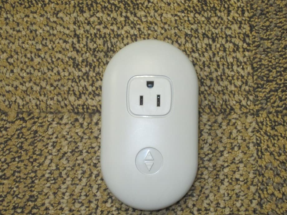
LPM-10000
May 20, 2015Smart Outlet
Equipment Class
DTS - Digital Transmission System
LPM-7000A
Feb 23, 2014Sleep monitoring and tracking system with the ability to monitor heart rate, respiration rate, and motion.
Equipment Class
DTS - Digital Transmission System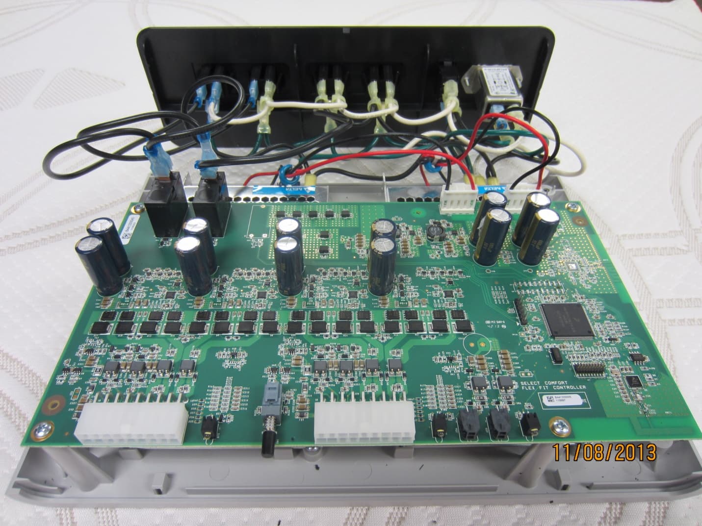
LPM-9000A
Dec 01, 2013Select Comfort Flex Fit
Equipment Class
DTS - Digital Transmission SystemLPM-6000A
Mar 21, 2013Dual Temperature Engine
Equipment Class
DXX - Part 15 Low Power Communication Device Transmitter
LPM-5000A
Mar 10, 2013NXT Remote
Equipment Class
DXX - Part 15 Low Power Communication Device Transmitter