MES433L7GPCSmart Card Reader
Thales DIS France SAS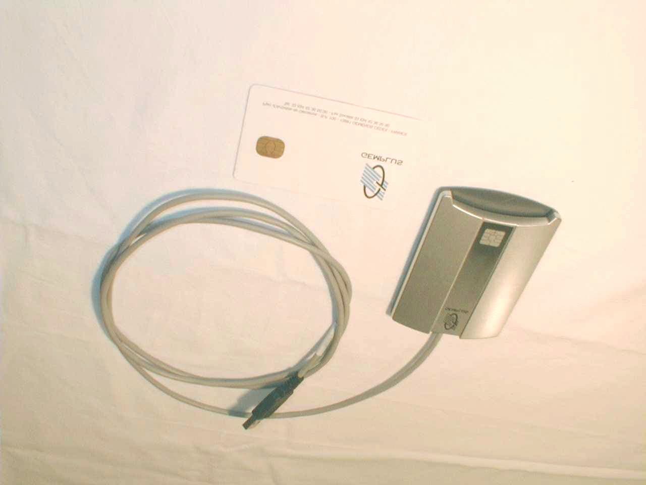
Click to zoom
Application Details
- Equipment Class
- JBP - Part 15 Class B Computing Device Peripheral
- Date of Grant
- Nov 19, 2001
- Application Purpose
- Original Equipment
- Date of Application
- Nov 19, 2001
- Equipment Note
- Smart Card Reader
- Company
- Thales DIS France SAS
- Country
- France
Documents & Files
Document Text
Text extracted from the exhibit documents filed with the FCC. Open a document above to read the original.
Users Manual
FCC ID: MES433L7GPC 1 USER MANUAL This is a copy of the page where the FCC statement is included; This statement is supplied in the package of the product. This device complies with part 15 of the FCC rules. Operation is subject to the following two conditions : (1) This device may not cause harmful interference, and (2) this device must accept any interference received, including interference that may cause undesired operation. Regulatory Information Notice for the USA: FCC Statement Federal Communications Commission (FCC) Radio Frequency Interference Statement (USA Only) This equipment has been tested and found to comply with the limits for a class B digital device, pursuant to Part 15 of FCC Rules. These limits are designed to provide reasonable protections against harmful interference in a residential installation. This equipment generates, uses and can radiate radio frequency energy and, if not installed and used in accordance with the instructions, may cause harmful interference to radio communications. However, there is no guarantee that interference will not occur in a particular installation. If this equipment does cause harmful interference to radio or television reception, which can be determined by turning the equipment off and on, the user is encouraged to try one of more of the following measures: ‡ Relocate the radio or television antenna. ‡ Plug the equipment away from the radio or television. ‡ Plug the equipment into a different electrical outlet, so that the equipment and the radio or television are on separate electrical circuits. ‡ Make sure that all your peripheral devices ar also FCC Class B certified. ‡ Make sure you use only shielded cables to connect peripheral devices to your equipment. ‡ Consult your equipment dealer, or an experienced radio / television technician for help. WARNING: The system verification tests were conducted with GEMPLUS supported peripheral devices. Cables used with this equipment must be properly shielded to comply with the requirements of the FCC. Changes or modifications not expressly approved by GEMPLUS could void the user's authority to operate the equipment.
Block Diagram
FCC ID: MES433L7GPC Page 1/1 1 BLOCK DIAGRAM OF EQUIPMENT 1.1 Clock list of GemPC433-SL7 and GemPC433-SW7 products Crystal oscillator : 4 MHz Data Link (on USB): 12 MHz 1.2 Block diagram of GemPC433-SL7 and GemPC433-SW7 products
External Photos
FCC ID: MES433L7GPC Page 1/4 1 EXTRERNAL PHOTOS OF TESTED EUT (GEMPC433-SL7) General view, smart card inserted General view, smart card removed FCC ID: MES433L7GPC Page 2/4 General view, smart card removed Bottom view Bottom view Top view FCC ID: MES433L7GPC Page 3/4 2 EXTRERNAL PHOTOS OF TESTED EUT (GEMPC433-SW7) General view, smart card inserted General view, smart card removed FCC ID: MES433L7GPC Page 4/4 General view, smart card removed Bottom view Top viewBottom view
ID Label/Location Info
FCC ID: MES433L7GPC 1 PRODUCT LABELING 1.1 FCC ID Label This is a photo of the label stuck on the product. The label materiel is 50μm metal polyester adhesive. This adhesive is permanent . (Size : 21.6mm x 49.1mm) M/N name of the reader: Gemplus P/N: Gemplus logo:Gemcore logo: GemPC433-SL7HPW106513 A0YESYES GemPC433-SW7HPW106679 A0YESYES FCC ID: MES433L7GPC 1.2 Location of label on EUT Label is stuck on the bottom face of the product (see pictures). GemPC433-SL7GemPC433-SW7 Label will be at that location
Internal Photos
FCC ID: MES433L7GPC Page 1/6 1 INTERNAL PHOTOS OF TESTED EUT (GEMPC433-SL7) Internal view, Box opened Internal view, Box opened Without internal board FCC ID: MES433L7GPC Page 2/6 Internal board, Component side Internal board, Component side, smart card connector removed (Component and copper on the same face, single layer) FCC ID: MES433L7GPC Page 3/6 Internal board, Foil side (No copper on this side) FCC ID: MES433L7GPC Page 4/6 2 INTERNAL PHOTOS OF TESTED EUT (GEMPC433-SW7) Internal view, Box opened Internal view, Box opened Without internal board FCC ID: MES433L7GPC Page 5/6 Internal board, Component side Internal board, Component side, smart card connector removed (Component and copper on the same face, single layer) Remark: PCB of the GemPC433-SW7 is the same than the GemPC433-SL7 (Edges are cut and the led is removed) FCC ID: MES433L7GPC Page 6/6 Internal board, Foil side (No copper on this side) 3 PHOTOS OF THE SMART CARD
Operational Description
FCC ID: MES433L7GPC Page 1/5 1 GENERAL INFORMATION 1.1 Product description The GemPC433-SL7 and GemPC433-SW7 devices are a smart card readers connected to a Personal Computer. Smart cards which can be used with the GemPC433-SL7 and -SW7 readers are ISO7816-1/2/3/4 compatible smart cards. It is introduced in the reader, and the Personal Computer manages applications; Typical applications are: - Computer access control - Electronic commerce - Home banking facilities - E-purse facilities - Electronic smart card personalization - Development of smart card application software - Others... The GemPC433-SL7 and SW7 reader are connected to the USB Type A slot for communication with the Personal Computer, and is also powered, by USB port.. The GemPC433-SL7 and SW7 are products developed by the Gemplus company; theirs part numbers are HWP106513 A0 (-SL7) and HPW106679 A0(-SW7). For more information, see product's data sheet at section 1.6. GemPC433-SL7 and GemPC433-SW7 are similar products with the same architecture. The GemPC433-SL7 has an added LED connected to the PCB, which is not present in the GemPC433-SW7. (See detailed internal pictures of products). Main difference between GemPC433-SL7 and GemPC433-SW7 is summarized in the following table : GemPC433-SL7GemPC433-SW7 With LEDNo LED 1.2 Related Submittal(s) / Grant(s) All host equipment used in the test configuration are FCC granted, when relevant. FCC ID: MES433L7GPC Page 2/5 1.3 Tested System Details The FCC IDs for all equipment, plus description of all cables used in the tested system (including inserted cards, which have grants) are : Trade Mark – Model Number (Serial number) FCC IDDescriptionCable description GemPC433-SL7 PN: HWP106513 A0* (sn: F0190000004) MES433L7GPCSmart card readerShielded cable attached to product GemPC433-SW7 PN: HWP106679 A0* (sn: F0190000000) MES433L7GPCSmart card readerShielded cable attached to product GEMPLUSNoneSmart cardnone Laptop Dell Latitude CPiAD400XTB series PN: 0006692D-12800-03T-3722 (sn: VSRW6) with AC adapter Dell P/N: 0009364U Dec. Of ConfPersonal computerAll data cables are shielded Power cable unshielded HEWLETT PACKARD D2846 (sn: JP74001000) Dec. Of Conf.21" color monitorShielded video cable with two integrated ferrites COMPAQ (Logitech) M/N: M-S48a (sn: 187104-001) JNZ201213MouseShielded cable HEWLETT PACKARD C2106A (sn: 3110S58792) B94C2106XSerial printerHP 24542G shielded serial cable HEWLETT PACKARD C6410A (sn: MY9761915T) Dec. Of Conf.Parallel printerHP C2950A shielded parallel cable TELEX (sn: 700.373.000A) NoneMicrophoneShielded cable LABTEC LT100 (sn: none) NoneHeadsetShielded cable *Equipment Under Test 1.4 Test Methodology Both conducted and radiated testing were performed according to the procedures in ANSI C63.4-1992, CISPR22-1993/A1:1995/A2:1996 and EN55022:1994/A1:1995/A2:1997. Radiated testing was performed at an antenna to EUT distance of 10 meters. During testing, all equipment’s and cables were moved relative to each other in order to identify the worst case set-up. In order to determinate which setup produce the maximum emission (during a pre-scan evaluation), SL7 and SW7 have been tested. The operating mode which produce the highest level emission is SL7. Consequently, all test results contained in this test report are from the SL7. 1.5 Test facility Tests have been performed on April 26 th , 2001. The test facility used to collect the radiated and conducted data is the SMEE Actions Mesures facility, located ZI des Blanchisseries, 38500 VOIRON, France. This test facility has been fully described in a report and accepted by FCC as compliant with the radiated and AC line conducted test site criteria in ANSI C63.4-1992 in a letter dated August 04, 1999 (registration number 94821). This test facility has also been accredited by COFRAC (French accreditation authority for European union test lab accreditation organization), accreditation number 1-0844 as compliant with test site criteria and competence in EN55022/CISPR22 norms for 89/336/EEC European EMC Directive application. All pertinent data for this test facility remains unchanged. FCC ID: MES433L7GPC Page 3/5 1.6 Data sheet of the product (technical data also valid for GemPC433-SW7) GemPC433-SL7 Gemplus' USB Smart Card Reader: A highly accessible, highly convenient solution. This compact card reader, designed to plug into a PC environment, is the ultimate smart card peripheral for a PC. It is also very simple to use and install. The user needs no technical knowledge. If you need electronic commerce, home banking or e-purse facilities, secure computer access or any of a multitude of other applications, the GemPC433-SL7 is the smartest answer. For the first time, a solution is available that offers impressive possibilities at an exceptional price. Small is beautiful At a mere 70 x 98 x 15 mm, the GemPC433-SL7 will handle the card interface, while your computer supports and manages the applications. Compatible with all major computers and operating systems, the GemPC433-SL7 is powered from any USB type A slot available, free of the constraints associated with other power-source options. It will open up many possibilities, including: • computer-access control, • electronic commerce, • home banking facilities, • e-purse facilities, • electronic smart-card personalization, • development of smart-card application software, • lots of other interesting or entertaining things. FCC ID: MES433L7GPC Page 4/5 Years of Gemplus technological experience, now available to all The GemPC433-SL7 is based on Gemplus’ GemCore ® hardware and firmware, which means it can handle all types of ISO7816- compatible smart cards without compatibility problems. It is user-friendly, and operating or using it requires no technical expertise. The GemPC433-SL7 will happily blend with all main environments (Windows ® 98, Windows ® 2000, etc.), all types of card, and most makes of computer. It will readily adapt to new smart-card services, as they become availa…
Text truncated - open the document above for the full version.
Test Report
FCC ID: MES433L7GPC Page 1/7 1 TEST REPORT 1.1 System test configuration 1.1.1 Justification GemPC433-SL7 and GemPC433-SW7 are similar products with the same architecture. The GemPC433-SL7 has an added LED connected to the PCB, which is not present in the GemPC433-SW7. (See detailed internal pictures of products). The 10-meters open site measurement was performed with the GemPC433-SL7. It was found during the 3- meters pre-characterization to have highest radiated emission level than the GemPC433-SW7. The system was configured for testing in a typical fashion (as a customer would normally use it). A typical smart card was introduced in the GemPC433-SL7 (or -SW7) reader, which was itself connected to a personal computer. It has been tested with a Dell Latitude Personal computer laptop. Each ports of the Personal Computer were loaded with a typical peripheral device. 1.1.2 EUT Exercise software The EUT exercise program (Apitest V1.0, running in loop under Windows 98) used during radiated and conducted testing was designed to exercise the GemPC433-SL7 (or -SW7) reader in a manner similar to a typical use . 1.1.3 Special accessories The cable which connect the GemPC433 reader to USB port of the Personal Computer, is shielded and attached to the GemPC433. The smart card used in the GemPC433 is a ISO 7816 type. Figure #1, shows the installation of the GemPC433. All interfaces cables used for compliance testing are shielded as normally supplied. All these cables are normally recommended to be used with the Personal Computer. 1.1.4 Equipment modifications No equipment modification has been necessary during testing to achieve compliance to Class B levels. The unit tested was representative to a production unit. 1.1.5 Configuration of tested system Fig #1 μphone HP C2106A PrinterHP C6410A Printer Monitor D2846 PC Dell Mouse GemPC433-SL7 Smart card reader LT100 headset 80 cm FCC ID: MES433L7GPC Page 2/7 1.2 Conducted emission data 1.2.1 Test procedure The product has been tested according to ANSI C63.4-1992, CISPR22-1993/A1:1995/A2:1996 and EN55022:1994/A1:1995/A2:1997. The product has been tested with 110V / 60Hz power line voltage and compared to the CISPR22 Class B limits. Measurement bandwidth was 9kHz from 150 kHz to 30 MHz. Measurement was initially made with an HP-8591EM Spectrum Analyzer in peak mode. This was followed by a Quasi-Peak, i.e. CISPR measurement with the Rohde & Schwarz ESH3 receiver for any strong signal. If the average limit is met when using a Quasi-Peak detector, the EUT shall be deemed to meet both limits and measurement with the average detector is unnecessary. The Peak data are shown on the following plots. Quasi-Peak and Average measurements are detailed in a table with frequencies and levels measured. Interconnecting cables and equipment's were moved to position that maximized emission. A summary of the worst case emissions found in all test configurations and modes is shown on the following page. Test equipment : HP 8591EM Spectrum Analyzer Rhode & Schwarz ESH3 Receiver EMCO 3810/2SH LISN N°1 TELEMETER NNB-2/16L LISN N°2 FCC ID: MES433L7GPC Page 3/7 1.2.2 Neutral conducted emission data on GemPC433-SL7 Freq.PeakQ-PeakQP limit QP delta AverageAVG Limit AVG Delta Num. [MHz][dBμV][dBμV][dBμV] [dB] [dBμV][dBμV] [dB] 10.18055.9749.8764.5-14.537.7954.5-16.7 20.25045.9439.3761.7-22.318.1551.7-33.5 30.35039.8731.5758.9-27.318.7848.9-30.1 42.64041.6636.9756.0-19.029.3146.0-16.7 54.93039.5535.0756.0-21.029.2846.0-16.7 65.78040.9336.0660.0-24.029.6250.0-20.4 FCC ID: MES433L7GPC Page 4/7 1.2.3 Line conducted emission data on GemPC430-SL7 Freq.PeakQ-PeakQP limit QP delta AverageAVG Limit AVG Delta Num. [MHz][dBμV][dBμV][dBμV] [dB] [dBμV][dBμV] [dB] 10.18055.9248.5864.5-16.134.9254.5-19.6 20.22048.8942.3162.8-20.519.0352.8-33.8 30.29044.7437.3760.5-23.127.2650.5-23.2 40.37038.0431.4458.5-27.125.8548.5-22.6 53.3640.1035.5356.0-20.529.1646.0-16.8 64.5839.0735.3156.0-20.728.4646.0-17.5 75.4841.1836.9160.0-23.129.9150.0-20.1 FCC ID: MES433L7GPC Page 5/7 1.3 Radiated emission data 1.3.1 Test Procedure The product has been tested according to ANSI C63.4-1992, CISPR22-1993/A1:1995/A2:1996 and EN55022:1994/A1:1995/A2:1997. The product has been tested with 230V / 50Hz power line voltage, at a distance of 10 meters from the antenna and compared to the CISPR 22 Class B limits. Measurement bandwidth was 120 kHz from 30 MHz to 1 GHz. Antenna height search was performed from 1m to 4m for both horizontal and vertical polarization. Continuous linear turntable azimuth search was performed with 360 degrees range. Interconnecting cables and equipment's were moved to position that maximized emission. A summary of the worst case emissions found in all test configurations and modes is shown on the following page. Test Equipment: HP-8574A E.M.I Receiver (HP-8568B Analyzer + HP-85650 Quasi-Peak adapter + HP-85685A RF Preselector). EMCO 3104C Biconical Antenna & EMCO 3146 Log Periodic Antenna EMCO-1050, 6 meters height antenna mast & EMCO-1060, 3 meters diameter Turntable. FCC ID: MES433L7GPC Page 6/7 1.3.2 Radiated emission data Graph example - 30-1000MHz Final result 30-1000 MHz Frequency (MHz) QPeak Lmt (dBμV/m) QPeak (dBμV/m) QPeak-Lmt (dB) Angle (deg) PolHgt (cm) Tot Corr (dB) Comments 33.27630.027.0-3.0254V10912.4 120.00730.020.0-10.0210V35917.1 127.99330.020.3-9.7269H37815.2 160.01530.023.6-6.4248H38617.4 192.00230.026.2-3.9349H39319.5 199.99930.023.3-6.7316H24420.0 333.06737.025.4-11.6247H27418.1 466.30837.031.4-5.624H19320.7 528.03637.027.0-10.1336H20522.1 599.55337.029.7-7.3183H15923.8 FCC ID: MES433L7GPC Page 7/7 1.3.3 Field Strength Calculation The field strength is calculated by adding the Antenna Factor and Cable Factor, and subtracting the Amplifier Gain (if any) from the measured reading. The basic equation with a sample calculation is as follow : FS = RA + AF + CF – AG WhereFS = Field Strength RA = Receiver Amplitude AF = Antenna Factor CF = Cable Factor AG = Amplifier Gain Assume a receiv…
Text truncated - open the document above for the full version.
Test Setup Photos
FCC ID: MES433L7GPC Page 1/2 1 CONDUCTED AND RADIATED MEASUREMENT PHOTOS 1.1 Conducted emissions Front view of the setupRear view of the setup Detailed view of EUT with the USB cable Detailed view of PC with its USB port FCC ID: MES433L7GPC Page 2/2 1.2 Radiated emission Front View of the setupRear view of the setup Detailed view of EUT with the USB cable Detailed view of PC with its USB port
Contact Information
Applicant
Jean-Cristophe RUSSO(RD Hardware Manager)
Test Firm
LCIE Sud-EstJacques Lorquin
Technical Specifications
| # | Rule Parts | Frequency Range | Power Output |
|---|---|---|---|
| 1 | 15B | - | - |
Other Applications from Thales DIS France SAS

MES-SWYSPINPAD
Sep 25, 2023Smart Card Reader USB & Bluetooth
Equipment Class
DTS - Digital Transmission System
MESIDBCT40
Jul 10, 2012Smart Card Reader
Equipment Class
JBP - Part 15 Class B Computing Device Peripheral
MESPROXDUB
Jan 16, 2011RFID Tag Reader
Equipment Class
DXX - Part 15 Low Power Communication Device Transmitter
MESPROXDU
Feb 24, 2010Card Reader
Equipment Class
JBP - Part 15 Class B Computing Device Peripheral
MESPROXU
Sep 12, 2006Tag Reader
Equipment Class
DXX - Part 15 Low Power Communication Device Transmitter