MES680SGELContactless Smart Card Reader
Thales DIS France SAS
Click to zoom
Application Details
- Equipment Class
- DXX - Part 15 Low Power Communication Device Transmitter
- Date of Grant
- Oct 30, 2000
- Application Purpose
- Original Equipment
- Date of Application
- Oct 05, 2000
- Equipment Note
- Contactless Smart Card Reader
- Frequency Range
- 13.56000000 - 13.56000000
- Company
- Thales DIS France SAS
- Country
- France
Documents & Files
Document Text
Text extracted from the exhibit documents filed with the FCC. Open a document above to read the original.
Attestation Statements
FCC ID: MES680SGEL 1 USER MANUAL This is a copy of the page where the FCC statement is included : Regulatory Information Notice for the USA: FCC State me nt Federal Communications Commission (FCC) Radio Frequency Interference Statement (USA Only) This equipment has been tested and found to comply with the limits for a class B digital device, pursuant to Part 15 of FCC Rules. These limits are designed to provide reasonable protections against harmful interference in a residential installation. This eq uip me nt ge nerates, uses and ca n radiate radio frequenc y e ner gy and, i f not installed and used in accordance with the instructions, may cause harmful interference to radio communications. However, there is no guarantee that interference will not occur in a particular installation. If this equipment does cause harmful interference to radio or television reception, which can be determined by turning the equipment off and on, the user is encouraged to try one of more of the following measures: ! Relocate the radio or television antenna. ! Plug the equipment away from the radio or television. ! Plug the equipment into a different electrical outlet, so that the equipment and the radio or television are on separate electrical circuits. ! Make sure that all your peripheral devices are also FCC Class B certified. ! Make sure you use only shielded cables to connect peripheral devices to your equipment. ! Consult your equipment dealer, or an experienced radio / television technician for help. WA RN ING: The system verification tests were conducted with GEMPLUS supported peripheral devices and GEMPLUS shielded cables, such as those you received with your system. Cables used with this equipment must be properly shielded to comply with the requirements of the FCC. Changes or modifications not expressly approved by GEMPLUS could void the user's authority to operate the equipment.
Block Diagram
FCC ID: MES680SGEL 1 BLOCK DIAGRAM(S) OF EQUIPMENT 1.1 Clock list of GemEasyLink 680SP product Crystal: 14.74 MHz 13.56 MHz 1.2 Block diagram Alimentation 5v 7v à 12v Liaison Série RS232 Liaison Série RS485 2 fils / 4 fils Liaison Série Wiegand Config 2/4 fils Rx/Tx 80C524 D0/D1 14.74 MHz Alimentation RAM ASIC P ile Capa EEPROM Série 13.56 MHz ASIC MIKRON Oscillateur RecepteurEmetteur Antenne Ferrite 5 x 7 cm Driver RS485 H.Z Led Bicolore Vers GCI682 ou Vers Mini 682 Liaison Série RS232 TTL 1.3 Pulse width and PRF The PRF of the device is 106KHz. The width of the pulse is between 2 and 3 μs. The following show the kind of signal interface (issue from ISO 14443, Art 7) and the kind of coding (issue from the manufacturer):
Cover Letter(s)
FCC ID: MES680SGEL 1 COVER LETTER GEMPLUS – GemEasyLink 680S (ex Micro680) FCC ID: MES680SGEL September 28, 2000 This report concerns : Original Grant ___ X ____Class II change __________ SubPart C certification ___ X ____ *Class A verification _______Class I change _______ Equipment type : Radio remote control system – transmitter Request issue of grant : _ X _Immediately upon completion of review ___Defer grant per 47 CFR 0.457(d)(1)(ii) until ____ date _____. Company Name agrees to notify the Commission by _____date_____ of the intended date of announcement of the product so that the grant can be issued on that date. Confidentiality of grant : ___Applicant requests the existence of this grant to be kept confidential until ____date____. The announcement of this product before this date via freedom of information would be detrimental to Company Name, and therefore must be considered a business secret. Public announcement of this product will not be made prior to this date. (Max. 60 days after grant issued). Li mi ts used : (check one) CISPR 22 _______ ___________ Part 15 _______ X ___________ Measurement procedure used is ANSI C63.4-1992 unless another is specified. Other test procedure : ____________________________________________________ Application for verificationApplicant for this device Prepared by : Frank HAMELIN SMEE Actions Mesures ZI des Blanchisseries 38500 VOIRON – France Ph. : 33 4 76 65 76 50 Fax : 33 4 76 66 18 30 e-mail : [email protected] Pierre André COLLET Ge mplus Voie Antiope Athelia III 13705 LA CIOTAT CEDEX 8 – France Ph. : 33 4 42 36 62 60 Fax : 33 4 42 36 62 98 e-mail: [email protected] *Not to be filed with Equipment Authorization Branch of FCC unless requested Report format prepared by the Information Technology Industry Council (ITI) ESC-5 and reviewed by FCC staff in 1994
External Photos
FCC ID: MES680SGEL 1 EXTERNAL PHOTOS OF TESTED EUT Ge ne ral vie w, Uppe r face General view, Bottom face
ID Label/Location Info
FCC ID: MES680SGEL 1 PRODUCT LABELING 1.1 FCC ID Label This is the copy of the label stuck on the product (Size in mm) 1.2 Location of label on EUT Label is stuck on the bottom face of the product (see drawing).
Internal Photos
FCC ID: MES680SGEL 1 INTERNAL PHOTOS OF TESTED EUT 1 – Internal view, cover removed 2 – Internal boards assembling FCC ID: MES680SGEL 3 – Upper board, component side4 – Upper board, foil side FCC ID: MES680SGEL 5 – A nte nna boa rd, f i rst side6 – A nte nna boa rd, se cond s i de FCC ID: MES680SGEL 7 – Separation sheet, component side 8 – Separation sheet, antenna side
Operational Description
FCC ID: MES680SGEL 1 GENERAL INFORMATION 1.1 Product description The GemEasyLink 680S is a contact less card reader connected to a Personal Computer. It is a serial interface reader for GemEasy 8000 cards, and other Mifare family product. The GemEasyLink 680S reader uses the coupler's RF output to radiate the magnetic field and power up the GemEasy 8000 cards. The signal is modulated by the coupler to communicate commands to the GemEasy8000. The antenna also receives modulation from the GemEasy8000 acting as a field disturbing device. This signal is then delivered to the coupler. The GemEasyLink 680S reader can communicate to the Personal Computer via the RS232 serial port. The antennas (PCB loop antennas) are tuned in the factory at 13.56 MHz with the appropriate impedance value (50 +- 10%), dephasing (0°+- 10°) and Q factor. The PCB layout and component quality level ensure the necessary stability over the entire temperature range. The GemEasyLink 680S reader is powered by an external 5Vdc power supply. The GemEasyLink 680S is a product developed by the Gemplus company; Its previous name was GemAirLink Micro-P or Micro 680, that's why in this file could appear GemAirLink Micro-P or Micro 680 instead of GemEasyLink 680S For more information, see product's data sheet at section 1.6. 1.2 Related Submittal(s) / Grant(s) All host equipment used in the test configuration are FCC granted, when relevant. 1.3 Tested System Details The FCC IDs for all equipment, plus description of all cables used in the tested system are : Tra de Ma rk – Mo de l Numbe r (Se rial numbe r) FCC IDDe scri ptio nCa ble de scri ptio n GEMPLUS GemEasyLink 680S (ex- GemAirLink Micro-P)* (sn: M9908010420) MES680SGELContactless smart card readerShielded cable attached to product Proxibus CMP201noneContactless Smart cardnone HEWLETT PACKARD Vectra 515 series D4136A (sn: FR62365527) B94VECTRA500TPersonal computerAll data cables are shielded Power cable unshielded HEWLETT PACKARD D2846A (sn JP93143078) Doc. Of Conf.21" color monitorShielded video cable HEWLETT PACKARD C4734-60101 (sn: M97060565) GYUR38SKKeyboardShielded cable HEWLETT PACKARD C3751B (sn: LZA61209812) DZL210582MouseShielded cable HEWLETT PACKARD 7475A (sn: 2807L77281) BSD4TE7475ASerial plotterHP 24542G shielded serial cable HEWLETT PACKARD C2106A (sn: 3041S18664) Doc. Of Conf.Parallel printerHP 24542D shielded parallel cable *Equipment Under Test FCC ID: MES680SGEL 1.4 Test Methodology Both conducted and radiated testing were performed according to the procedures in ANSI C63.4-1992, CISPR22-1993/A1:1995/A2:1996 and EN55022:1994/A1:1995/A2:1997. Radiated testing was performed at an antenna to EUT distance of 10 meters. During testing, all equipment’s and cables were moved relative to each other in order to identify the worst case set-up. 1.5 Test facility Tests have been performed on March 13th, 2000. The test facility used to collect the radiated and conducted data is the SMEE Actions Mesures facility, located ZI des Blanchisseries, 38500 VOIRON, France. This test facility has been fully described in a report and accepted by FCC as compliant with the radiated and AC line conducted test site criteria in ANSI C63.4-1992 in a letter dated August 04, 1999 (registration number 94821). This test facility has also been accredited by COFRAC (French accreditation authority for European union test lab accreditation organization), accreditation number 1-0844 as compliant with test site criteria and competence in EN55022/CISPR22 norms for 89/336/EEC European EMC Directive application. All pertinent data for this test facility remains unchanged. 1.6 Data sheet of the product GemEasyLink 680S (ex Micro680)- Product Sheet Very compact and convenient short-range coupler The processing features of this coupler are equivalent to those of the GCI680. An integrated antenna fitted with ferrite allows normal operation. The GemEasyLink 680S is a serial interface reader for GemEasy8000 and other Mifare ® family products, including GemFlash300 for the future release of the operating system. Typical operating distance with GemEasy8000 type contactless cards is 25 mm. The GemEasyLink 680S is available in other versions (derived products): - GemEasyLink 680SP : GemEasyLink 680S in a plastic housing for desktop applications. - GemEasyLink 680SL : this reader is a GemEasyLink 680S with a RS232 interface only. High-Level Operating System The GemEasylink 680S, like the GCI680, is microprocessor controlled and runs ROS680 firmware. This offers easy interface with applications through ISO 7816-4 APDU format commands. ROS680 has combined commands allowing an advanced sequence of elementary actions to be executed (e.g., authentication and reading or writing of several blocks on a single sector). FCC ID: MES680SGEL GemEasyLink 680S benefits from ROS680 upgrades with support for advanced commands (backup management and withdrawal management for electronic purse applications). This version of operating system supports the following cards: • GemEasy8000 • GemEasy300 The capabilities of the ROS680 significantly reduce transaction processing time and improve application efficiency. Modularity for Greater Potential The Micro680 has a modular design, allowing various options to be implemented. It can even be used as a short range active antenna driven by a GCI680 or a GemEasyLink 680S. Technical specifications: Dimensions 50 x 70 x 22 mm Power supply 7 to 12 VDC - max 120 mA (in working state) Operating range GemEasy8000: 0 to 25 mm MA8000: 0 to 15 mm Antenna Built-in ferrite antenna allowing metal mounting operation Connectors • Power supply • RS485/RS232 • Battery • Active antenna • Wiegand • TTL • Backup capacitor • Cable shield • EMC compliance Fully compliant with CE regulations Host interface RS232, RS485, TTL, Wiegand (except version 1.03) Baud rate 1.2 to 76.8 kbaud User interface Monitoring LED
Test Report
FCC ID: MES680SGEL 1 TEST REPORT 1.1 System test configuration 1.1.1 Justification The system was configured for testing in a typical fashion (as a customer would normally use it). A typical smart card was presented to the GemEasyLink 680SP contactless reader, which was itself connected to a personal computer. It has been tested with a Hewlett Packard Vectra 515series D4136A Personal computer. Each ports of the Personal Computer were loaded with a typical peripheral device. 1.1.2 EUT Exercise software The EUT exercise program (68X80.exe running under DOS) used during radiated and conducted testing was designed to exercise the GemEasyLink 680SP contactless reader in a manner similar to a typical use (reading the contactless smart card in loop) 1.1.3 Special accessories The cable used to connect the GemEasyLink 680SP contactless reader, to RS232 ports of the Personal Computer is shielded and attached to the product. It is connected to Com 1. The smart card used with the GemEasyLink 680SP contactless reader, is a Contactless Smart Card Proxibus CMP 201, manufactured by GEMPLUS. The Power supply block used to power the GemAirLinkMicro-P contactless reader, is a COMATEL ref 49199 mod: AL.0030090.1S block w hen used with 230V/50Hz, and a HITRON mod: HER-57-312 block when used with 120V/60Hz. As shown in Figure#1, all interfaces cables used for compliance testing are shielded as normally supplied. All these cables are normally recommended to be used with the Personal Computer. 1.1.4 Equipment modifications In order to comply FCC Part 15, Subpart C, a common mode ferrite has been set on serial cable, at 3cm of the connector, PC side (consequently, installation guide has been modified). The unit tested was representative to a production unit. 1.1.5 Configuration of tested system HP C2106A Printer HP 7475A plotter Mo nitor D2846A PC Ve ctr a 515 Series Mo use Keyboard GemEasyLink 680S Smart card FCC ID: MES680SGEL 1.2 Conducted emission data 1.2.1 Test procedure The product has been tested according to ANSI C63.4-1992 and FCC PART15, Subpart C, Section 15.207. The product has been tested with 120V / 60Hz power line voltage and compared to the FCC PART15, Subpart C, Section 15.207 limits. Measurement bandwidth was 9KHz from 450 KHz to 30 MHz. Measurement was initially made with an HP-8591EM Spectrum Analyzer in peak mode. This was followed by a Quasi-Peak, i.e. CISPR measurement with the Rohde & Schwarz ESH3 receiver for any strong signal. An Average measure has also been performed on peak exceeding the limit of 250μV. The Peak data are show n on the following plots. Quasi-Peak and Average measurements are detailed in a table with frequencies and levels measured. Interconnecting cables and equipment's were moved to position that maximized emission. A summary of the worst case emissions found in all test configurations and modes is shown on the following page. The13.56 MHz frequency, which is the fundamental frequency, exceeds the level when tested in normal configuration. In order to show that the product’s electronic isn’t the cause, we had performed an other test, with the product wrapped up in a conductive aluminium foil (the antenna of the product is integrated in the board, and cannot be replaced by a dummy load). In this configuration, results are FCC compliant; Graphs are shown hereafter. Test equipment : HP 8591EM Spectrum Analyzer Rhode & Schwarz ESH3 Receiver EMCO 3810/2SH LISN N°1 TELEMETER NNB-2/16L LISN N°2 FCC ID: MES680SGEL 1.2.2 Neutral conducted emission data on GemEasyLink 680SP contactless reader Freq.PeakQ-PeakQP limitQP deltaAverage Num. [MHz][dBμV][dBμV][dBμV][dBμV][dBμV] 112,5338,0136,7248,00 -11,28 213,5769,7169,5348,00 21,53 68,15 314,3337,2735,5148,00 -12,49 416,0134,2533,0948,00 -14,91 527,1238,3937,7348,00 -10,27 628,2033,4432,3248,00 -15,68 728,6543,3442,8348,00 -5,17 FCC ID: MES680SGEL 1.2.3 Line conducted emission data on GemEasyLink 680SP contactless reader Freq.PeakQ-PeakQP limitQP deltaAverage Num. [MHz][dBμV][dBμV][dBμV][dBμV][dBμV] 112,5339,8638,1848,00-9,82 213,5769,8669,6648,0021,6668,41 314,3338,1135,7048,00-12,3 416,0036,1634,0048,00-14 527,1240,3838,8548,00-9,15 628,2135,9534,1748,00-13,83 728,6544,5143,5448,00-4,46 FCC ID: MES680SGEL 1.2.4 Neutral conducted emission data on GemEasyLink 680SP contactless reader The product is wrapped up in a conductive aluminium foil 1.2.5 Line conducted emission data on GemEasyLink 680SP contactless reader The product is wrapped up in a conductive aluminium foil FCC ID: MES680SGEL 1.3 RADIATED EMISSION DATA 1.3.1 Test Procedure (15.225) The product has been tested according to ANSI C63.4-1992 and FCC PART15, Subpart C, Section 15.225. The product has been tested with 230V / 50Hz power line voltage, at a distance of 3 meters from the antenna and compared to the FCC PART15, Subpart C, Section 15.225 limits. Measurement bandwidth was 120 KHz from 30 MHz to 1 GHz, and 9KHz below 30 MHz. Requirements of 15.209 e) have been observed. Above 30MHz, antenna height search was performed from 1m to 4m for both horizontal and vertical polarization. Continuous linear turntable azimuth search was performed with 360 degrees range. Below 30MHz, a rod antenna has been used, according provisions of ANSI C63.4 (measurements distance is 10 meters and then extrapolated to 30 meters). Interconnecting cables and equipment's were moved to position that maximized emission. A summary of the worst case emissions found in all test configurations and modes is shown on the following page. Test Equipme nt: HP-8574A E.M.I Receiver HP-8568B Analyzer + HP-85650 Quasi-Peak adapter + HP-85685A RF Preselector. EMCO 3104C Biconical Antenna & EMCO 3146 Log Periodic Antenna EMCO-1050, 6 meters height antenna mast & EMCO-1060, 3 meters diameter Turntable. HP-8591EM Spectrum analyser CHASE CBL6111A Antenna, 30-1000MHz ElectroMetrics Model RVR-30M, Passive Rod Antenna 1.3.2 Radiated emission data Final result 30-1000 MHz Graph example - 30-1000MHz Frequency (MHz) QPe…
Text truncated - open the document above for the full version.
Test Setup Photos
FCC ID: MES680SGEL 1 CONDUCTED AND RADIATED MEASUREMENT PHOTO 1.1 Conducted emission Front viewRear view Detailed view FCC ID: MES680SGEL 1.2 Radiated emission Front ViewRear View Detailed view
Contact Information
Applicant
Jean-Cristophe RUSSO(RD Hardware Manager)
Technical Contact
Test Firm
LCIE Sud-EstJacques Lorquin
Technical Specifications
| # | Rule Parts | Frequency Range | Power Output |
|---|---|---|---|
| 1 | 15C | 13.56 MHz - 13.56 MHz | - |
Other Applications from Thales DIS France SAS

MES-SWYSPINPAD
Sep 25, 2023Smart Card Reader USB & Bluetooth
Equipment Class
DTS - Digital Transmission System
MESIDBCT40
Jul 10, 2012Smart Card Reader
Equipment Class
JBP - Part 15 Class B Computing Device Peripheral
MESPROXDUB
Jan 16, 2011RFID Tag Reader
Equipment Class
DXX - Part 15 Low Power Communication Device Transmitter
MESPROXDU
Feb 24, 2010Card Reader
Equipment Class
JBP - Part 15 Class B Computing Device Peripheral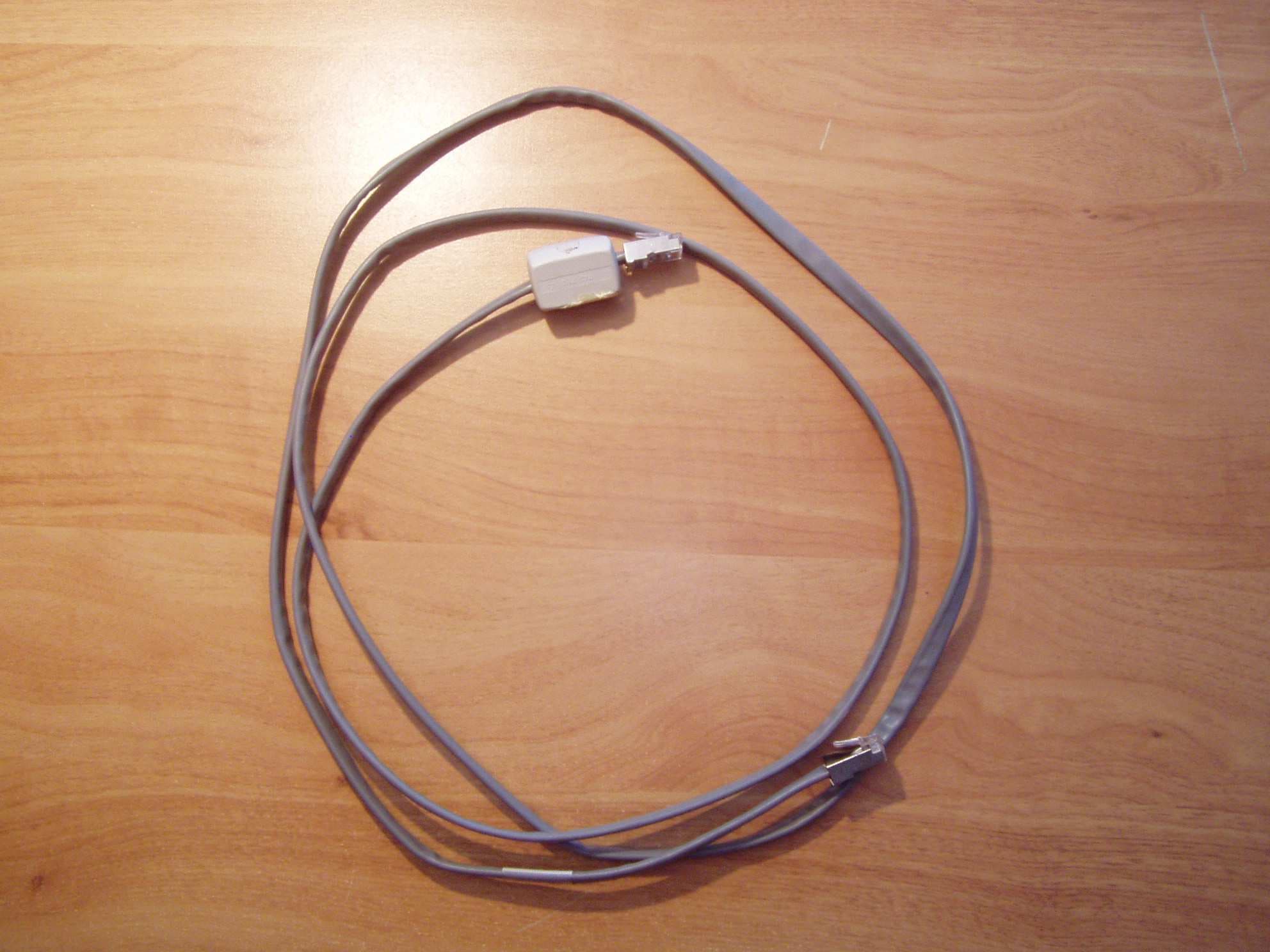
MESPROXU
Sep 12, 2006Tag Reader
Equipment Class
DXX - Part 15 Low Power Communication Device Transmitter