N5OD3DRCDRBMDRC-DR D3, DRC-BM D3
Scanreco AB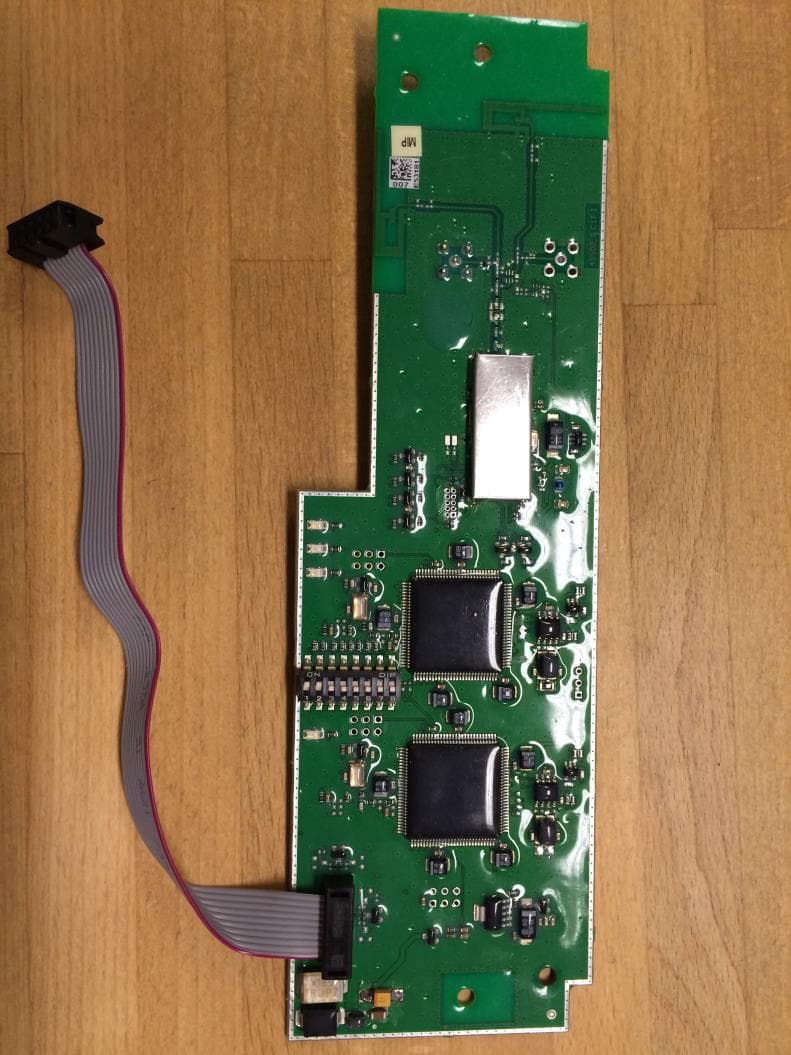
Click to zoom
Application Details
- Equipment Class
- DSS - Part 15 Spread Spectrum Transmitter
- Date of Grant
- Aug 25, 2015
- Application Purpose
- Original Equipment
- Date of Application
- Aug 25, 2015
- Equipment Note
- DRC-DR D3, DRC-BM D3
- Frequency Range
- 2405.00000000 - 2480.00000000
- Company
- Scanreco AB
- Country
- Sweden
Documents & Files
Document Text
Text extracted from the exhibit documents filed with the FCC. Open a document above to read the original.
Users Manual
Operating/assembly instructions DRC-DR D3 and DRC-BM D3 radio receivers 151014 enGB 211 267 44 719 IS 975 2 211 267 44.indd/151014 © Terex MHPS GmbH Further documents: DRC-10 D3 operating/assembly instructions 211 266 44 719 IS 975 DRC-J D3 operating/assembly instructions 211 271 44 719 IS 975 Manufacturer’s address: Original operating/assembly instructions Terex MHPS GmbH Forststrasse 16 40597 Düsseldorf, Germany www.demagcranes.com [email protected] 211 267 44.indd/151014 © Terex MHPS GmbH 3 Contents 1 General 4 1.1 Information on the DRC-DR radio receiver 4 1.2 General information 4 1.3 Information on the operating/assembly instructions 4 1.4 Symbols/signal words 5 1.5 Liability and warranty 6 1.6 Copyright 6 1.7 Spare parts 6 1.8 Definitions 7 1.9 After-sales service 8 1.10 Disposal of machine parts 8 2 Safety 9 2.1 General 9 2.2 Intended use 9 2.3 Responsibility of the owner 10 2.4 Operating personnel requirements 11 2.5 Personal protection equipment 11 2.6 Regular inspections 11 2.7 Safety instructions for installation and disassembly 11 2.8 Safety instructions when first putting the unit into service after completing installation 12 3 General description 13 3.1 Transmitter/receiver interface 13 3.2 Transmission method 13 4 Technical data 14 5 Putting the DRC-DR radio receiver into operation for the first time 15 5.1 Safety instructions 15 5.2 Installing the radio receiver card 16 5.3 Function following installation 18 5.4 Putting the receiver into operation for the first time 18 6 Using DRC radio controls 19 6.1 DRC-DR receiver operating functions in connection with a transmitter 19 6.1.1 F1 function key 19 6.1.2 F2 function key 19 6.1.3 F1/F2 function keys – additional functions 19 6.1.4 Horn key, 1st stage 19 6.1.5 Horn key, 2nd stage 19 7 International postal approval 20 P FCC and Industry Canada Information 22 4 211 267 44.indd/151014 © Terex MHPS GmbH 1 General You have purchased a Demag product. If special designs or additional options are ordered or the latest technical modifications are incorporated, the actual scope of supply may differ from the data and information as well as from the illustrations described here. If you have any questions, please contact the manufacturer. DRC-DR radio receivers may only be operated by personnel who are fully familiar with the operating/assembly instructions. DRC D3 (3rd generation) transmitters and receivers are successors to the D2 generation of DRC units. D3 units are to replace D2 generation radio systems wherever D3 units are allowed to be operated without the need for any registration or fees. In this context, see section 7 „International postal approval“. DRC D3 generation units are not technically compatible with units from the previous DRC D2 generation. This means that D3 generation transmitters and receivers cannot be combined with D2 units. These operating/assembly instructions are designed to provide the owner with appropriate instructions for safe and correct operation and for maintenance. These operating/assembly instructions are an integral part of the DRC-DR radio receiver. Every individual given the task of transporting, installing, commissioning, operating, maintaining and repairing DRC-DR radio receivers and their additional equipment must have read and understood the items listed in the following: • the operating/assembly instructions • the safety regulations • the safety instructions in the individual chapters and sections. The operating/assembly instructions must be available to operating personnel at all times in order to prevent operating errors and to ensure smooth and trouble-free operation of our products. They must be kept available in the immediate vicinity at all times. 1.1 Information on the DRC-DR radio receiver 1.2 General information 1.3 Information on the operating/assembly instructions 5 211 267 44.indd/151014 © Terex MHPS GmbH 1.4 Symbols/signal words NOTE Operating hazard for the DRC-DR radio receiver • This symbol indicates information on the appropriate use of DRC-DR re- ceivers. • Failure to follow these instructions may result in malfunctions, damage or pollution of the environment. DANGER. This symbol indicates an immediate hazard which can result in serious injury or death. WARNING. This symbol indicates a possibly hazardous situation which might result in seri- ous injury or death. CAUTION. This symbol indicates a possibly hazardous situation which might result in medium to light injury. i Important safety information and instructions are marked by corresponding sym- bols and signal words in these operating/assembly instructions. Safety instructions and information must be followed. Follow these instructions with care to avoid any accidents, injuries or damage. Any locally applicable accident prevention regulations and general safety regula- tions must also be followed. The following symbols and instructions warn against possible injuries or damage and are intended to assist you in your work. 6 211 267 44.indd/151014 © Terex MHPS GmbH Wearing parts are not subject to liability for defects. We reserve the right to incorporate technical modifications within the scope of improving the operating characteristics and further development of the DRC-DR radio receiver. These operating/assembly instructions must be treated confidentially. They are only intended to be used by people who work with or on the DRC-DR radio receiver. Any and all content, texts, drawings, images and any other information are protected within the sense of copyright law and are subject to further industrial rights. Any misuse is an offence. No part of this documentation, in whole or in part, may be reproduced, distributed, shown in public or used in any other way without specific prior consent. Infringe- ments are an offence resulting in obligatory compensatory damages. Further rights reserved. All industrial rights reserved. Only genuine Terex MH spare parts may be used. The use of unauthorised spare parts renders null and v…
Text truncated - open the document above for the full version.
Cover Letter(s)
Scanreco AB Årsta Skolgränd 22, Box 47144 SE-100 74, Stockholm, Sweden Tel +46 8 556 32 800 www.scanreco.com Attention: Application Examiner Re: Request for confidentiality Applicant: Scanreco AB FCC ID: N5OD3DRCDRBM Product Name: DRC-DR D3, DRC-BM D3 To whom it may concern, Permanent Confidentiality Request is hereby submitted by Scanreco AB to withhold permanently from public review certain portions of the application for equipment certification for the referenced FCC identifiers. This request for confidentiality is made pursuant to 47 CFR 0.457(d) and 0.459 of the FCC Rules. In particular, the following sections of the application are to be kept permanently confidential: • Schematics • Detailed Block diagrams • Detailed Operational/Functional Description • Parts list, Placement, BOM • Internal photos: This device will be installed only based on the NDA between the manufacturer and the installation company. The device will be professionally installed by our customers: Terex MHPS GmbH and Scanreco North American Inc. Internal photo illustrate the radio components shape and layout and give the possibility for competitors to recognize the radio platform and radio solution used. The layout of radio part is unique and is the proprietary intellectual property. Publishing of layout will disclose the design trade secrets and help to copy and theft the intellectual trade secrets with commercial and financial consequencies. Rationale for request for confidentiality: Scanreco AB has invested considerable time and materials in research and development to produce the referenced product. Disclosure of the permanently confidential portions of this application to competitors would not only give them significant competitive advantages in developing similar products, but would also disclose successful implementation of unpublished, leading edge technology developed by us. If you have questions or need further information, please contact the undersigned. Stockholm, Sweden, 02/02/2015 Sincerely, Andrei Sazonov, PhD Senior RF Specialist
Cover Letter(s)
EXTERNAL Page 1 of 1 Prepared by Product name/number Andrei Sazonov DRC-DR D3, DRC-BM D3 Document responsible (approved by) Checked Date: YYYY-MM-DD Release File Name Andrei Sazonov AS 2015-01-14 A SCANRECO - DRC-DR_BM D3 Single Modular Approval Cover Letter2.docx Scanreco AB Årsta Skolgränd 22, Box 47144 SE-100 74, Stockholm, Sweden Tel +46 8 556 32 800 www.scanreco.com Single Modular Approval Cover Letter according to requirement of 15.212 FCC ID: N5OD3DRCDRBM Following characteristics applies to the radio transceiver module designed and manufactured by Scanreco Industrielektronik AB: 1. The module has shielding. 2. All the inputs including data modulator input are buffered. 3. The module has its own power supply regulator. 4. The module is intended to work with the listed antenna by using its antenna contacts of SMB type. The product professionally installs by the Scanreco or its representatives under Scanreco control. 5. The module is fully tested in a stand-alone test fixture. The test fixture uses unmodified commercially available instrument to test the module. 6. The module is labelled with its own FCC ID number. Below is an example of the label. Warning text is in the user manual. 7. The module fulfils FCC Part 15.247. 8. The module complies to the RF exposure requirements. Andrei Sazonov, PhD Senior RF Specialist 01/14/2015 Revision history Release Date: YYYY-MM-DD Edited By Changes A 2015-01-14 Andrei Sazonov First creation of document
External Photos
External Photographs 277830-1 Scanreco DRC-DR D3 1 (1) Photograph 1. Front side of the EUT Photograph 2. Back side of the EUT
ID Label/Location Info
INTERNAL Page 1 of 1 Prepared by Product name/number Andrei Sazonov DRC-DR D3, DRC-BM D3 Document responsible (approved by) Checked Date: YYYY-MM-DD Release File Name Kristofer Hylén JEH 2014-12-19 B SCANRECO - DRC-DR_BM D3 Label Format and Location _2.docx Scanreco AB Årsta Skolgränd 22, Box 47144 SE-100 74, Stockholm, Sweden Tel +46 8 556 32 800 www.scanreco.com DRC-DR D3 and DRC-BM D3 Label Format and Location Front side of the device: Revision history Release Date: YYYY-MM-DD Edited By Changes A 2014-10-15 Andrei Sazonov First creation of document B 2014-12-19 Andrei Sazonov Label moved to the front side of the board
RF Exposure Info
INTERNAL Page 1 of 3 Prepared by Product name/number Andrei Sazonov DRC-DR D3, DRC-BM D3 Document responsible (approved by) Checked Date: YYYY-MM-DD Release File Name Kristofer Hylén JEH 2014-11-12 A SCANRECO - DRC-DR_BM D3 RF Exposure Exemption Analysis_2.docx Scanreco AB Årsta Skolgränd 22, Box 47144 SE-100 74, Stockholm, Sweden Tel +46 8 556 32 800 www.scanreco.com DRC-DR D3 and DRC-BM D3 RF Exposure Exemption Analysis Products: 2,4 GHz Radio modules DRC-10 D3 and DRC-10 2ST D3 Company: Scanreco AB, Box 47144/Årsta Skolgränd 22, S-10074, Stockholm, Sweden The radio module is designed for use in Scanreco industrial remote controls that are permanently installed to provide a separation distance of at least 20 cm from the user. The maximum duty cycle is 88,78%. The duty cycle is hardly coded in the firmware under production and cannot be changed by the user. From the pictures below the duty cycle is : Period: 6,4 s/83hits = 77,1ms Pulse length: 4,278ms Duty cycle: (4,278ms/77,1ms)*16channels = 88,78%. INTERNAL Page 2 of 3 Prepared by Product name/number Andrei Sazonov DRC-DR D3, DRC-BM D3 Document responsible (approved by) Checked Date: YYYY-MM-DD Release File Name Kristofer Hylén JEH 2014-11-12 A SCANRECO - DRC-DR_BM D3 RF Exposure Exemption Analysis_2.docx Scanreco AB Årsta Skolgränd 22, Box 47144 SE-100 74, Stockholm, Sweden Tel +46 8 556 32 800 www.scanreco.com INTERNAL Page 3 of 3 Prepared by Product name/number Andrei Sazonov DRC-DR D3, DRC-BM D3 Document responsible (approved by) Checked Date: YYYY-MM-DD Release File Name Kristofer Hylén JEH 2014-11-12 A SCANRECO - DRC-DR_BM D3 RF Exposure Exemption Analysis_2.docx Scanreco AB Årsta Skolgränd 22, Box 47144 SE-100 74, Stockholm, Sweden Tel +46 8 556 32 800 www.scanreco.com Revision history Release Date: YYYY-MM-DD Edited By Changes A 2014-11-12 Andrei Sazonov First creation of document
Test Report
Reference number: 277830-1 Page 2 of 30 Table of Contents PRODUCT DESCRIPTION .................................................................................................................................. 3 Equipment Under Test (EUT) .......................................................................................................................... 3 Ratings and declarations ................................................................................................................................. 3 Power Supply .................................................................................................................................................. 3 GENERAL REMARKS .......................................................................................................................................... 4 Disclaimer ........................................................................................................................................................ 4 SUMMARY OF TESTING ..................................................................................................................................... 5 EUT Test Conditions during Testing ............................................................................................................... 5 TEST RESULTS ................................................................................................................................................... 6 Conducted Emissions In The Frequency Range 150 kHz - 30 MHz. .............................................................. 6 Maximum Peak Conducted Output Power ...................................................................................................... 8 Transmitter Radiated Emissions 30 MHz to 26.5 GHz.................................................................................... 10 Conducted Spurious Emissions 30 MHz to 26.5 GHz and Band Edge ......................................................... 13 20 dB Bandwidth of the Hopping Channel ...................................................................................................... 21 Hopping Channel Carrier Frequencies Separation ......................................................................................... 23 Number of Hopping Channels ......................................................................................................................... 24 Average Time of Occupancy of Hopping Frequency ...................................................................................... 25 Duty cycle correction factor, Transmit time in 100 ms .................................................................................... 27 99% Occupied Power Bandwidth .................................................................................................................... 28 LIST OF TEST EQUIPMENT ............................................................................................................................... 30 Conducted Emissions ...................................................................................................................................... 30 Radiated Emissions ......................................................................................................................................... 30 Reference number: 277830-1 Page 3 of 30 Product Description PRODUCT DESCRIPTION Equipment Under Test (EUT) Wireless System-on-Module Type/ Model: DRC-DR D3 Serial Number: - DRC-DR D3 is a 2.4 GHz radio module that supports frequency hopping. The sample had an antenna connector and an external antenna. Conducted measurements were made with the sample having an external antenna. Measurements were made from the antenna connector (SMA). Classification of the device Fixed device Mobile Device (Human body distance > 20cm) Portable Device (Human body distance < 20cm) Modifications Incorporated in the EUT No modifications were applied to the EUT during testing. Ratings and declarations Operating Frequency Range (OFR): 2405 – 2480 MHz Channels: 16 Channel separation: 5 MHz Conducted power: 19.84 dBm Transmission technique: FHSS Modulation: GFSK Integrated antenna gain: - External antenna gain: 4.0 dBi Power Supply The following wall charger was used during the tests (supplied with 115 V/ 60 Hz). Charger: Manufacturer: Friwo Mobile Power Gmbh Model: FW7600/05 Serial number: - Input voltage: 100-240 VAC Rated current: 0.09A max Rated frequency: 50-60 Hz Output voltage: 5 V DC Output current: 0.65A max Reference number: 277830-1 Page 4 of 30 General remarks GENERAL REMARKS Disclaimer This test report is issued under SGS Fimko general terms of delivery (available on request and accessible at www.fi.sgs.com). Attention is drawn to the limitations of liability, indemnification and jurisdictional issues defined therein. Unless otherwise stated: (a) the results shown in this document refer only to the sample(s) tested and (b) such sample(s) are retained for three months. This document cannot be reproduced except in full, without prior approval of SGS Fimko. Any unauthorized alteration, forgery or falsification of the content or appearance of this report is unlawful and offenders may be prosecuted to the fullest extent of the law. Reference number: 277830-1 Page 5 of 30 Summary of Testing SUMMARY OF TESTING Test Specification Description of Test Result §15.207(a) / RSS-GEN 8.8 Conducted Emissions on Power Supply Lines PASS §15.247(b)(1) / RSS-210 8.4 Maximum Peak Conducted Output Power PASS 15.247(a)(1) / RSS-210 A8.1 Hopping Channel Carrier Frequency Separation PASS §15.247(a)(1)(iii) / RSS-210 A8.1 Number of Hopping Frequencies PASS §15.247(a)(1)(iii) / RSS-210 A8.1 Average Time of Occupancy of Hopping Frequency PASS §15.247(a)(1) / RSS-210 A8.1 20 dB Bandwidth PASS RSS-GEN 6.6 99 % Occupied Bandwidth PASS §15.247(d) / RSS-210 A8.5 100 kHz Bandwidth of Frequency Band Edges and Conducted Spurious Emissions PASS §15.209(a), §15.247(d)…
Text truncated - open the document above for the full version.
Test Setup Photos
Test Setup Photographs 277830-1 and 277830-1B Scanreco DRC-DR D3 1 (1) Photograph 1. Radiated emissions above 1000 MHz Photograph 2. Conducted emissions at mains ports 0.150 – 30 MHz
Contact Information
Applicant
Bjorn Askestig(Vice President)
Technical Contact
Non-Technical Contact
ScanrecoBjorn Askestig
Test Firm
SGS Fimko LtdJari Merikari
Technical Specifications
| # | Rule Parts | Frequency Range | Power Output |
|---|---|---|---|
| 1 | 15C | 2.40 GHz - 2.48 GHz | 96.00 mW |
Other Applications from Scanreco AB
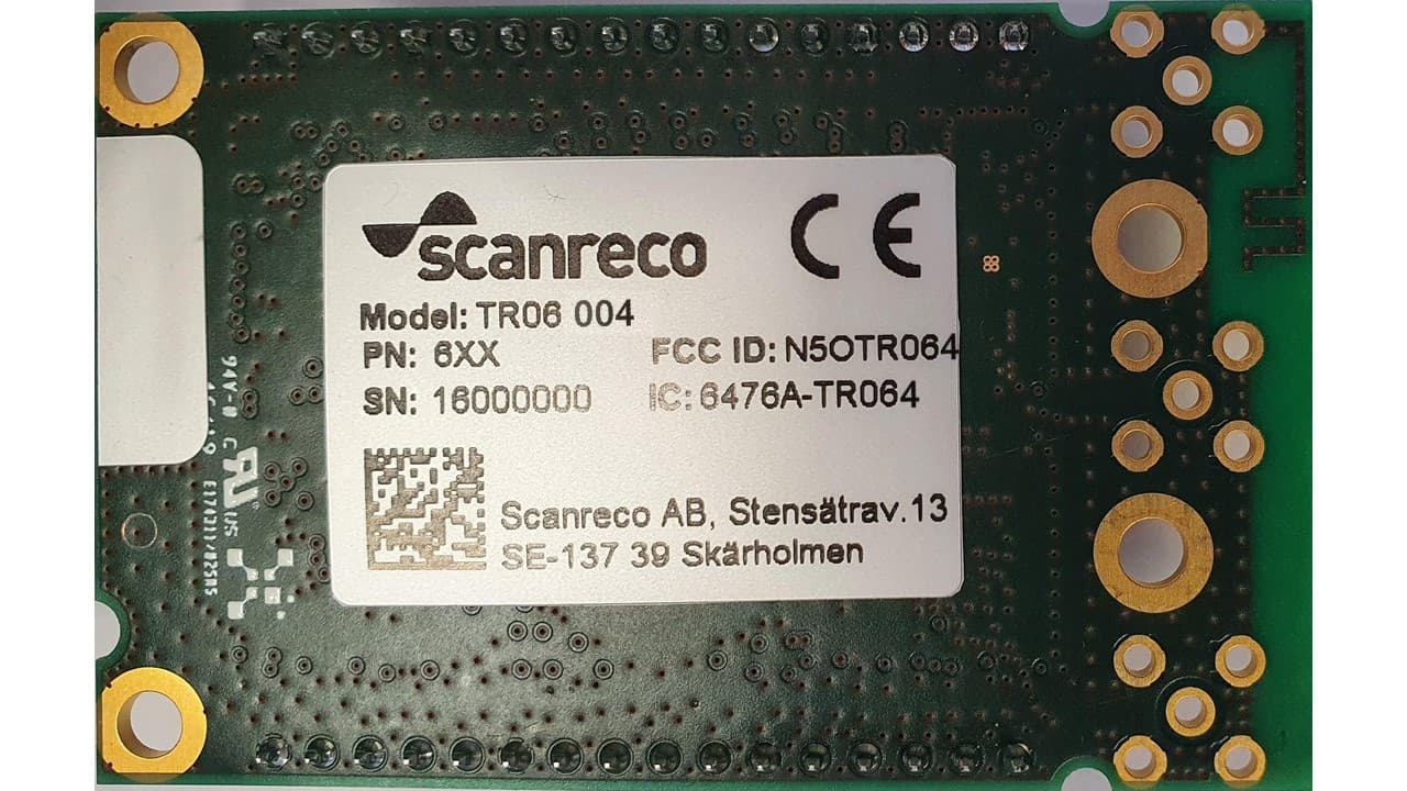
N5OTR064
Apr 25, 2021TR06 Transceiver Module
Equipment Class
DTS - Digital Transmission SystemN5OD3DRCJ
Apr 21, 20202.4 GHz Transceiver
Equipment Class
DSS - Part 15 Spread Spectrum TransmitterN5OD3DRCMP
Feb 03, 20202.4 GHz Transceiver
Equipment Class
DSS - Part 15 Spread Spectrum Transmitter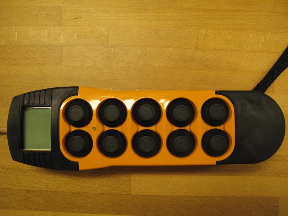
N5OD3DRC10
Aug 26, 20152.4 GHz Transceiver Model Number DRC-10 D3, DRC-10 2ST D3
Equipment Class
DSS - Part 15 Spread Spectrum Transmitter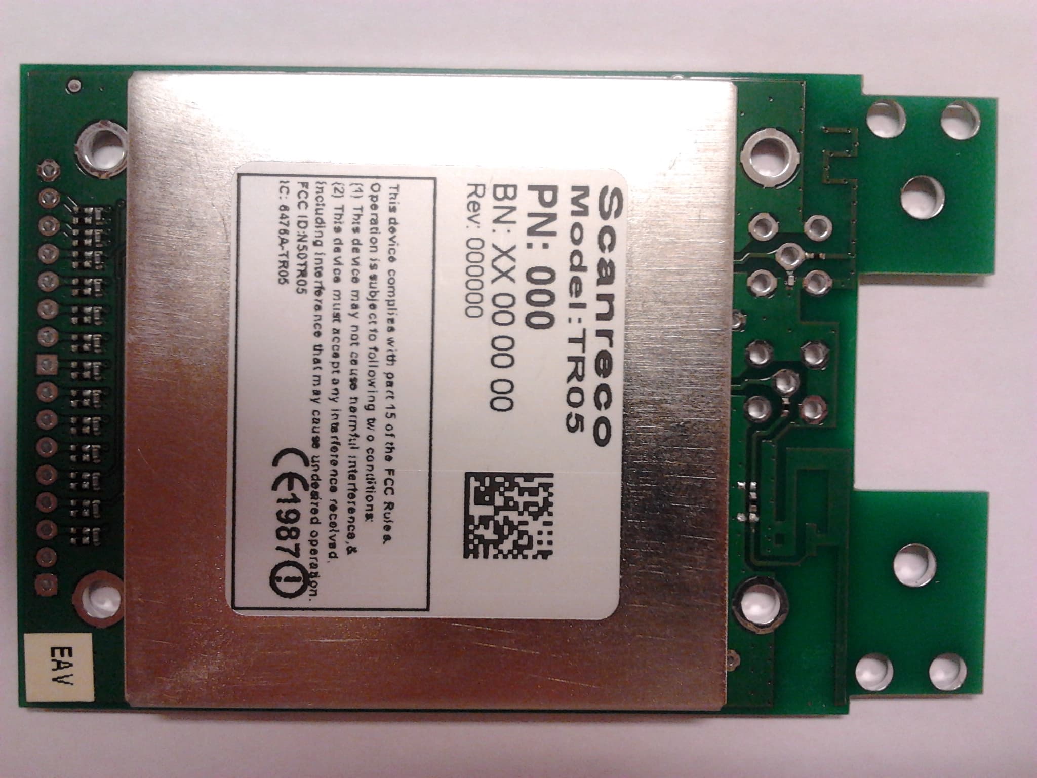
N5OTR05
Sep 02, 20142.4 GHz Transceiver
Equipment Class
DSS - Part 15 Spread Spectrum Transmitter