N5OD3DRCJ2.4 GHz Transceiver
Scanreco ABApplication Details
- Equipment Class
- DSS - Part 15 Spread Spectrum Transmitter
- Date of Grant
- Apr 21, 2020
- Application Purpose
- Original Equipment
- Date of Application
- Apr 21, 2020
- Equipment Note
- 2.4 GHz Transceiver
- Frequency Range
- 2405.00000000 - 2480.00000000
- Company
- Scanreco AB
- Country
- Sweden
Documents & Files
Document Text
Text extracted from the exhibit documents filed with the FCC. Open a document above to read the original.
Users Manual
Scanreco AB Stensätravägen 13, SE-127 39 Skärholmen Box 90304, SE-120 25 Stockholm, Sweden Tel +46 8 556 32 800 www.scanreco.com Portable control unit (transmitter) D3 DRC-J/JS D3 DRC-J: 2.4 GHz transmitter D3 DRC-JS: 2.4 GHz transmitter with key-operated safety switch D3 DRC-J Scanreco AB Stensätravägen 13, SE-127 39 Skärholmen Box 90304, SE-120 25 Stockholm, Sweden Tel +46 8 556 32 800 www.scanreco.com Example for a host product: Scanreco AB Stensätravägen 13, SE-127 39 Skärholmen Box 90304, SE-120 25 Stockholm, Sweden Tel +46 8 556 32 800 www.scanreco.com The difference between DRC-J and DRC-JS is that the model DRC-J does not have the safety key switch. This product is intended to be installed in a remote-control system as a transmitter and it is designed preferably for wireless control of crane installations, travelling hoist units, chain and rope hoists, transfer carriages and similar applications. The host products labels shall state: Contains FCC ID: N5OD3DRCJ Contains IC ID: 6476A-D3DRCJ RF Specification The D3 system family incorporates an automated frequency jumping technology, a reliable radio transmission highly resistant to interference. The radio transmission takes place within the ISM-band. Attribute Information Frequency 2.405 – 2.480 GHz Channels 16 Channels management FHSS Channel bandwidth 2.7 MHz RF Power +18 dBm typical Modulation GFSK Range 100 meter Antenna specification: N Antenna type Details Manufacture Part number Connector Gain 1 Inverted F-antenna Integral pcb antenna Scanreco 50127 Integral 0 dBi Scanreco AB Stensätravägen 13, SE-127 39 Skärholmen Box 90304, SE-120 25 Stockholm, Sweden Tel +46 8 556 32 800 www.scanreco.com Installation description: 1- Place the electronics board as shown in the Figure and make sure the flex cables are on the component side of the board 2- Connect the socket strips, actuators and the vibrator from the top according to Figure. 3- Tighten the board with screws 0.2Nm as shown in Figure. Note: The host products labels shall state: Contains FCC ID: NO5D3DRCJ Contains IC ID: 6476A-D3DRCJ Scanreco AB Stensätravägen 13, SE-127 39 Skärholmen Box 90304, SE-120 25 Stockholm, Sweden Tel +46 8 556 32 800 www.scanreco.com FCC information This equipment has been tested and found to comply with the limits for a Class a digital device, pursuant to part 15 of the FCC Rules. These limits are designed to provide reasonable protection against harmful interference when the equipment is operated in a commercial environment. This equipment generates, uses, and can radiate radio frequency energy and, if not installed and used in accordance with the instruction manual, may cause harmful interference to radio communications. Operation of this equipment in a residential area is likely to cause harmful interference in which case the user will be required to correct the interference at his own expense. This device complies with Part 15 of the FCC Rules. Operation is subject to the following two conditions: 1. This device may not cause harmful interference, and 2. This device must accept any interference received, including interference that may cause undesirable operation. FCC ID: N5OD3DRCJ Warning Changes or modifications not expressly approved by the party responsible for compliance could void the user’s authority to operate the equipment. Industry Canada information This device complies with Industry Canada licence-exempt RSS standard(s). Operation is subject to the following two conditions: (1) this device may not cause interference, and (2) this device must accept any interference, including interference that may cause undesired operation of the device. Le présent appareil est conforme aux CNR d’Industrie Canada applicables aux appareils radio exempts de licence. L’exploitation est autorisée aux deux conditions suivantes : (1) l’appareil ne doit pas produire de brouillage, et (2) l’utilisateur de l’appareil doit accepter tout brouillage radioélectrique subi, même si le brouillage est susceptible d’en compromettre le fonctionnement. CAN ICES-3 (A)/NMB-3(A) IC: 6476A-D3DRCJ
External Photos
Page 1 of 1 External Photos Exhibit Module – external photos same as internal.
ID Label/Location Info
D3 DRC-J label format and location SCANRECO Model: D3 DRC-J FCC ID: N5OD3DRCJ IC: 6476A-D3DRCJ The FCC warning text will be moved to the user operational manual due to lack of space.
RF Exposure Info
Scanreco AB Stensätravägen 13, SE-127 39 Skärholmen Box 90304, SE-120 25 Stockholm, Sweden Tel +46 8 556 32 800 www.scanreco.com D3 DRC-J RF Exposure Exemption Analysis Products: 2,4 GHz Transceivers D3 DRC-J The transceivers are designed for using as industrial hand-held / hand- operated remote control devices. The distance from the user to the antenna should be at least 20 cm. Therefore the body SAR is not required. Extremity SAR exclusion is based on 40mm separation distance. Minimum test separation distance “d”: see 4.3.1 of 447498 “The minimum test separation distance is determined by the smallest distance from the antenna and radiating structures or outer surface of the device, according to the host form factor, exposure conditions and platform requirements, to any part of the body or extremity of a user or bystander (see 5) of section 4.1).” The closest distance from the antenna to the user’s hand is 40,0mm The maximum duty cycle is 8.52 %. Scanreco AB Stensätravägen 13, SE-127 39 Skärholmen Box 90304, SE-120 25 Stockholm, Sweden Tel +46 8 556 32 800 www.scanreco.com FCC SAR Exclusion Analysis Section 4.3.1 of 447498 D01 General RF Exposure Guidance v05r02 Extremity SAR exclusion based on 40 mm separation distance and 8.52 % maximum duty cycle for this hand-hand operated device is documented below. P 20,20 dBm Tune-up tolerance 0,50 dB Duty Cycle 8,54 % P average 10,03 mW d 40 mm f 2480 MHz x 7,5 for 1-g SAR SAR exclusion 0,40 <7.5 Limit 7,5 Pmax 191 mW * calculated using 447498 D01 General RF Exposure Guidance v05r02 section 4.3.1 1) [(max. power of channel, including tune-up tolerance, mW)/(min. test separation distance, mm)] ·[√f(GHz) Scanreco AB Stensätravägen 13, SE-127 39 Skärholmen Box 90304, SE-120 25 Stockholm, Sweden Tel +46 8 556 32 800 www.scanreco.com Industry Canada SAR Exclusion Analysis RSS-102 Issue 4 2.5.1 Exemption from Routine Evaluation Limits – SAR Evaluation SAR evaluation is required if the separation distance between the user and the radiating element of the device is less than or equal to 20 cm, except when the device operates as follows: • above 2.2 GHz and up to 3 GHz inclusively, and with output power (i.e. the higher of the conducted or radiated (e.i.r.p.) source-based, time-averaged output power) that is less than or equal to 20 mW for general public use and 100 mW for controlled use; The maximum radiated (e.i.r.p) source-based time averaged output power is 10,01 mW. This is based on 8.52 % % duty cycle. RSS-102 exemption Notice_2013DRS0911 Extremity SAR Evaluation: SAR evaluation – exemption limits for routine evaluation based on frequency and separation distance at 2450 MHz, 40 mm, extremity = 173 x 2,5 = 432,5 mW. Revision history Release Date: YYYY-MM-DD Edited By Changes A 2019-11-06 Elnaz Farzaneh First creation of document
Test Report
Reference number: 295560-1-2 Page 2 of 46 Table of Contents GENERAL REMARKS ................................................................................................................................... 3 Disclaimer ................................................................................................................................................. 3 RELEASE HISTORY...................................................................................................................................... 4 Page 5: Trademark changed to Scanreco. ................................................................................................. 4 Page 11: Measuring distance added (3m). ................................................................................................ 4 Page 45: Calibration date of SMBV100A updated...................................................................................... 4 PRODUCT DESCRIPTION ............................................................................................................................ 5 Equipment Under Test .............................................................................................................................. 5 General Description .................................................................................................................................. 5 Ratings and declarations ........................................................................................................................... 5 Power Supply ............................................................................................................................................ 5 Mechanical Size of the EUT ...................................................................................................................... 5 SUMMARY OF TESTING .............................................................................................................................. 6 EUT Test Conditions during Testing .......................................................................................................... 6 TEST RESULTS ............................................................................................................................................ 8 Antenna requirement ................................................................................................................................. 8 Maximum Peak Conducted Output Power ................................................................................................. 9 Transmitter Radiated Spurious Emissions 9 kHz – 26.5 GHz ..................................................................... 12 Transmitter Band Edge Measurement and Conducted Spurious Emissions ............................................... 20 20 dB Bandwidth of the Hopping Channel ................................................................................................. 28 Hopping Channel Carrier Frequencies Separation ..................................................................................... 31 Number of Hopping Channels ................................................................................................................... 34 Average Time of Occupancy of Hopping Frequency .................................................................................. 36 6 dB Bandwidth of the Channel ................................................................................................................. 39 99% Occupied Bandwidth ......................................................................................................................... 42 Duty cycle correction factor, Transmit time in 100 ms ................................................................................ 45 TEST EQUIPMENT ....................................................................................................................................... 46 Reference number: 295560-1-2 Page 3 of 46 General Remarks GENERAL REMARKS Disclaimer This document is issued by the Company under its General Conditions of service accessible at http://www.sgs.com/terms_and_conditions.htm. attention is drawn to the limitation of liability, indemnification and jurisdiction issues defined therein. Any holder of this document is advised that information contained hereon reflects the Company's findings at the time of its intervention only and within the limits of Client's instructions, if any. The Company's sole responsibility is to its Client and this document does not exonerate parties to a transaction from exercising all their rights and obligations under the transaction documents. Any unauthorized alteration, forgery or falsification of the content or appearance of this document is unlawful and offenders may be prosecuted to the fullest extent of the law. Unless otherwise stated the results shown in this test report refer only to the sample(s) tested and such sample(s) are retained for 90 days only. This document cannot be reproduced except in full, without prior approval of the Company. Reference number: 295560-1-2 Page 4 of 46 Release History Test Report template version: 1.0 RELEASE HISTORY Version Changes Issued 1.0 Initial release 4 July 2019 1.1 spelling errors corrected Page 5: Trademark changed to Scanreco. Page 11: Measuring distance added (3m). Page 45: Calibration date of SMBV100A updated 12 August 2019 Reference number: 295560-1-2 Page 5 of 46 Product Description PRODUCT DESCRIPTION Equipment Under Test Trade mark: Scanreco Model: D3 DRC-J Type: PN: 50504, Rev: A Serial no: 004715 (conducted measurements), 004716 (radiated measurements) FCC ID: N5OD3DRCJ IC: 6476A-D3DRCJ General Description EUT is 2.4GHz radio module that supports frequency hopping (FHSS). The EUT has been tested as a radio module. A part of a typical host (plastic) was needed when testing in order to control the radio module and obtain full functionality. Classification Fixed device Mobil…
Text truncated - open the document above for the full version.
Test Setup Photos
Test Setup Photographs 1 (4) 295560-1-2 SGS Fimko Ltd Särkiniementie 3, PO Box 30 FI-00211 Helsinki, Finland t. +358 9 696 361 f. +358 9 692 5474 www.fi.sgs.com Business ID 0978538-5 Member of the SGS Group (SGS SA) Photograph 1. EUT, radiated sample Photograph 2.Serial number, radiated EUT Test Setup Photographs 2 (4) 295560-1-2 SGS Fimko Ltd Särkiniementie 3, PO Box 30 FI-00211 Helsinki, Finland t. +358 9 696 361 f. +358 9 692 5474 www.fi.sgs.com Business ID 0978538-5 Member of the SGS Group (SGS SA) Photograph 3 EUT with antenna port for conducted tests. Photograph 4. Serial number, conducted EUT Test Setup Photographs 3 (4) 295560-1-2 SGS Fimko Ltd Särkiniementie 3, PO Box 30 FI-00211 Helsinki, Finland t. +358 9 696 361 f. +358 9 692 5474 www.fi.sgs.com Business ID 0978538-5 Member of the SGS Group (SGS SA) Photograph 5. Radiated Spurious Emissions 9 kHz – 30 MHz Photograph 6. Radiated Spurious Emissions 30 MHz – 1000 MHz Test Setup Photographs 4 (4) 295560-1-2 SGS Fimko Ltd Särkiniementie 3, PO Box 30 FI-00211 Helsinki, Finland t. +358 9 696 361 f. +358 9 692 5474 www.fi.sgs.com Business ID 0978538-5 Member of the SGS Group (SGS SA) Photograph 7. Radiated Spurious Emissions 1 GHz – 18 GHz Photograph 8. Radiated Spurious Emissions 18 GHz – 26.5 GHz
Contact Information
Applicant
Bjorn Askestig(Vice President)
Technical Contact
Non-Technical Contact
Scanerco ABBjorn Askestig
[email protected]46 8 556 32 801
Test Firm
SGS Fimko OyJanne Nyman
Technical Specifications
| # | Rule Parts | Frequency Range | Power Output |
|---|---|---|---|
| 1 | 15C | 2.40 GHz - 2.48 GHz | 105.00 mW |
Other Applications from Scanreco AB
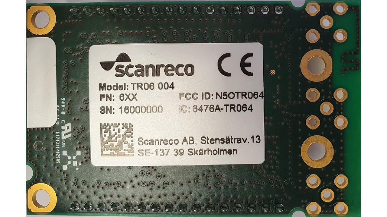
N5OTR064
Apr 25, 2021TR06 Transceiver Module
Equipment Class
DTS - Digital Transmission SystemN5OD3DRCMP
Feb 03, 20202.4 GHz Transceiver
Equipment Class
DSS - Part 15 Spread Spectrum Transmitter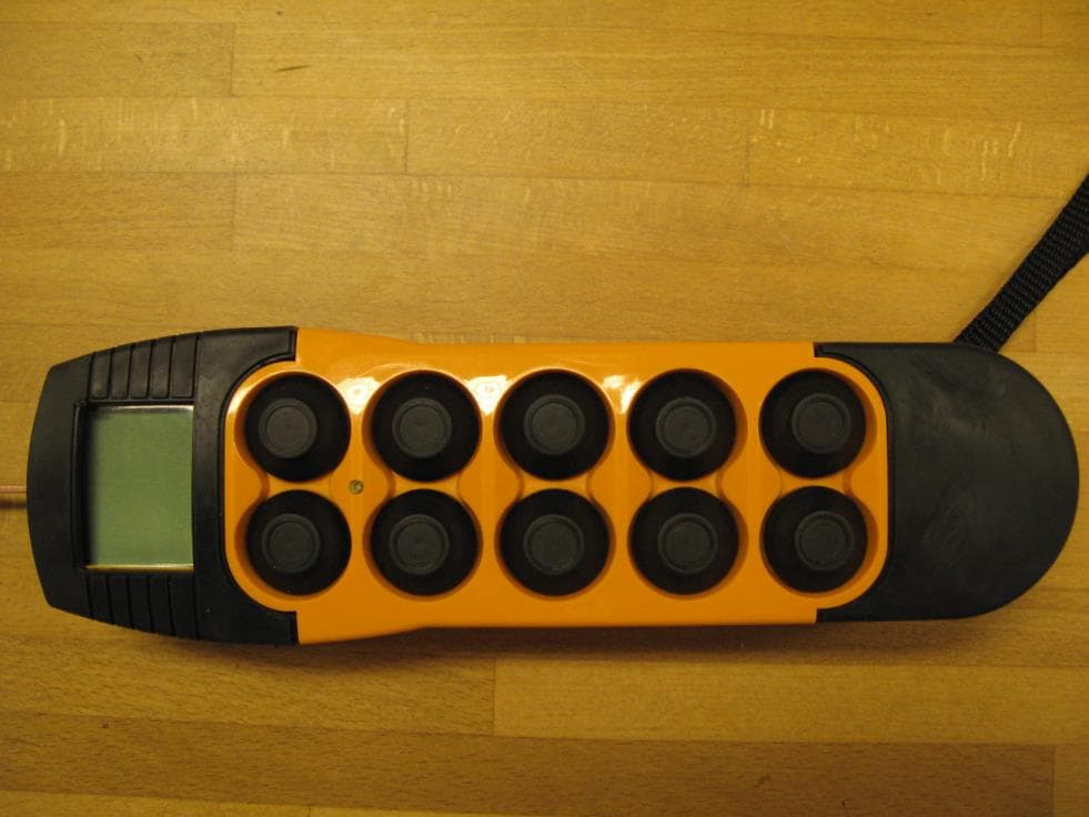
N5OD3DRC10
Aug 26, 20152.4 GHz Transceiver Model Number DRC-10 D3, DRC-10 2ST D3
Equipment Class
DSS - Part 15 Spread Spectrum Transmitter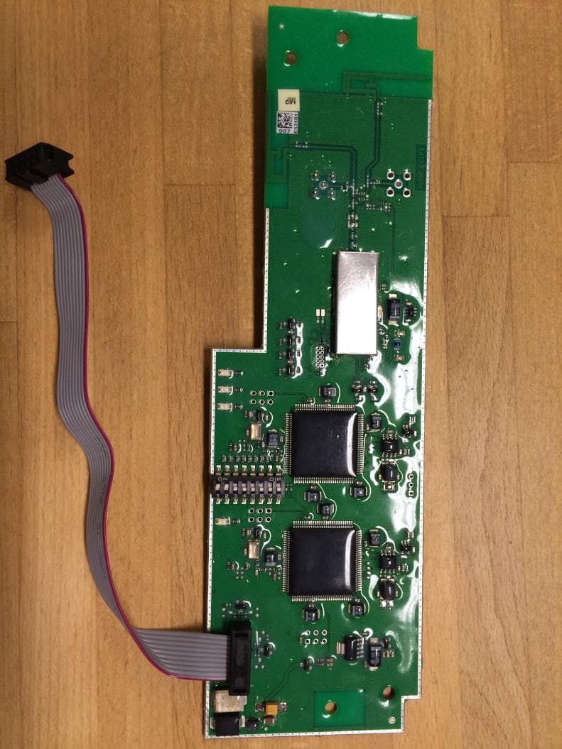
N5OD3DRCDRBM
Aug 25, 2015DRC-DR D3, DRC-BM D3
Equipment Class
DSS - Part 15 Spread Spectrum Transmitter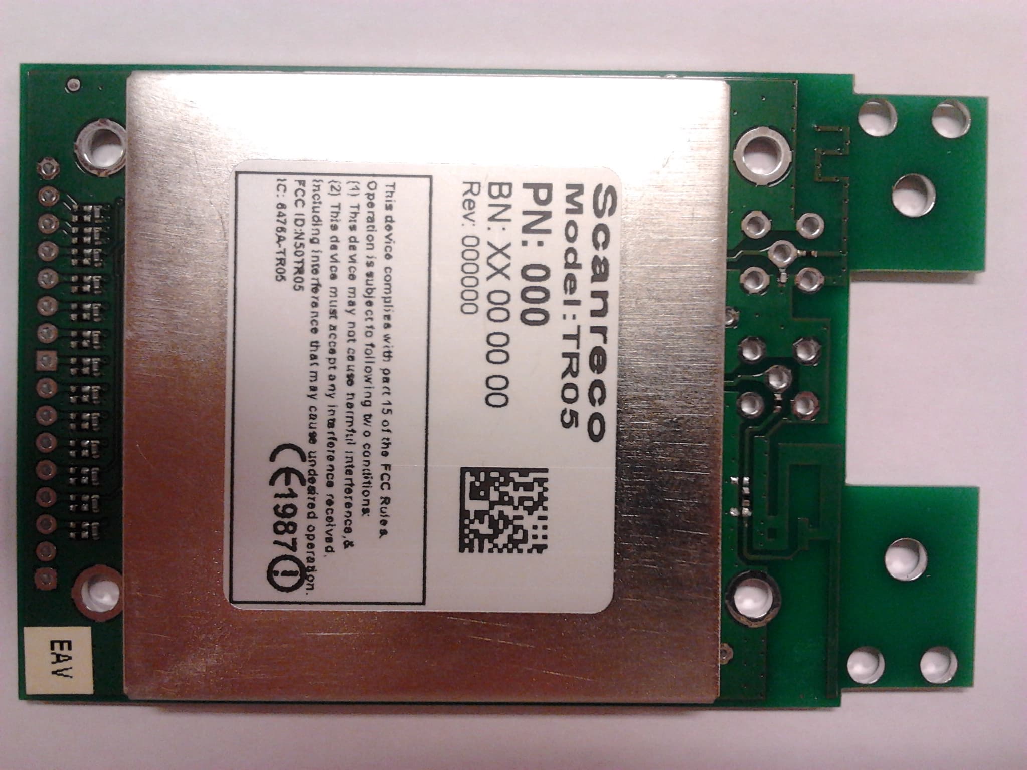
N5OTR05
Sep 02, 20142.4 GHz Transceiver
Equipment Class
DSS - Part 15 Spread Spectrum Transmitter