N5OTR064TR06 Transceiver Module
Scanreco AB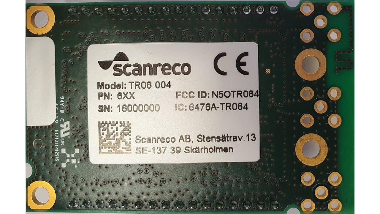
Click to zoom
Application Details
- Equipment Class
- DTS - Digital Transmission System
- Date of Grant
- Apr 25, 2021
- Application Purpose
- Original Equipment
- Date of Application
- Mar 18, 2021
- Equipment Note
- TR06 Transceiver Module
- Frequency Range
- 2405.00000000 - 2480.00000000
- Company
- Scanreco AB
- Country
- Sweden
Documents & Files
Document Text
Text extracted from the exhibit documents filed with the FCC. Open a document above to read the original.
Users Manual
USER MANUAL Page 1 of 9 Prepared by Product name/number Andrei Sazonov TR06 radio module Document responsible (approved by) Checked Date: YYYY-MM-DD Release File Name Andrei Sazonov 2021-03-15 F TR06 User Manual TR06 Radio Module User Manual D e v e l o p e d f o r d e m a n d i n g e n v i r o n m e n t s Scanreco ́s TR06 is built and designed for the toughest and most demanding of environments. Scanreco can hereby offer the market of crane and machine operators an extremely easy to use radio remote control retaining speed, precision, and control with the maximum of safety. Behind the development of the radio transeivers lies the idea of providing a product with a high degree of reliability, user-friendliness, and easy upgrade for cable systems or other data radio applications. The product family includes different transeivers and receivers offering a variety of choice depending on the area of use. These products are based on a modular architecture, which makes them extremely flexible to customize and adapt according to the customer’s needs. The products – which are in high demand – are mainly mounted on cranes and mobile machines. Our customers are some of the world’s largest and most challenging crane and machinery manufacturers. Thousands of cranes and machines containing Scanreco’s radio products are in use worldwide. Our products are deployed everywhere, from truck cranes laying heating pipes in Stockholm to lifting oil pipelines in Russia and setting in place concrete sections in Singapore. Scanreco – W h a t d o y o u w a n t t o r e m o t e ? Our customers development is our own development. This enables us to offer: • Customer-specific solutions • Industrial know-how • Expertise and experience • Innovative capacity • Nimble organisation • Quality • Delivery precision • S e r v i c e www.scanreco.se USER MANUAL Page 2 of 9 Prepared by Product name/number Andrei Sazonov TR06 radio module Document responsible (approved by) Checked Date: YYYY-MM-DD Release File Name Andrei Sazonov 2021-03-15 F TR06 User Manual TR06 Radio Module Parameters for 2,4GHz band Attribute Information Frequency 2405 – 2480 MHz Channels 16 (5MHz step) Channel management FHSS, DSSS Channel order Pseudorandom Channel bandwidth 2,7MHz Modulation QPSK Power 125mW max Type Transceiver TR06 Radio Module Parameters for 915Hz band Attribute Information Frequency 903,5 – 926,53 MHz Channels 50 Channel management FHSS Channel order Pseudorandom Channel bandwidth 100 kHz Data rate 50 kbps Modulation FSK Power 1W max Type Transceiver USER MANUAL Page 3 of 9 Prepared by Product name/number Andrei Sazonov TR06 radio module Document responsible (approved by) Checked Date: YYYY-MM-DD Release File Name Andrei Sazonov 2021-03-15 F TR06 User Manual TR06 Radio Module RF and I/O Interfaces RF1 and RF2 are the radio connectors for the 900MHz frequency band. RF2 and RF3 are the radio connectors for the 2,4GHz frequency band. K1 and K2 are digital interface and power supply connectors. TR06 Radio Module Power Sourcing Voltage Nominal, V Max, V VCC Radio 3 3,4 VCC Amplifier 3,4 4,0 RF1 RF2 RF3 USER MANUAL Page 4 of 9 Prepared by Product name/number Andrei Sazonov TR06 radio module Document responsible (approved by) Checked Date: YYYY-MM-DD Release File Name Andrei Sazonov 2021-03-15 F TR06 User Manual TR06 Radio Module Integration This product is intended to be installed in a remote-control system as a transmitter and it is designed preferably for wireless control of crane installations, travelling hoist units, chain and rope hoists, transfer carriages and similar applications. The host products labels shall state depending on the model used: Contains FCC ID: N5OTR061, Contains IC ID: 6476A-TR061, Contains FCC ID: N5OTR062, Contains IC ID: 6476A-TR062, Contains FCC ID: N5OTR064, Contains IC ID: 6476A-TR064. Host exemple: 1 – Remote control; 2 – Control box USER MANUAL Page 5 of 9 Prepared by Product name/number Andrei Sazonov TR06 radio module Document responsible (approved by) Checked Date: YYYY-MM-DD Release File Name Andrei Sazonov 2021-03-15 F TR06 User Manual Remote Controls “MIco” and “Mini” Control box USER MANUAL Page 6 of 9 Prepared by Product name/number Andrei Sazonov TR06 radio module Document responsible (approved by) Checked Date: YYYY-MM-DD Release File Name Andrei Sazonov 2021-03-15 F TR06 User Manual Installation description: 1. Mount the TR06 radio module on a main electronics boards with help of 4 screws. Solder the radio modules pinheaders or use connectors for establish the electrical contacts with a main board. 2. Mount the main board with the TR06 radio module inside a host. Note: The host products labels shall state: Contains FCC ID: N5OTR061, Contains IC ID: 6476A-TR061 Contains FCC ID: N5OTR062, Contains IC ID: 6476A-TR062 Contains FCC ID: N5OTR064, Contains IC ID: 6476A-TR064 Antennas For available antennas – please, see the document “Theory of operation of TR06 radio module. In hand-held / hand operated hosts for 915MHz band just antennas with max gain 0dBi should be used (for example art. n. 103003 and 102986). Test modes and additional testing The special test software for measurement of radio parameters and spurious emission is provided. TR06 radio module compiles with Part 15.247 of FCC Rules. But final host product still requires the Part 15 Subpart B compliance testing with the radio modul installed. USER MANUAL Page 7 of 9 Prepared by Product name/number Andrei Sazonov TR06 radio module Document responsible (approved by) Checked Date: YYYY-MM-DD Release File Name Andrei Sazonov 2021-03-15 F TR06 User Manual FCC Information This equipment has been tested and found to comply with the limits for a Class B digital device, pursuant to part 15 of the FCC Rules. These limits are designed to provide reasonable protection against harmful interference when the equipment is operated in a commercial environment. This equipment generates,uses, and can radiate radio frequency energy and, if not installed and use…
Text truncated - open the document above for the full version.
Cover Letter(s)
Scanreco AB Stensätravägen 13, SE-127 39 Skärholmen Box 90304, SE-120 25 Stockholm, Sweden Tel +46 8 556 32 800 www.scanreco.com Model Differences Letter TR06 FCC ID: N5OTR061, N5OTR062, N5OTR064 IC: 6476A-TR061, 6476A-TR062, 6476A-TR064 The same printed circuit board is used for the different radio module models. Different frequencies (f. ex. 915MHz and 2,4GHz) can not be transmitted simultaneously, just one in time. TR06 radio module models are described in the table: Model name Description FCC/IC ID Components belonging just to the 2,4GHz radio part are assembled on the board. FCC ID: N5OTR061 IC: 6476A-TR061 Components belonging to the 2,4GHz and 915MHz parts are assembled on the board. FCC ID: N5OTR062 IC: 6476A-TR062 Components belonging to the 2,4GHz, 915MHz and additional sub-GHz radio parts are assembled on the board. FCC ID: N5OTR064 IC: 6476A-TR064 For more detailed information, please, see the document Theory of Operation of TR06 Radio Module TR06-001 TR06-002 TR06-004
External Photos
Scanreco AB Stensätravägen 13, SE-127 39 Skärholmen Box 90304, SE-120 25 Stockholm, Sweden Tel +46 8 556 32 800 www.scanreco.com TR06 External Photos FCC ID: N5OTR064 IC: 6476A-TR064
ID Label/Location Info
Scanreco AB Stensätravägen 13, SE-127 39 Skärholmen Box 90304, SE-120 25 Stockholm, Sweden Tel +46 8 556 32 800 www.scanreco.com TR06 Label Design, Material and Position FCC ID: N5OTR061, N5OTR062, N5OTR064 IC: 6476A-TR061, 6476A-TR062, 6476A-TR064 3M Polyester Label The FCC warning text is moved to User manual due to lack of space. - - - -
RF Exposure Info
FCC ID: N5OTR064 FCC 1.1310 General Population/Uncontrolled Exposure Frequency (F)Power (P) Duty Cycle Duty Cycle (D) Antenna Gain (G)EIRP 1 EIRP Distance (R) Power Density 2 (PD)Limit 3 Margin MHzdBm%dBdBidBmmWcm mW/m 2 mW/cm 2 dB FHSS914.7829.6521.00-6.78628.9771.29200.153440.6106.0 FHSS248020.684.30-13.67613.020.02200.0041.024.0 DSSS248016.754.30-13.6769.18.10200.00161.027.93 IC: 6476A-TR064 CANADA RSS-102, Issue 5 General Population/Uncontrolled Exposure Frequency (F)Power (P) Duty Cycle Duty Cycle (D) Antenna Gain (G)EIRP 1 EIRP Distance (R) Power Density 2 (PD)Limit 4 Magin Exemption Limit 5 MHzdBm%dBdBidBmWm W/m 2 W/m 2 dBW FHSS914.7829.6521.00-6.78628.90.771290.21.53442.772.561.38 FHSS248020.684.30-13.67613.00.020020.20.045.46921.42.74 DSSS248016.754.30-13.6769.10.008100.20.0165.4725.32.74 1 EIRP = P + D + G 2 Power Density = EIRP/(4xπxR 2 ); Health Canada Technical Guide - Safety Code 6_2015, Eq 5-6 at 5.2; OET Bulletin 65, Edition 97-01, August 1997, Eq (4) 3 FCC 1.1310 Table 1; Limit = F/1500 (300 ≤ F ≤ 1,500); Limit = 1 (1,500 MHz ≤ F ≤ 100,000 MHz) 4 RSS-102 Issue 5 Table 4; Limit = 0.02619 x F 0.6834 (300 MHz ≤ F ≤ 6,000 MHz) 5 RSS-102 Issue 5 at 2.5.2; Exemption Limit = 1.31 x 10 -2 x F 0.6834 (300 MHz ≤ F < 6 GHz)
RF Exposure Info
FCC ID: N5OTR064 SAR Exclusion Justification Test exclusion thresholds for 100 MHz to 6 GHz at test separation distances ≤ 50 mm Guidance document reference: 447498 D01 General RF Exposure Guidance v05r02, page 11, paragraph 4.3.1(1). The 1-g and 10-g SAR test exclusion thresholds for 100 MHz to 6 GHz at test separation distances ≤ 50 mm are determined by: [(max. power of channel, including tune-up tolerance, mW)/(min. test separation distance, mm)] * [√f(GHz)] ≤ 3.0 for 1-g SAR and ≤ 7.5 for 10-g extremity SAR, where • f(GHz) is the RF channel transmit frequency in GHz • Power and distance are rounded to the nearest mW and mm before calculation • The result is rounded to one decimal place for comparison • 3.0 and 7.5 are referred to as the numeric thresholds in the step 2 below The test exclusions are applicable only when the minimum test separation distance is ≤ 50 mm and for transmission frequencies between 100 MHz and 6 GHz. When the minimum test separation distance is < 5 mm, a distance of 5 mm according to 5) in section 4.1 is applied to determine SAR test exclusion. SAR test exclusion analysis: Assumptions: Since the exact separation distance may vary from sensor to sensor, the minimum separation distance of 5 mm is assumed per the guidance document. Max,Power of Channel: 16.75 dBm Tune up tolerance: 0.5 dB Duty Cycle: 4.3 % Average power 2.28 Min. separation distance: 5 mm Max. frequency: 2.48 GHz [(Pwr/Dist)* √ Freq.] = 0.72 Max. power is source-based time-averaged maximum conducted output power, adjusted for tune-up tolerance. The result of the above SAR threshold calculation demonstrates that the result is less than the 1-g numeric threshold of 3 and the 10-g numeric threshold of 7.5. Conclusion: The above analysis shows that the evaluated device qualifies for exemption from SAR testing. Signed: , Senior Enginner 3/2/2021
Test Report
Report No. 400635-023-R02 Template version: C Nemko Norway Nemko AS, Instituttveien 6, P.O. Box 96 Kjeller, 2027 Kjeller, Norway TEL +47 22 96 03 30 FAX +47 22 96 05 50 EMAIL [email protected] ENTERPRISE NUMBER NO974404532 nemko.com/no Test Report Product Transceiver Module Name and address of the applicant Scanreco AB Stensätravägen 13, SE-127 39 Skärholmen Box 90304, SE-120 25 Stockholm SWEDEN Name and address of the manufacturer Scanreco AB Stensätravägen 13, SE-127 39 Skärholmen Box 90304, SE-120 25 Stockholm SWEDEN Model TR06-004 Rating 3.4Vdc and 4.0Vdc, Battery Trademark Scanreco Serial number See page 3 Additional information 2.4GHz, DTS, Radio module Tested according to FCC Part 15.247 Frequency Hopping Transmitters / Digital Transmission Systems Industry Canada RSS-247, Issue 2 Digital Transmission Systems (DTSs), Frequency Hopping Systems (FHSs) and Licence-Exempt Local Area Network (LE-LAN) Devices Order number 400635 Tested in period 2020.06.24 – 2020.08.12 Issue date 2021.01.18 Name and address of the testing laboratory Instituttveien 6 Kjeller, Norway CAB Number: FCC: NO0001 ISED: NO0470 TEL: +47 22 96 03 30 FAX: +47 22 96 05 50 An accredited technical test executed under the Norwegian accreditation scheme Prepared by [G.Suhanthakumar] Approved by [Frode Sveinsen] This report shall not be reproduced except in full without the written approval of Nemko. Opinions and interpretations expressed within this report are not part of the current accreditation. This report was originally distributed electronically with digital signatures. For more information contact Nemko. TEST REPORT FCC Part 15.247 Report no.: 400635-023-R02 FCC ID: N5OTR064 Nemko Norway, Instituttveien 6, Kjeller, Norway Page 2 (94) CONTENTS 1 INFORMATION ......................................................................................................................... 3 1.1 Test Item .................................................................................................................................... 3 1.2 Normal test condition ................................................................................................................. 4 1.3 Test Engineer(s) ........................................................................................................................ 4 1.4 Model Variants ........................................................................................................................... 4 1.5 Antenna Requirement ................................................................................................................ 4 1.6 Worst-Case Configuration and Mode ......................................................................................... 5 1.7 Comments ................................................................................................................................. 5 2 TEST REPORT SUMMARY ...................................................................................................... 6 2.1 General ...................................................................................................................................... 6 2.2 Test Summary ........................................................................................................................... 7 3 TEST RESULTS ........................................................................................................................ 8 3.1 Occupied Bandwidth .................................................................................................................. 8 3.2 DTS Bandwidth ........................................................................................................................ 11 3.3 Peak Power Output .................................................................................................................. 15 3.4 Conducted Emissions at Antenna Connector .......................................................................... 25 3.5 Restricted Bands of operation.................................................................................................. 29 3.6 Band Edge Emissions (Radiated) ............................................................................................ 30 3.7 Radiated emissions 30 – 1000 MHz. ....................................................................................... 36 3.8 Radiated Emissions, 1-25 GHz ................................................................................................ 39 3.9 Power Spectral Density (PSD) ................................................................................................. 88 4 Measurement Uncertainty ..................................................................................................... 92 5 LIST OF TEST EQUIPMENT................................................................................................... 93 6 BLOCK DIAGRAM .................................................................................................................. 94 6.1 Power Line Conducted Emission ............................................................................................. 94 6.2 Test Site Radiated Emission .................................................................................................... 94 TEST REPORT FCC Part 15.247 Report no.: 400635-023-R02 FCC ID: N5OTR064 Nemko Norway, Instituttveien 6, Kjeller, Norway Page 3 (94) 1 INFORMATION 1.1 Test Item Name Transceiver Module FCC ID TR06-004: N5OTR064 ISED ID TR06-004: 6476A-TR064 Model/version TR06-004 Serial number Marked as “DTS” Hardware identity and/or version 102112 Software identity and/or version G6COMM_TEST Frequency Range 2405 – 2480 MHz Channel Separation 5 MHz Number of Channels 16 Operating Modes TX and RX Measured BW (99%) 2.61 MHz Emission clasification F2D Transmitter spurious, dBμV/m@3m PK: 68.35; AV: 48.35 ((2.4835GHz) Type of Modulation O-QPSK, DTS User Frequency Adjustment None Conducted Output Power, Max 47.32 mW…
Text truncated - open the document above for the full version.
Test Setup Photos
TEST SET-UP PHOTOS Project no.: 400635 FCC ID: N5OTR061 FCC ID: N5OTR062 FCC ID: N5OTR064 Page 1 (2) PHOTOS OF TEST SET-UP Radiated emissions below 30MHz Radiated emission 30MHz - 1 GHz with monopole antenna Radiated emission 30MHz - 1 GHz with dipole antenna Radiated emissions above 1 GHz with monopole antenna TEST SET-UP PHOTOS Project no.: 400635 FCC ID: N5OTR061 FCC ID: N5OTR062 FCC ID: N5OTR064 Page 2 (2) Radiated emissions above 1 GHz with dipole antenna Radiated emissions above 1 GHz with monopole antenna Radiated emissions above 1 GHz with dipole antenna
Contact Information
Applicant
Bjorn Askestig(Vice President)
Test Firm
Nemko Scandinavia ASFrode Sveinsen
[email protected]+4796905548
Technical Specifications
| # | Rule Parts | Frequency Range | Power Output |
|---|---|---|---|
| 1 | 15C | 2.40 GHz - 2.48 GHz | 47.00 mW |
Other Applications from Scanreco AB
N5OD3DRCJ
Apr 21, 20202.4 GHz Transceiver
Equipment Class
DSS - Part 15 Spread Spectrum TransmitterN5OD3DRCMP
Feb 03, 20202.4 GHz Transceiver
Equipment Class
DSS - Part 15 Spread Spectrum Transmitter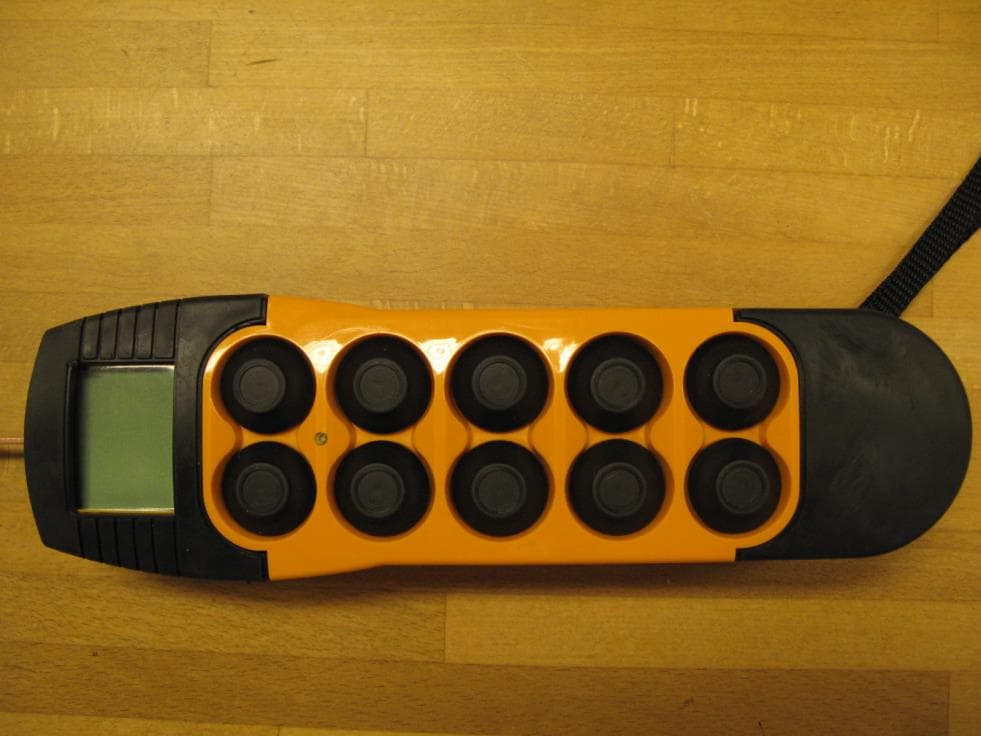
N5OD3DRC10
Aug 26, 20152.4 GHz Transceiver Model Number DRC-10 D3, DRC-10 2ST D3
Equipment Class
DSS - Part 15 Spread Spectrum Transmitter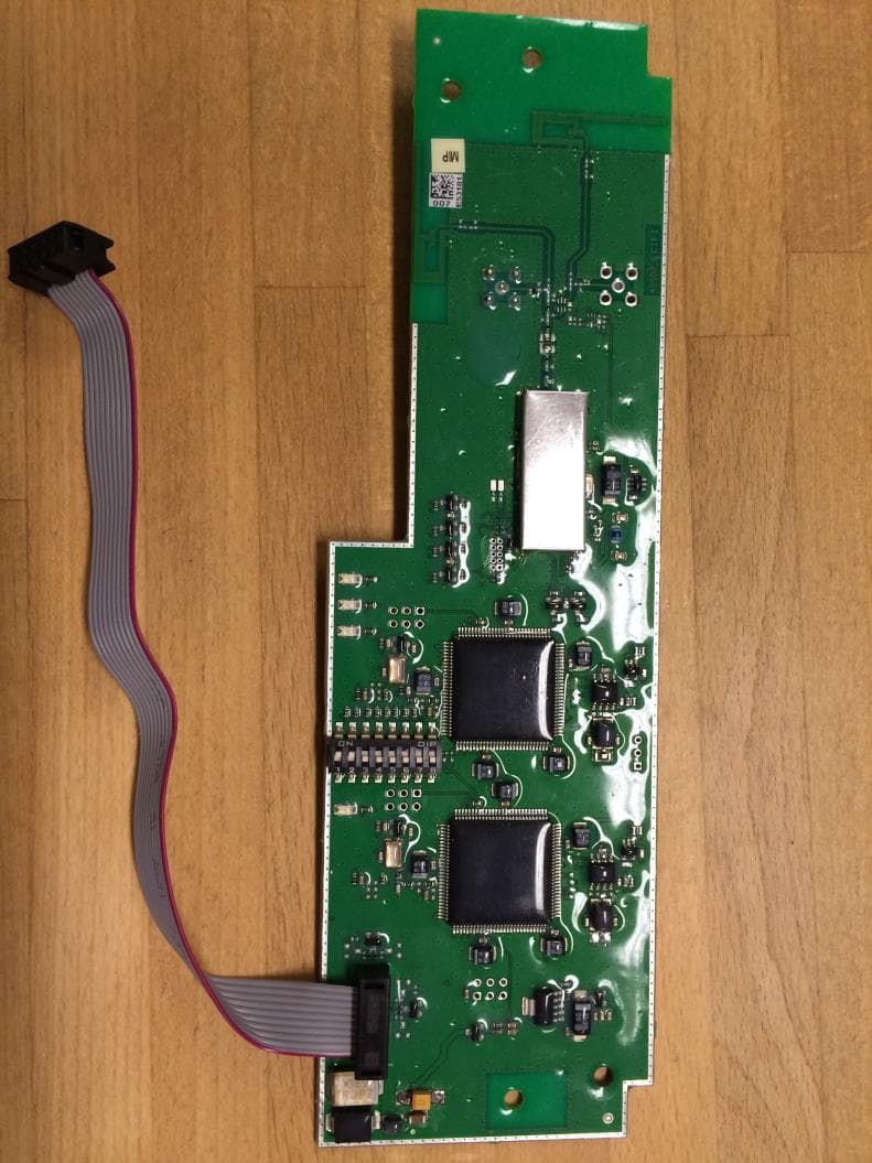
N5OD3DRCDRBM
Aug 25, 2015DRC-DR D3, DRC-BM D3
Equipment Class
DSS - Part 15 Spread Spectrum Transmitter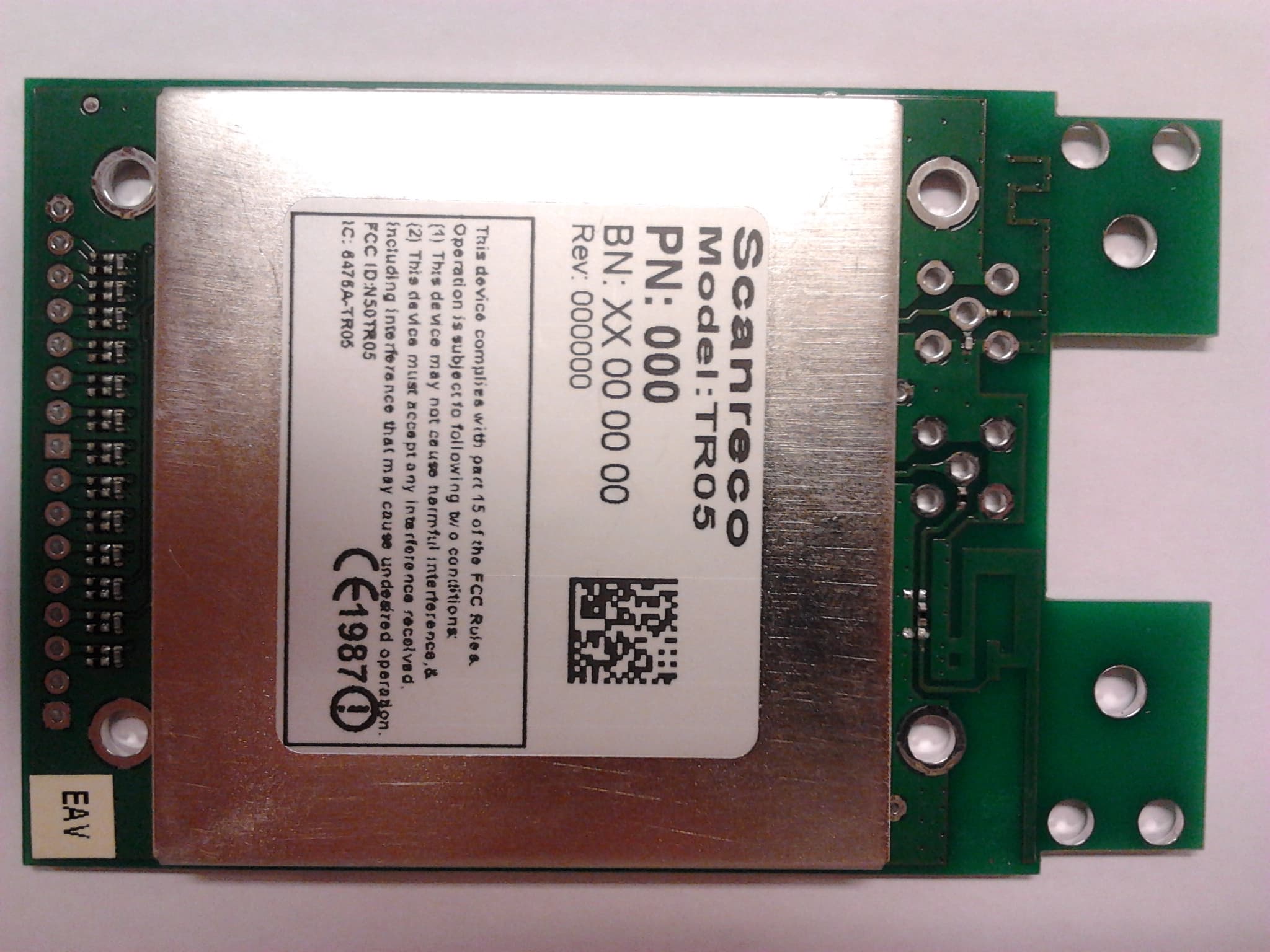
N5OTR05
Sep 02, 20142.4 GHz Transceiver
Equipment Class
DSS - Part 15 Spread Spectrum Transmitter