N5OG5CUM2.4 GHz Transceiver
Scanreco AB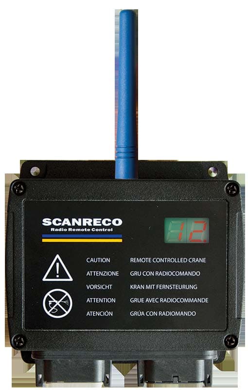
Click to zoom
Application Details
- Equipment Class
- DSS - Part 15 Spread Spectrum Transmitter
- Date of Grant
- May 19, 2014
- Application Purpose
- Original Equipment
- Date of Application
- May 14, 2014
- Equipment Note
- 2.4 GHz Transceiver
- Frequency Range
- 2405.00000000 - 2480.00000000
- Company
- Scanreco AB
- Country
- Sweden
Documents & Files
Document Text
Text extracted from the exhibit documents filed with the FCC. Open a document above to read the original.
Users Manual
Instruction Manual 66064 A English DocumentRevisionLanguage G5 CU M AttributeInformation Document TypeInstruction Manual TitleSCANRECO G5 CU M Document No.66064 LanguageEnglish Release date2013-05-20 OriginalEnglish Release date (original)2013-05-20 AuthorSCANRECO CompanySCANRECO AB, SWEDEN RevisionDateNote A2013-05-20First release Document information Revision history All rights reserved Design, equipment, technical data and specifications are subject to change or improvement without prior notice. The text in this instruction manual, or any part of it may not be reproduced or transmitted in any form or by any means, including electronic, mechanical, photocopying, recording, storage in an information retrieval system, or otherwise, without prior written permis- sion of SCANRECO AB, SWEDEN. Document typeDocument numberPageRev Instruction Manual66064 A 2 of 9 G5 receiver Product description The Central Unit (CU) is manufactured in robust plastic housing and provides contacts for the connection of power supply and electro-hydraulic valves. Several of the outputs can also be used as digital inputs. Depending on the version of the G5 Central unit, it can either be equipped with MOSFET outputs and Deutsch connectors or can have relay outputs with terminal block. Since the central unit can be exposed to very tough environments, the box is encapsulated to give protection from damp, heat, cold, dust, vibration and corrosive environments. The Central unit has short circuit protected inputs and outputs and has protection against reverse polarity, over-voltage, large incoming voltage transients and EMC/RF. Label Document typeDocument numberPageRev Instruction Manual66064 A 3 of 9 MOSFET Digital Output The MOSFET digital outputs are designed to control electro-hydraulic valves but can also be used to load other accessories such as lamps or motors. Digital inputs Estop The digital inputs can be used as a switch to control different functions on the central unit or on the HCU. The maximum input voltage shall not exceed the supply voltage. The Estop function works as a safety function. The output is active each time the HCU is active and communication has been established with the Central unit. This output is normally connected to a dump valve. It is required for the system installer to use this or similar function for the operator safety. The Estop digital output shares the same properties as the other digital outputs. Exspansion boards Description of expansion functionsNumber of exspansion function Analof inputs1-10 Analog outputs1-5 Digital I/O1-20 PWM1-5 The main board may be used stand alone or together with one expansion board. There are several different expansion boards. All expansions boards have the same mechanical outline. They may have different funcionalities depending on customers application. The differnt functions are exemplified in the table below: Document typeDocument numberPageRev Instruction Manual66064 A 4 of 9 Main board Main board with expansion board (49837) Terminal schematics G5-CU M19 Terminal schematics G5-CU M21 1 12 2 11 3 10 4 9 5 8 6 7 7 6 8 5 9 4 10 3 11 2 12 1 1 12 2 11 3 10 4 9 5 8 6 7 7 6 8 5 9 4 10 3 11 2 12 1 1 = Output/input 16 2 = Output/input 15 3 = GND 4 = Output/input 14 5 = Estop 6 = Power Supply + 7 = Output 1 8 = Output 2 9 = Output 3 10 = Output 5 11 = Output 4 12 = Output/input 6 1 = Output/input 16 2 = Output/input 15 3 = GND 4 = Output/input 14 5 = Estop 6 = Power Supply + 7 = Output 1 8 = Output 2 9 = Output 3 10 = Output 5 11 = Output 4 12 = Output/input 6 1 = Output/input 7 2 = Output/input 8 3 = Output/input 9 4 = Output/input 10 5 = Output/input 11 6 = Output/input 12 7 = RS232 TX 8 = RS232 RX 9 = Output/input 13 10 = Output/input 17 11 = Output/input 18 12 = Output/input 19 1 = Output/input 7 2 = Output/input 8 3 = Output/input 9 4 = Output/input 10 5 = Output/input 11 6 = Output/input 12 7 = Mosfet output or 4 - 20 mA input 8 = Mosfet output or 4 - 20 mA input 9 = Output/input 13 10 = Output/input 17 11 = Output/input 18 12 = Output/input 19 Document typeDocument numberPageRev Instruction Manual66064 A 5 of 9 127mm 57mm 186mm 117mm Size: approx. ~ 127 x 117 x 57 mm / ~ 5,0 x 4,6 x 2,2 in. Technical Data Central Unit AttributeInformation Housing materialPlastic PC IP-classIP67 (for versions with cable glands IP65) Ambient temperature-25 ̊C to +70 ̊C Supply voltage9-36VDC FuseNot required. Current consumption at idle<30mA MOSFET Output load3 A, Max simultaneously load for each CU is 10A. Relay Output loadMax 10 A Housing screw torque0,8 Nm WeightApprox. 0,5Kg Document typeDocument numberPageRev Instruction Manual66064 A 6 of 9 AttributeInformation Frequency2,400 - 2,4835 GHz Channels management FHSS DSSS THSS Channel orderPseudorandom Channel capacity Duplex System address/ID <16777216 unique system addresses available RedundancyCRC-16 Range100 meters Technical information The G5 system family incorporates an automated frequency jumping technology, a reliable radio transmission highly resistant to interference. The radio transmission takes place within the ISM-band used at pre-defined channels. The channel switching takes place multiple times per second following a pseudorandom se- quence. This ensures that transmission takes place on an optimal frequency at all times! No transmitter uses the same pseudorandom sequence order when switching channels; this minimizes the risk of two G5 systems interfering with each other. The G5 Pocket is approved to transmit on the ISM band. The radio is license free for the end user. Radio information Document typeDocument numberPageRev Instruction Manual66064 A 7 of 9 This equipment has been tested and found to comply with the limits for a Class A digital device, pursuant to part 15 of the FCC Rules. These limits are designed to provide reasonable protection against harmful interference when the equipment is operated in a commercial environment. This equipment generates,uses, and can radiate radio frequency energy …
Text truncated - open the document above for the full version.
Cover Letter(s)
Postal adressTelephone+46 8 556 32 800VAT NoSE556245004801 Box 47144/Årsta Skolgränd 22Telefax+46 8 556 32 828Org No556245-0048 SE-100 74 Stockholm, [email protected] Attention: Application Examiner Re:Request for confidentiality Applicant: Scanreco Industrielektronik AB FCC ID: N5OG5CUM Product Name:G5 CU M19, G5 CU M21 To whom it may concern, Permanent Confidentiality Request is hereby submitted by Scanreco Industrielektronik AB to withhold permanently from public review certain portions of the application for equipment certification for the referenced FCC identifiers. This request for confidentiality is made pursuant to 47 CFR 0.457(d) and 0.459 of the FCC Rules. In particular, the following sections of the application are to be kept permanently confidential: • Schematics • Detailed Block diagrams • Detailed Operational/Functional Description • Parts list • Internal photos - since this is non-consumer device serviceable only by designated tech. Rationale for request for confidentiality: Scanreco Industrielektronik AB has invested considerable time and materials in research and development to produce the referenced product. Disclosure of the permanently confidential portions of this application to competitors would not only give them significant competitive advantages in developing similar products, but would also disclose successful implementation of unpublished, leading edge technology developed by us. If you have questions or need further information, please contact the undersigned. Stockholm, Sweden, 2014-02-04 Sincerely, Andrei Sazonov, PhD Senior RF Specialist Scanreco Industrielektronik AB
ID Label/Location Info
Postal adressTelephone+46 8 556 32 800VAT NoSE556245004801 Box 47144/Årsta Skolgränd 22Telefax+46 8 556 32 828Org No556245-0048 SE-100 74 Stockholm, [email protected] G5 CU M Label Format and Location Postal adressTelephone+46 8 556 32 800VAT NoSE556245004801 Box 47144/Årsta Skolgränd 22Telefax+46 8 556 32 828Org No556245-0048 SE-100 74 Stockholm, [email protected] 32 mm 22.5 mm
Test Report
SORT OF EQUIPMENT: 2.4 GHz Transceiver TRADE MARK: TYPE: MANUFACTURER: CLIENT: Scanreco Industrielektronik AB ADDRESS: Årsta Skolgränd 22, S – 100 74 Stockholm, Sweden TEST LABORATORY: Nemko Oy FCC REG. NO. 359859 October 20, 2011 IC FILE NO. 2040F-1 November 22, 2012 Nemko Oy P.O.Box 19, FI-02601 Espoo, Finland Street address: Perkkaantie 11, FI-02600 Espoo Telephone +358 (0)424 5454 1 Telefax +358 (0)9 5489 6371 SUMMARY: Only the type of G5 P8A was tested since the electrical circuit design, layout, components used and internal wiring were identical for all types of the product. In regard to the performed tests the equipment under test fulfils the requirements defined in the test specifications, see page 2 for details. The test results are valid for the tested unit only. Without a written permission of Nemko Oy it is allowed to copy this report as a whole, but not partially. TEST REPORT Date: ESPOO 02.10.2013 Page: 1 (29) Appendices Date of handing in: 23.11.2012 Number: No. 1 / 1 224568H Tested by: Pekka Kälviäinen, Test Engineer Reviewed by: Timo Leismala, Test Manager SCANRECO G5 P1, G5 P2, G5 P3, G5 P4, G5 P, G5 P7, G5 P7, G5 P8 Scanreco Industrielektronik AB Version f1.00 Type: G5 Test report: 224568H 2 (29) 02.10.2013 Page Date Summary of performed tests and test results Section in CFR 47 Section in RSS-GEN or RSS-210, Issue 8 Result 15.247 (b)(1) A8.4 (2) Conducted peak output power PASS 15.247 (d) A8.5 Band-edge compliance of RF emissions PASS 15.247 (d) A8.5 Spurious RF conducted emissions PASS 15.247 (d) 15.209 A8.5 Spurious radiated emissions PASS 15.207 7.2.2 AC power line conducted emissions N.A. 15.247 (a)(1) A8.1 (a) 20 dB bandwidth X 15.247 (a)(1) A8.1 (b) Carrier frequency separation PASS 15.247 (a)(1)(iii) A8.1 (d) Number of hopping frequencies PASS 15.247 (a)/1)(iii) A8.1 (d) Time of occupancy PASS Explanations: PASS The EUT passed that particular test. FAIL The EUT failed that particular test. N.A. The test not applicable, battery operated equipment X The measurement was done, but there is no applicable performance criteria. Type: G5 Test report: 224568H 3 (29) 02.10.2013 Page Date Contents Summary of performed tests and test results ........................................................................................... 2 1. EUT and Accessory Information ......................................................................................................... 4 1.1 EUT description ........................................................................................................................ 4 1.2 EUT and accessories ................................................................................................................ 4 1.3 Additional information related to testing.................................................................................... 4 2. Test setups .......................................................................................................................................... 5 3. Standards and measurement methods ............................................................................................... 6 4. Test results .......................................................................................................................................... 6 4.1 Conducted peak output power .................................................................................................. 6 4.1.1 EUT operation mode ................................................................................................................. 6 4.1.2 Test method and limit ................................................................................................................ 6 4.1.3 Test results................................................................................................................................ 6 4.2 Band-edge compliance of RF emissions .................................................................................. 8 4.2.1 EUT operation mode ................................................................................................................. 8 4.2.2 Test method and limit ................................................................................................................ 8 4.2.3 Test results................................................................................................................................ 9 4.3 Spurious RF conducted emission ........................................................................................... 12 4.3.1 EUT operation mode ............................................................................................................... 12 4.3.2 Test method and limit .............................................................................................................. 12 4.3.3 Test results.............................................................................................................................. 12 4.4 Spurious radiated emission ..................................................................................................... 16 4.4.1 EUT operation mode ............................................................................................................... 16 4.4.2 Test method and limit .............................................................................................................. 16 4.4.3 Test results.............................................................................................................................. 18 4.5 20 dB bandwidth ..................................................................................................................... 19 4.5.1 EUT operation mode ............................................................................................................... 19 4.5.2 Test method and limit .............................................................................................................. 19 4.5.3 Test results...........…
Text truncated - open the document above for the full version.
Test Report
Timo Hietala, Test Specialist Janne Nyman, compliance specialist SORT OF EQUIPMENT: 2.4 GHz Transceiver TRADE MARK: TYPE: MANUFACTURER: CLIENT: Scanreco Industrielektronik AB ADDRESS: Årsta Skolgränd 22, S – 100 74 Stockholm, Sweden TEST LABORATORY: Nemko Oy FCC REG. NO. 359859 October 20, 2011 IC FILE NO. 2040F-1 November 22, 2012 Nemko Oy P.O.Box 19, FI-02601 Espoo, Finland Street address: Perkkaantie 11, FI-02600 Espoo Telephone +358 (0)424 5454 1 Telefax +358 (0)9 5489 6371 SUMMARY: In regard to the performed tests the equipment under test fulfils the requirements defined in the test specifications, see page 2 for details. The test results are valid for the tested unit only. Without a written permission of Nemko Oy it is allowed to copy this report as a whole, but not partially. Date: ESPOO 04.10.2013 Page: 1 (30) Appendices Date of handing in: 30.09.2013 Number: No. 1 / 1 245598A Tested by: Reviewed by: SCANRECO G5 CU M Scanreco Industrielektronik AB Version f1.00 Type: G5 CU M Test report: 245598A Page Date 2 (30) 04.10.2013 Summary of performed tests and test results Section in CFR 47 Section in RSS-GEN or RSS-210, Issue 8 Result 15.247 (b)(1) A8.4 (2) Conducted peak output power PASS 15.247 (d) A8.5 Band-edge compliance of RF emissions PASS 15.247 (d) A8.5 Spurious RF conducted emissions *) 15.247 (d) 15.209 A8.5 Spurious radiated emissions PASS 15.207 7.2.2 AC power line conducted emissions PASS 15.247 (a)(1) A8.1 (a) 20 dB bandwidth *). 15.247 (a)(1) A8.1 (b) Carrier frequency separation *) 15.247 (a)(1)(iii) A8.1 (d) Number of hopping frequencies *) 15.247 (a)/1)(iii) A8.1 (d) Time of occupancy *). *) Test results in test report no. 224568 FCC 15.247 TRF RAD rev2. PASS The EUT passed that particular test. FAIL The EUT failed that particular test. N.A. The test not applicable, battery operated equipment X The measurement was done, but there is no applicable performance criteria. N.T. Not Tested Type: G5 CU M Test report: 245598A Page Date 3 (30) 04.10.2013 Contents Summary of performed tests and test results ........................................................................................... 2 1. EUT and Accessory Information ......................................................................................................... 4 1.1 EUT description ........................................................................................................................ 4 1.2 EUT and accessories ................................................................................................................ 4 1.3 Additional information related to testing ................................................................................... 4 2. Test setups .......................................................................................................................................... 5 3. Standards and measurement methods ............................................................................................... 6 4. Test results .......................................................................................................................................... 6 4.1 Conducted peak output power .................................................................................................. 6 4.1.1 EUT operation mode ................................................................................................................. 6 4.1.2 Test method and limit................................................................................................................ 6 4.1.3 Test results ............................................................................................................................... 6 4.2 Band-edge compliance of RF emissions .................................................................................. 9 4.2.1 EUT operation mode ................................................................................................................. 9 4.2.1 Test method and limit................................................................................................................ 9 4.2.2 Test results ............................................................................................................................. 10 4.3 Spurious radiated emission..................................................................................................... 18 4.3.1 EUT operation mode ............................................................................................................... 18 4.3.2 Test method and limit.............................................................................................................. 18 4.3.3 Test results ............................................................................................................................. 20 4.3.4 Test results, Radiated emissions in restricted bands 30 MHz – 25 GHz ................................ 20 4.4 Duty cycle correction factor ..................................................................................................... 24 4.5 AC power line conducted emissions ....................................................................................... 25 4.5.1 Test method and limit.............................................................................................................. 25 4.5.2 EUT operation mode ............................................................................................................... 25 4.5.3 Test results ............................................................................................................................. 26 5. List of test equipment ........................................................................................................................ 28 6. Photographs ...................................................................................................................................... 29 Type: G5 CU M Test report: 245598A Page Date 4 …
Text truncated - open the document above for the full version.
Contact Information
Applicant
Bjorn Askestig(Vice President)
Technical Contact
Test Firm
NEMKO OyJyrki Leino
Technical Specifications
| # | Rule Parts | Frequency Range | Power Output |
|---|---|---|---|
| 1 | 15C | 2.40 GHz - 2.48 GHz | 71.10 mW |
Other Applications from Scanreco AB
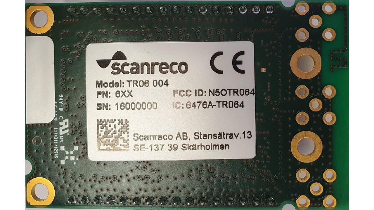
N5OTR064
Apr 25, 2021TR06 Transceiver Module
Equipment Class
DTS - Digital Transmission SystemN5OD3DRCJ
Apr 21, 20202.4 GHz Transceiver
Equipment Class
DSS - Part 15 Spread Spectrum TransmitterN5OD3DRCMP
Feb 03, 20202.4 GHz Transceiver
Equipment Class
DSS - Part 15 Spread Spectrum Transmitter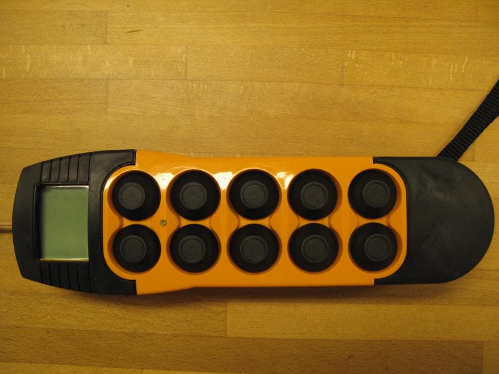
N5OD3DRC10
Aug 26, 20152.4 GHz Transceiver Model Number DRC-10 D3, DRC-10 2ST D3
Equipment Class
DSS - Part 15 Spread Spectrum Transmitter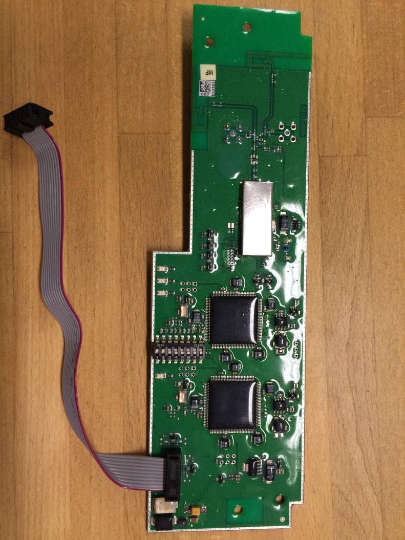
N5OD3DRCDRBM
Aug 25, 2015DRC-DR D3, DRC-BM D3
Equipment Class
DSS - Part 15 Spread Spectrum Transmitter