N5OG5RF2.4 GHz Transceiver
Scanreco AB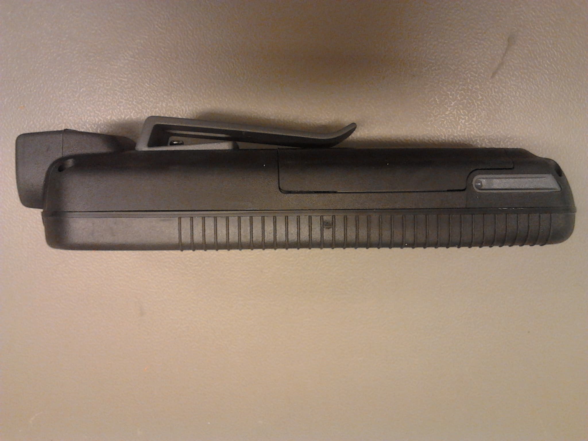
Click to zoom
Application Details
- Equipment Class
- DSS - Part 15 Spread Spectrum Transmitter
- Date of Grant
- Jun 25, 2014
- Application Purpose
- Original Equipment
- Date of Application
- May 14, 2014
- Equipment Note
- 2.4 GHz Transceiver
- Frequency Range
- 2405.00000000 - 2480.00000000
- Company
- Scanreco AB
- Country
- Sweden
Documents & Files
Document Text
Text extracted from the exhibit documents filed with the FCC. Open a document above to read the original.
Users Manual
Instruction Manual 66065 A English DocumentRevisionLanguage G5 RF AttributeInformation Document TypeInstruction Manual TitleSCANRECO G5 Rocket Flex Document No.66065 LanguageEnglish Release date2013-10-16 OriginalEnglish Release date (original)2013-10-16 AuthorSCANRECO CompanySCANRECO AB, SWEDEN RevisionDateNote A2013-10-16First release Document information Revision history All rights reserved Design, equipment, technical data and specifications are subject to change or improvement without prior notice. The text in this instruction manual, or any part of it may not be reproduced or transmitted in any form or by any means, including electronic, mechanical, photocopying, recording, storage in an information retrieval system, or otherwise, without prior written permis- sion of SCANRECO AB, SWEDEN. Document typeDocument numberPageRev Instruction Manual66065 A 2 of 8 Product description G5 Rocket Flex Transmitter The G5 Rocket Flex HCU is a light weight, impact and water resistant handheld unit equipped with up to fourteen ON/OFF function buttons. It has six configurable Light Emitting Diodes (LED) for machine and status feedback. The buttons and the LED’s can be configured for a variety of different operations. The unit is powered with 3 standard AAA batteries and the backside has a belt clip for convenient at- tachment on the operator’s belt. Belt clip Battery compartment (Belt clip removed) Battery compartment (cover removed) Label Charge indication Stop button Button 1Button 2 Button 3Button 4 Button 5Button 6 Button 7Button 8 Button 9Button 10 Button 11Button 12 Button 13 Button 14 Led 3 Led 2Led 4 Led 1Led 5 Document typeDocument numberPageRev Instruction Manual66065 A 3 of 8 ModelFunctions G5 RF 1010 Push buttons G5 RF 1212 Push buttons G5 RF 1414 Push buttons G5 RF 10 Display10 Push buttons G5 RF 12 Display12 Push buttons G5 RF 14 Display14 Push buttons Versions The G5 Rocket Flex transmitter exists in the following versions: Functionality G5 RF 10G5 RF 12G5 RF 14G5 RF 10 DisplayG5 RF 12 DisplayG5 RF 14 Display The G5 Rocket-Flex systems are required to be configured prior to operation but normally this is done already before delivery. The push buttons are easily programmed to activate any output or series of functions. Button definitions include momentary, interlocked, non-latched or latched output. The models may have the different printed symbols on the buttons, colors, scripts, pictures etc. Document typeDocument numberPageRev Instruction Manual66065 A 4 of 8 48mm 42,2mm 213mm 69mm AttributeInformation Housing materialPlastic PC IP-classIP67 Ambient temperature-25 ̊C to +70 ̊C Supply3 x AA battery Operating timeSeveral months (depending of usage and application) Weight400g (0,88lb.) including battery ISO-13849 for stop functionCategory 3, PL D with G5 CU Rxxx Category 3, PL E with G5 CU Mxxx Dimensions: 34,7mm 83,5mm Technical information Document typeDocument numberPageRev Instruction Manual66065 A 5 of 8 AttributeInformation Frequency2,400 - 2,4835 GHz Channels management FHSS DSSS THSS Channel orderPseudorandom Channel capacity Duplex System address/ID <16777216 unique system addresses available RedundancyCRC-16 Range100 meters Technical information The G5 system family incorporates an automated frequency jumping technology, a reliable radio transmission highly resistant to interference. The radio transmission takes place within the ISM-band used at pre-defined channels. The channel switching takes place multiple times per second following a pseudorandom se- quence. This ensures that transmission takes place on an optimal frequency at all times! No transmitter uses the same pseudorandom sequence order when switching channels; this minimizes the risk of two G5 systems interfering with each other. The G5 Rocket-Flex is approved to transmit on the ISM band. The radio is license free for the end user. Radio information Document typeDocument numberPageRev Instruction Manual66065 A 6 of 8 Document typeDocument numberPageRev Instruction Manual66065 A 7 of 8zz This equipment has been tested and found to comply with the limits for a Class A digital device, pursuant to part 15 of the FCC Rules. These limits are designed to provide reasonable protection against harmful interference when the equipment is operated in a commercial environment. This equipment generates,uses, and can radiate radio frequency energy and, if not installed and used in accordance with the instruction manual, may cause harmful interference to radio communications. Operation of this equipment in a residential area is likely to cause harmful interference in which case the user will be required to correct the interference at his own expense. This device complies with part 15 of the FCC Rules. Operation is subject to the following two conditions: (1) This device may not cause harmful interference, and (2) this device must accept any interference received, including interference that may cause undesired operation. This device complies with Industry Canada licence-exempt RSS standard(s). Operation is subject to the following two conditions: (1) this device may not cause interference, and (2) this device must accept any interference, including interference that may cause undesired operation of the device. Le présent appareil est conforme aux CNR d’Industrie Canada applicables aux appareils radio exempts de licence. L’exploitation est autorisée aux deux conditions suivantes : (1) l’appareil ne doit pas produire de brouillage, et (2) l’utilisateur de l’appareil doit accepter tout brouillage radioélectrique subi, même si le brouillage est susceptible d’en compromettre le fonctionnement. CAN ICES-3 (A)/NMB-3(A) The antenna(s) used for this transmitter must be installed to provide a separation distance of at least 20 cm from all persons and must not be co-located or operating in conjunction with any other antenna or transmitter. When the device is stored on the operators belt it must be shut off. Pressing the buttons and operat…
Text truncated - open the document above for the full version.
Attestation Statements
Postal adressTelephone+46 8 556 32 800VAT NoSE556245004801 Box 47144/Årsta Skolgränd 22Telefax+46 8 556 32 828Org No556245-0048 SE-100 74 Stockholm, [email protected] G5 RF Attestation Letter Product:2,4 GHz Transceiver G5 RF10, G5 RF12, G5 RF14, G5 RF10 Display, G5 RF12 Display, G5 RF14 Display Company:ScanrecoIndustrielektronik AB, Box 47144/ÅrstaSkolgränd 22, S-10074, Stockholm, Sweden Hereby declares that the devices G5 RF10, G5 RF12, G5 RF14, G5 RF10 Display, G5 RF12 Display, G5 RF14 Display are incapable of transmitting higher than the duty factor supported by the information provided in the equipment certification filing: maximum 72,36% duty cycle. June 04, 2014 Andrei Sazonov, PhD Senior RF Specialist
Cover Letter(s)
Postal adressTelephone+46 8 556 32 800VAT NoSE556245004801 Box 47144/Årsta Skolgränd 22Telefax+46 8 556 32 828Org No556245-0048 SE-100 74 Stockholm, [email protected] G5 RF Model Differences Letter Models G5 RF10, G5 RF12, G5 RF14, G5 RF10 Display, G5 RF12 Display, G5 RF14 Display have the same schematics and pcb layout. The only differences are different number of buttons mounted and not mounted display for models G5 RF10, G5 RF12, G5 RF14. The numbers 10, 12, 14 indicate a number of buttons used (see, for example, the picture below). The models may have the different printed symbols on the buttons, colors, scripts, pictures etc. used.
ID Label/Location Info
Postal adressTelephone+46 8 556 32 800VAT NoSE556245004801 Box 47144/Årsta Skolgränd 22Telefax+46 8 556 32 828Org No556245-0048 SE-100 74 Stockholm, [email protected] G5 RF Label Format and Location Postal adressTelephone+46 8 556 32 800VAT NoSE556245004801 Box 47144/Årsta Skolgränd 22Telefax+46 8 556 32 828Org No556245-0048 SE-100 74 Stockholm, [email protected] 32 mm 22.5mm
RF Exposure Info
Postal adressTelephone+46 8 556 32 800VAT NoSE556245004801 Box 47144/Årsta Skolgränd 22Telefax+46 8 556 32 828Org No556245-0048 SE-100 74 Stockholm, [email protected] G5 RF SAR exclusion analysis Product:2,4 GHz Transceiver G5 RF10, G5 RF12, G5 RF14, G5 RF10 Display, G5 RF12 Display, G5 RF14 Display Company:ScanrecoIndustrielektronik AB, Box 47144/ÅrstaSkolgränd 22, S-10074, Stockholm, Sweden The radio part in this device is used in other hand-held / hand-operated devices and in equipment that is permanently installed to provide a separation distance of at least 20 cm from the user. In this hand-held / hand-operated device the antenna to extremity separation distance is at least 40 mm. The distance from the user to the antenna is at least 20 cm. Therefore body SAR is not required. The maximum duty cycle is 72,36%. The duty cycle is hardly coded in the firmware under production and cannot be changed by the user. Extremity SAR exclusion based on 40 mm separation distance and 72,36% maximum duty cycle is documented below. 20 cm Postal adressTelephone+46 8 556 32 800VAT NoSE556245004801 Box 47144/Årsta Skolgränd 22Telefax+46 8 556 32 828Org No556245-0048 SE-100 74 Stockholm, [email protected] Minimum test separation distance “d”: see 4.3.1 of 447498 “The minimum test separation distance is determined by the smallest distance from the antenna and radiating structures or outer surface of the device, according to the host form factor, exposure conditions and platform requirements, to any part of the body or extremity of a user or bystander (see 5) of section 4.1).” The closest distance from the antenna to the users hand is 45,81mm (see picture below). When the device is stored on the operators belt it must be shut off. Pressing the buttons and operating the machine while the device is hanging from the belt or any other place it not allowed. It must be held in the hand. The closest distance from the antenna to the users hand is 45,81 mm Postal adressTelephone+46 8 556 32 800VAT NoSE556245004801 Box 47144/Årsta Skolgränd 22Telefax+46 8 556 32 828Org No556245-0048 SE-100 74 Stockholm, [email protected] The device has the duty cycle max 72,36%. From the picture below the duty cycle: (4,32ms/95,5ms)*16channels = 72,36% Postal adressTelephone+46 8 556 32 800VAT NoSE556245004801 Box 47144/Årsta Skolgränd 22Telefax+46 8 556 32 828Org No556245-0048 SE-100 74 Stockholm, [email protected] The Rated output power is 19,5dBm. The tune up tolerance is 0,5dB. The internal antenna gain is 0dBi. SAR evaluation – exemption limits for routine routine evaluation based on frequency and separation distance at 2450 MHz, 10 mm, extremity = 7 x 2.5 = 17.5 mW FCC extremity SAR exemptioncalculations as per section 4.3.1 of “447498 D01 General RF Exposure Guidance v05r02”: The equipment meets the FCC SAR exemption limits and SAR measurement is not required. Postal adressTelephone+46 8 556 32 800VAT NoSE556245004801 Box 47144/Årsta Skolgränd 22Telefax+46 8 556 32 828Org No556245-0048 SE-100 74 Stockholm, [email protected] RSS-102 exemption Notice_2013DRS0911 Extremity SAR Evaluation: SAR evaluation – exemption limits for routine evaluation based on frequency and separation distance at 2450 MHz, 40 mm, extremity = 173 x 2.5 = 432.5 mW The EIRP meets the RSS-102 exemption limits in “Notice_2013DRS0911”. Postal adressTelephone+46 8 556 32 800VAT NoSE556245004801 Box 47144/Årsta Skolgränd 22Telefax+46 8 556 32 828Org No556245-0048 SE-100 74 Stockholm, [email protected] Conclusion:The product satisfies the OET Bulletin 65 Edition 97-1 and RSS- 102 Notice 2013_DRS0911. June 04, 2014 Andrei Sazonov, PhD Senior RF Specialist
Test Report
SORT OF EQUIPMENT: 2.4 GHz Transceiver TRADE MARK: TYPE: MANUFACTURER: CLIENT: Scanreco Industrielektronik AB ADDRESS: Årsta Skolgränd 22, S – 100 74 Stockholm, Sweden TEST LABORATORY: Nemko Oy FCC REG. NO. 359859 October 20, 2011 IC FILE NO. 2040F-1 November 22, 2012 Nemko Oy P.O.Box 19, FI-02601 Espoo, Finland Street address: Perkkaantie 11, FI-02600 Espoo Telephone +358 (0)424 5454 1 Telefax +358 (0)9 5489 6371 SUMMARY: Only the type of G5 P8A was tested since the electrical circuit design, layout, components used and internal wiring were identical for all types of the product. In regard to the performed tests the equipment under test fulfils the requirements defined in the test specifications, see page 2 for details. The test results are valid for the tested unit only. Without a written permission of Nemko Oy it is allowed to copy this report as a whole, but not partially. TEST REPORT Date: ESPOO 02.10.2013 Page: 1 (29) Appendices Date of handing in: 23.11.2012 Number: No. 1 / 1 224568H Tested by: Pekka Kälviäinen, Test Engineer Reviewed by: Timo Leismala, Test Manager SCANRECO G5 P1, G5 P2, G5 P3, G5 P4, G5 P, G5 P7, G5 P7, G5 P8 Scanreco Industrielektronik AB Version f1.00 Type: G5 Test report: 224568H 2 (29) 02.10.2013 Page Date Summary of performed tests and test results Section in CFR 47 Section in RSS-GEN or RSS-210, Issue 8 Result 15.247 (b)(1) A8.4 (2) Conducted peak output power PASS 15.247 (d) A8.5 Band-edge compliance of RF emissions PASS 15.247 (d) A8.5 Spurious RF conducted emissions PASS 15.247 (d) 15.209 A8.5 Spurious radiated emissions PASS 15.207 7.2.2 AC power line conducted emissions N.A. 15.247 (a)(1) A8.1 (a) 20 dB bandwidth X 15.247 (a)(1) A8.1 (b) Carrier frequency separation PASS 15.247 (a)(1)(iii) A8.1 (d) Number of hopping frequencies PASS 15.247 (a)/1)(iii) A8.1 (d) Time of occupancy PASS Explanations: PASS The EUT passed that particular test. FAIL The EUT failed that particular test. N.A. The test not applicable, battery operated equipment X The measurement was done, but there is no applicable performance criteria. Type: G5 Test report: 224568H 3 (29) 02.10.2013 Page Date Contents Summary of performed tests and test results ........................................................................................... 2 1. EUT and Accessory Information ......................................................................................................... 4 1.1 EUT description ........................................................................................................................ 4 1.2 EUT and accessories ................................................................................................................ 4 1.3 Additional information related to testing.................................................................................... 4 2. Test setups .......................................................................................................................................... 5 3. Standards and measurement methods ............................................................................................... 6 4. Test results .......................................................................................................................................... 6 4.1 Conducted peak output power .................................................................................................. 6 4.1.1 EUT operation mode ................................................................................................................. 6 4.1.2 Test method and limit ................................................................................................................ 6 4.1.3 Test results................................................................................................................................ 6 4.2 Band-edge compliance of RF emissions .................................................................................. 8 4.2.1 EUT operation mode ................................................................................................................. 8 4.2.2 Test method and limit ................................................................................................................ 8 4.2.3 Test results................................................................................................................................ 9 4.3 Spurious RF conducted emission ........................................................................................... 12 4.3.1 EUT operation mode ............................................................................................................... 12 4.3.2 Test method and limit .............................................................................................................. 12 4.3.3 Test results.............................................................................................................................. 12 4.4 Spurious radiated emission ..................................................................................................... 16 4.4.1 EUT operation mode ............................................................................................................... 16 4.4.2 Test method and limit .............................................................................................................. 16 4.4.3 Test results.............................................................................................................................. 18 4.5 20 dB bandwidth ..................................................................................................................... 19 4.5.1 EUT operation mode ............................................................................................................... 19 4.5.2 Test method and limit .............................................................................................................. 19 4.5.3 Test results...........…
Text truncated - open the document above for the full version.
Test Report
Nemko Oy P.O.Box 19, FI-02601 Espoo, Finland Street address: Perkkaantie 11, FI-02600 Espoo Telephone +358 (0)424 5454 1 Telefax +358 (0)9 5489 6371 Date: ESPOO 21.11.2013 Page: 1 (19) Appendices Date of handing in: 11.11.2013 Number: 248340 No. 1 / 1 Tested by: Pekka Kälviäinen, Test Specialist Reviewed by: Janne Nyman, compliance specialist SORT OF EQUIPMENT: 2.4 GHz Transceiver TRADE MARK: SCANRECO TYPE: G5 RF10, G5 RF10 Display, G5 RF12, G5 RF12 Display, G5 RF14, G5 RF14 Display MANUFACTURER: Scanreco Industrielektronik AB CLIENT: Scanreco Industrielektronik AB ADDRESS: Årsta Skolgränd 22, S – 100 74 Stockholm, Sweden TEST LABORATORY: Nemko Oy FCC REG. NO. 359859 October 25, 2013 IC FILE NO. 2040F-1 November 22, 2012 SUMMARY: In regard to the performed tests the equipment under test fulfils the requirements defined in the test specifications, see page 2 for details. The test results are valid for the tested unit only. Without a written permission of Nemko Oy it is allowed to copy this report as a whole, but not partially. Version f1.00 Type: G5 RF10, G5 RF10 Display, G5 RF12, G5 RF12 Display, G5 RF14, G5 RF14 Display Test report: 248340 Page 2 (19) Date 21.11.2013 Summary of performed tests and test results Section in CFR 47 Section in RSS-GEN or RSS-210, Issue 8 Result 15.247 (b)(1) A8.4 (2) Conducted peak output power PASS 15.247 (d) A8.5 Band-edge compliance of RF emissions PASS 15.247 (d) A8.5 Spurious RF conducted emissions *) 15.247 (d) 15.209 A8.5 Spurious radiated emissions PASS 15.207 7.2.2 AC power line conducted emissions N.A. 15.247 (a)(1) A8.1 (a) 20 dB bandwidth *) 15.247 (a)(1) A8.1 (b) Carrier frequency separation *) 15.247 (a)(1)(iii) A8.1 (d) Number of hopping frequencies *). 15.247 (a)/1)(iii) A8.1 (d) Time of occupancy *) *) Test results in test report no. 224568 FCC 15.247 TRF RAD rev2. PASS The EUT passed that particular test. FAIL The EUT failed that particular test. N.A. The test not applicable, battery operated equipment X The measurement was done, but there is no applicable performance criteria. Type: G5 RF10, G5 RF10 Display, G5 RF12, G5 RF12 Display, G5 RF14, G5 RF14 Display Test report: 248340 Page 3 (19) Date 21.11.2013 Contents Summary of performed tests and test results .......................................................................................... 2 1. EUT and Accessory Information ......................................................................................................... 4 1.1 EUT description ........................................................................................................................ 4 1.2 EUT and accessories ................................................................................................................ 4 1.3 Additional information related to testing ................................................................................... 4 2. Test setups .......................................................................................................................................... 5 3. Standards and measurement methods ............................................................................................... 6 4. Test results .......................................................................................................................................... 6 4.1 Conducted peak output power .................................................................................................. 6 4.1.1 EUT operation mode ................................................................................................................. 6 4.1.2 Test method and limit ............................................................................................................... 6 4.1.3 Test results ............................................................................................................................... 6 4.2 Band-edge compliance of RF emissions .................................................................................. 9 4.2.1 EUT operation mode ................................................................................................................. 9 4.2.1 Test method and limit ............................................................................................................... 9 4.2.2 Test results ............................................................................................................................. 10 4.3 Spurious radiated emission .................................................................................................... 13 4.3.1 EUT operation mode ............................................................................................................... 13 4.3.2 Test method and limit ............................................................................................................. 13 4.3.3 Test results ............................................................................................................................. 15 4.3.4 Test results, Radiated emissions in restricted bands 30 MHz – 25 GHz ............................... 15 4.4 Duty cycle correction factor .................................................................................................... 17 5. List of test equipment ........................................................................................................................ 18 6. Photographs ...................................................................................................................................... 19 Type: G5 RF10, G5 RF10 Display, G5 RF12, G5 RF12 Display, G5 RF14, G5 RF14 Display Test report: 248340 Page 4 (19) Date 21.11.2013 1. EUT and Accessory Information 1.1 EUT description 2.4 GHz transceiver, Frequency hopping system, 16 channels Type: G5 RF10, G5 RF10 Display, G5 RF12, G5 RF12 Display, G5 RF14, G5 RF14 Display 1.2 EUT and accessories unit type s/n EUT1 Transceiver with temporary antenna connector (SM…
Text truncated - open the document above for the full version.
Test Setup Photos
G5 RF Test Setup
Contact Information
Applicant
Bjorn Askestig(Vice President)
Technical Contact
Test Firm
NEMKO OyJyrki Leino
Technical Specifications
| # | Rule Parts | Frequency Range | Power Output |
|---|---|---|---|
| 1 | 15C | 2.40 GHz - 2.48 GHz | 84.10 mW |
Other Applications from Scanreco AB
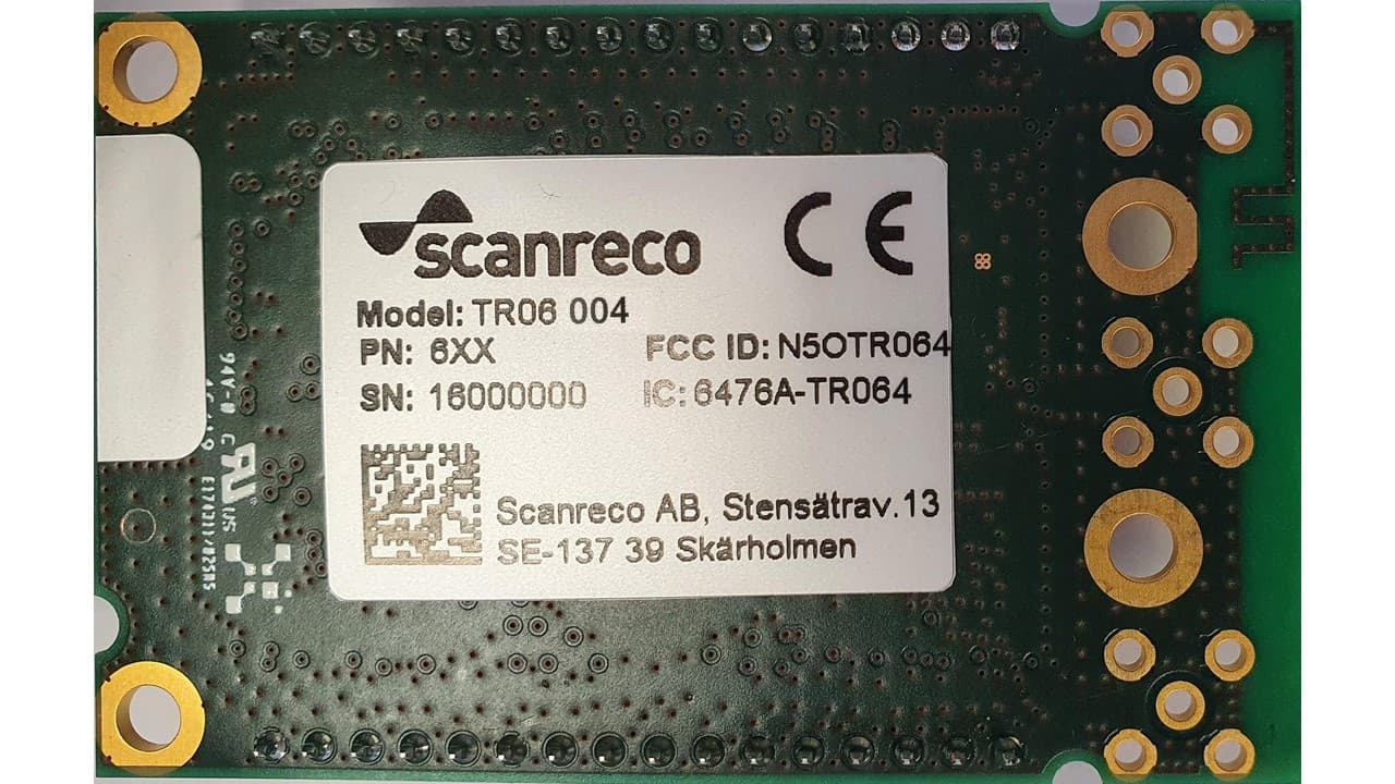
N5OTR064
Apr 25, 2021TR06 Transceiver Module
Equipment Class
DTS - Digital Transmission SystemN5OD3DRCJ
Apr 21, 20202.4 GHz Transceiver
Equipment Class
DSS - Part 15 Spread Spectrum TransmitterN5OD3DRCMP
Feb 03, 20202.4 GHz Transceiver
Equipment Class
DSS - Part 15 Spread Spectrum Transmitter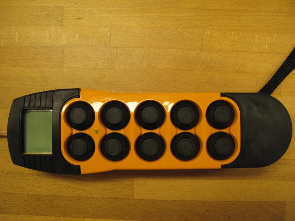
N5OD3DRC10
Aug 26, 20152.4 GHz Transceiver Model Number DRC-10 D3, DRC-10 2ST D3
Equipment Class
DSS - Part 15 Spread Spectrum Transmitter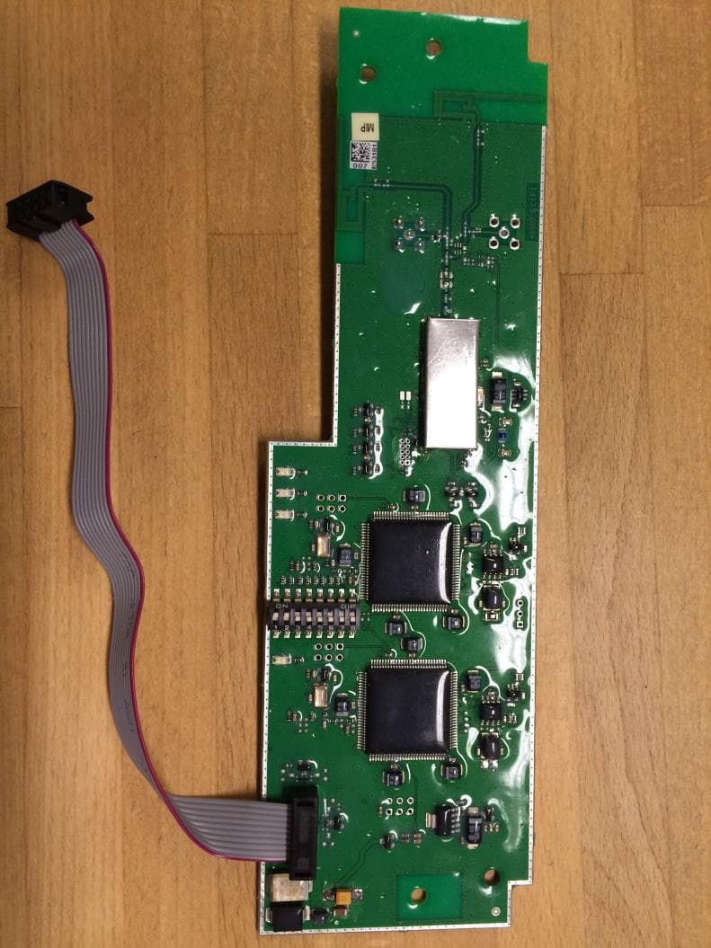
N5OD3DRCDRBM
Aug 25, 2015DRC-DR D3, DRC-BM D3
Equipment Class
DSS - Part 15 Spread Spectrum Transmitter