N5ORC917FHLTR02Radio Remote Control Module
Scanreco AB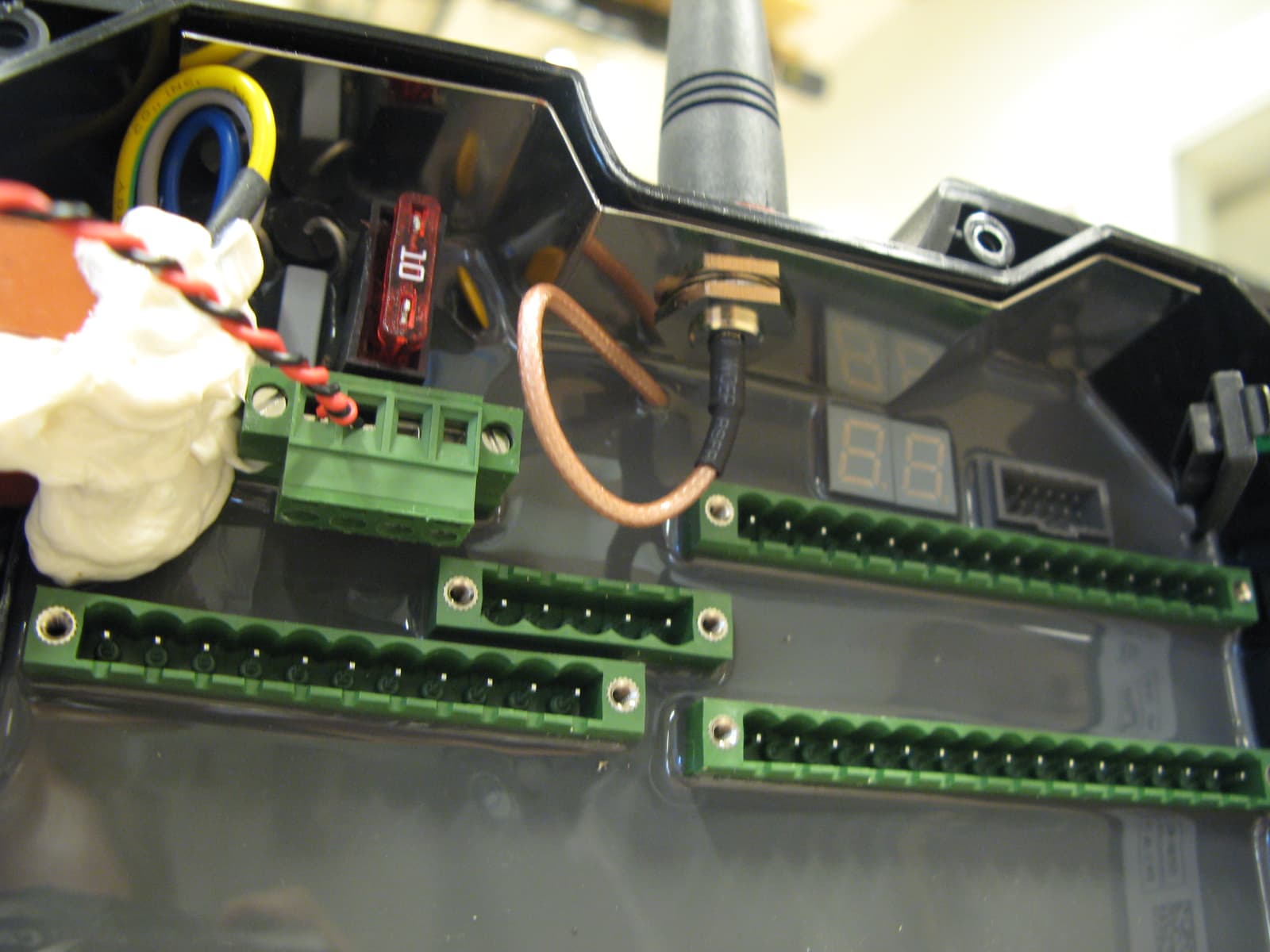
Click to zoom
Application Details
- Equipment Class
- DSS - Part 15 Spread Spectrum Transmitter
- Date of Grant
- Jul 17, 2012
- Application Purpose
- Original Equipment
- Date of Application
- Jul 17, 2012
- Equipment Note
- Radio Remote Control Module
- Frequency Range
- 902.05000000 - 927.95000000
- Company
- Scanreco AB
- Country
- Sweden
Documents & Files
Document Text
Text extracted from the exhibit documents filed with the FCC. Open a document above to read the original.
Users Manual
R C 9 1 7 / T R 0 2 U s e r m a n u a l a n d u p g r a d e i n s t r u c t i o n D e v e l o p e d f o r d e m a n d i n g e n v i r o n m e n t s Scanreco ́s RC917 / TR02 is built and designed for the toughest and most demanding of environments. Scanreco can hereby offer the market of crane and machine operators an extremely easy to use radio remote control retaining speed, precision, and control with the maximum of safety. Behind the development of the radio transceivers lies the idea of providing a product with a high degree of reliability, user-friendliness, and easy upgrade for cable systems or other data radio applications. The product family includes different transceivers and receivers offering a variety of choice depending on the area of use. These products are based on a modular architecture, which makes them extremely flexible to customize and adapt according to the customer’s needs. The products – which are in high demand – are mainly mounted on cranes and mobile machines. Our customers are some of the world’s largest and most challenging crane and machinery manufacturers. Thousands of cranes and machines containing Scanreco’s radio products are in use worldwide. Our products are deployed everywhere, from truck cranes laying heating pipes in Stockholm to lifting oil pipelines in Russia and setting in place concrete sections in Singapore. Scanreco– f r e e d o m i n a b o x Our customers development is our own development. This enables us to offer: Customer-specific solutions Industrial know-how Expertise and experience Innovative capacity Nimble organisation Quality Delivery precision S e r v i c e www.scanreco.se RC917/TR02 R C 9 1 7 / T R 0 2 U s e r m a n u a l a n d u p g r a d e i n s t r u c t i o n H o w t o u s e t h e T R 0 2 f o r u s e r d e f i n e d m u l t i p u r p o s e u s e T h e c o n t r o l a n d p o w e r c o n n e c t o r i s a s t a n d a r d 2 . 5 4 m m , 8 w a y p i n r o w . T h e f u n c t i o n s o f t h e p i n s a r e a s f o l l o w s : P i n 1 : P o w e r s u p p l y a n d s i g n a l g r o u n d . P i n 2 : P o w e r s u p p l y p o s i t i v e t e r m i n a l . A c c e p t s 6 t o 8 V D C . 7 . 2 V D C n o m i n a l . P i n 3 : D a t a i n p u t . P i n 4 : C l o c k i n p u t . P i n 5 : L o a d s i g n a l . P i n 6 : T r a n s m i t d a t a i n p u t . T T L l e v e l s . P i n 7 : T r a n s m i t / r e c e i v e i n p u t s i g n a l . T T L l e v e l s . L o g i c l e v e l ” 1 ” o n t h i s p i n a n d a R S S I v a l u e b e l o w 9 5 d B m w i l l p u t t h e m o d u l e i n t r a n s i t m o d e . I f t h e R S S I v a l u e e x c e e d s 9 5 d B m t h e m o d u l e e n t e r s r e c e i v e m o d e . L o g i c l e v e l ” 0 ” w i l l f o r c e r e c e i v e m o d e . P i n 8 : R e c e i v e d d a t a o u t p u t . T T L l e v e l s . P i n s 3 t o 5 m a k e t o g e t h e r a n S P I p o r t f o r r e c e i v i n g c h a n n e l i n f o r m a t i o n . U p o n s t a r t u p t h e m o t h e r b o a r d o n w h i c h t h e m o d u l e i s m o u n t e d w i l l s e n d t h e c h a n n e l f r e q u e n c y i n f o r m a t i o n o n t h i s p o r t . T h e m o d u l e w i l l t h e n e n t e r s r e c e i v e o r t r a n s m i t m o d e d e p e n d i n g o n t h e s t a t u s o f p i n 7 . I n r e c e i v e m o d e t h e r e c e i v e d d a t a w i l l a p p e a r a s y n c h r o n o u s l y o n p i n 8 . I n t r a n s m i t m o d e t h e a s y n c h r o n o u s d a t a o n p i n 6 w i l l b e b u f f e d a n d f e d t o m o d u l a t o r a t t h e s a m e t i m e t h e o u t p u t a m p l i f i e r w i l l b e e n a b l e d . T h e h i g h p o w e r v e r s i o n R C 9 1 7 F H H h a s t h e o u t p u t p o w e r l e s s t h a n 1 8 d B m w h e n i t u s e s i n t h e h a n d h e l d r e m o t e c o n t r o l u n i t s . T h e m a x o u t p u t p o w e r 1 8 d B m o f h a n d h e l d u n i t s i s p r o g r a m m e d u n d e r p r o d u c t i o n a t t h e f a c t o r y a n d n o t p o s s i b l e t o c h a n g e u n d e r u s i n g b y t h e c u s t o m e r . T h e r e a r e t w o a n t e n n a c o n n e c t o r s , w h i c h c a n n o t b e u s e d s i m u l t a n e o u s l y . The antenna types used with the module are presented in the table: NAntenna typeDetailsManufacturePart numberConnectorGain 1Internal wire λ/48cm length, Stranded Ø1,2mm conductor, Ø2,2mm total Scanreco44374Soldered1,5dBi 2Internal dipole antennaTotal length 16cm, coax cable RG316 Scanreco47146Soldered2,5dBi 3External λ/4 Helix Totalheight12cmScanreco47938RP-SMA2,8dBi 4External λ/4 whipTotallength82mmScanreco47123/382- 4179 TNC2,6dBi 5External Right Angle λ/4 Totallength45 mmJinchang (or similar: Taoglas TG.22.0112, Pulse W1900/1902, Antenna Factor ANT-916-CW) JC-GSM-000-55- SMAGSM SMA3,5dBi I n c a s e o f i n t e r n a l a n t e n n a i t w i l l b e a l w a y s l o c a t e d a t l e a s t 2 , 5 c m f r o m t h e n e a r e s t h o s t e n c l o s u r e w a l l . Note:This equipment has been tested and found to comply with the limits for a Class A digital device, pursuant to part 15 of the FCC Rules. These limits are designed to provide reasonable protection against harmful interference when the equipment is operated in a commercial environment. This equipment generates, uses, and can radiate radio frequency energy and, if not installed and used in accordance with the instruction manual, may cause harmful interference to radio communications. Operation of this equipment in a residential area is likely to cause harmful interference in which case the user will be required to correct the interference at his own expense. W a r n i n g The external antenna(s) used for this transmitter must be installed to provide a separation distance of at least 20 cm from all persons and must not be co-located or operating in conjunction with any other transmitter W a r n i n g Changes or modifications not expressly approved by the party responsible for compliance cou…
Text truncated - open the document above for the full version.
Cover Letter(s)
SCANRECOIndustrielektronik AB Postal addressTelephone+46 8 556 32 800VAT nrSE556245004801 Box 47144 / Årsta Skolgränd 22Telefax+46 8 556 32 828Org. nr556245 - 0048 S-100 74 STOCKHOLM / [email protected] 1(1) Attention: Application Examiner Re:Request for confidentiality Applicant: Scanreco Industrielektronik AB FCC ID: N5ORC917FHLTR02 Product Name:RC917FH/TR02 To whom it may concern, Permanent Confidentiality Request is hereby submitted by Scanreco Industrielektronik AB to withhold permanently from public review certain portions of the application for equipment certification for the referenced FCC identifiers. This request for confidentiality is made pursuant to 47 CFR 0.457(d) and 0.459 of the FCC Rules. In particular, the following sections of the application are to be kept permanently confidential: • Schematics • Detailed Block diagrams • Detailed Operational/Functional Description • Parts list • Internal photos - since this is a brand new developed product. We have also made protection before delivery to customer and moulded the complete product inside of the box with grey epoxi so customer are not able to see construction and layout. Rationale for request for confidentiality: Scanreco Industrielektronik AB has invested considerable time and materials in research and development to produce the referenced product. Disclosure of the permanently confidential portions of this application to competitors would not only give them significant competitive advantages in developing similar products, but would also disclose successful implementation of unpublished, leading edge technology developed by us. If you have questions or need further information, please contact the undersigned. Stockholm, Sweden, 2012-04-13 Sincerely, Andrei Sazonov, PhD Senior RF Specialist Scanreco Industrielektronik AB
Cover Letter(s)
SCANRECOIndustrielektronik AB Postal addressTelephone+46 8 556 32 800VAT nrSE556245004801 Box 47144 / Årsta Skolgränd 22Telefax+46 8 556 32 828Org. nr556245 - 0048 S-100 74 STOCKHOLM / [email protected] 1(1) Limited Modular Approval Request for use in SCANRECO products only FCC ID: N5ORC917FHLTR02 Following characteristics applies to RC917FHH/TR02 radio transceiver module designed and manufactured by Scanreco Industrielektronik AB 1.The module has its own shielding - one box on the front side and one on the back side. 2.All the inputs including data modulator input are buffered. 3.The module has its own power supply regulator. 4.The module is intended to work with five different antennas by using two of its antenna contacts, both of which may have the permanently attached antennas, but not active at the same time. There are two types of internal antennas and three types of external antennas. All antennas were approved with the module. The internal antennas are soldered to the module. The external antennas have their connection point inside the final product. The connection point for two external antennas is the hole in the pcb and not user accessible for standard antennas. The third external antenna uses the special contact RP-SMA. The product professionally installs by the Scanreco or its representatives under Scanreco control. 5.The module is fully tested in a stand-alone test fixture. The test fixture uses unmodified commercially available instrument to test the module. The module is just battery powered. 6.The module is labelled with its own FCC ID number. Below is an example of label attached to the final product containing the module. 7.There are no specific rules for operating the module. The module is fully automatic. 8.The module complies to the RF exposure requirements. Andrei Sazonov, PhD Senior RF Specialist 2012-05-08 Contains FCC ID: N5ORC917FHLTR02 IC: 6476A-RC917HLTR02 This device complies with part 15 of the FCC Rules. Operation is subject to the followingtwo conditions: (1) This device may not cause harmful interference, and (2) this device must accept any interference received, including interference that maycause undesired operation. Space for Importer
ID Label/Location Info
SCANRECO PN: RC917 / TR02 XXX BN: XXXXXXXX This device complies with part 15 of the FCC Rules. Operation is subject to following two conditions: (1) This device may not cause harmful interference,& (2) This device must accept any interference received, including interference that may cause undesired operation. FCC ID:N5ORC917FHLTR02 IC: 6476A-RC917HLTR02 Rev: XXXXXX SW: XXXXXXXXXXXXXXXXX
RF Exposure Info
Ref: Nemko test report no: 204805A Espoo 31.03.2012 Equipment under test: Remote control: RC917FH/TR02 915 MHz Transceiver Manufacturer: Scanreco Industrielektronik RF Exposure The following data is from test rapport: Maximum output power = 18.1 mW peak (from test report). Transmission duration = 48.2 ms, this is 0.0482 s Number of hops in one hop cycle 50 Duration of hop cycle 2.5 s Average = 18.1 * (0.0482 * 50 / 2.5) = 17.4 mW This is below the threshold 60/f(GHz) of section 2) a) i) of 447498 D01 Mobile Portable RF Exposure v04 which is 60/0.92795 = 64,66 mW. This filing is a limited modular approval for installation of this module by the manufacturer into their own products. The final application is industrial radio remote control products. The internal antenna will always be located at least 2.5 cm from the nearest host enclosure wall. The external fixed antenna will be mounted at least 20 cm from nearby persons. Please refer to the users manual. For example; when used on fixed mount unit the antenna is often mounted somewhere high typically on the roof of a truck or lorry. Therefore this configuration will comply with RF exposure requirements.
Test Report
Nemko Oy P.O.Box 19, FI-02601 Espoo, Finland Street address: Perkkaantie 11, FI-02600 Espoo Telephone +358 (0)424 5454 1 Telefax +358 (0)9 5489 6371 TEST REPORT Date: ESPOO 28.06.2012 Page: 1 (38) Appendices Date of handing in: 31.03.2012 Number: 204805A No. 1 / 1 Tested by: Timo Hietala, Test Engineer Reviewed by: Timo Leismala, Test Manager SORT OF EQUIPMENT: Remote control MARKETING NAME: RC917FH/TR02 915 MHz Transceiver TYPE: RC917FH/TR02 MANUFACTURER: Scanreco Industrielektronik CLIENT: Scanreco Industrielektronik ADDRESS: Årsta Skolgränd 22, S-100 74 Stockholm, SWEDEN TELEPHONE: +46 8 556 32 000 TEST LABORATORY: Nemko Oy FCC REG. NO. 359859 October 20, 2011 IC FILE NO. 2040F-1 December 1, 2010 SUMMARY: In accordance with: FCC Part 15, Subpart C, 15.247, Frequency Hopping Transmitters In regard to the performed tests the equipment under test fulfils the requirements defined in the test specifications, see page 2 for details. The test results are valid for the tested unit only. Without a written permission of Nemko Oy it is allowed to copy this report as a whole, but not partially. Version f1.00 Type: RC917FH/TR02 FCC 47 CFR PART 15, SUBPART C Test report: 204805A Page 2 (38) Date 28.06.2012 Summary of performed tests and test results These tests were conducted on a sample of the equipment for the purpose of demonstrating compliance with Part 15, Subpart C, Paragraph 15.247 for Frequency Hopping Spread Spectrum devices. Radiated tests were conducted is accordance with ANSI C63.4-2003. Radiated emissions are made on a semi-anechoic chamber test site. A description of the test facility is on file with the FCC. New Submission Production Unit Class II Permissive Change Pre-Production Unit Section in CFR 47 Section in RSS-210 Result 15.247, (a)(1) A8.1 Carrier frequency separation PASS 15.247, (a)(1)(i) A8.1 Number of hopping frequencies PASS 15.247, (a)(1)(i) A8.1 Time of occupancy PASS 15.247, (a)(1) A8.1 20 dB bandwidth PASS 15.247, (b)(2) A8.4 (1) Peak output power PASS 15.247, (d) A8.5 Spurious Emissions (Antenna Conducted) PASS 15.247, (d) A8.5 Spurious emissions (radiated) PASS 15.109 2.3 Unintentional radiator, radiated emissions PASS 15.207 2.1 AC power line conducted emissions Not tested 1) 1) Only battery operated EUT. Explanations: PASS The EUT passed that particular test. FAIL The EUT failed that particular test. X The measurement was done, but there is no applicable performance criteria. Type: RC917FH/TR02 FCC 47 CFR PART 15, SUBPART C Test report: 204805A Page 3 (38) Date 28.06.2012 Contents Summary of performed tests and test results .......................................................................................... 2 1. General ............................................................................................................................................... 4 2. System Configuration .......................................................................................................................... 4 2.1 Test set-up ................................................................................................................................ 4 2.2 General Equipment Information ................................................................................................ 5 2.1 Operating conditions of the EUT .............................................................................................. 6 3. Test procedures .................................................................................................................................. 6 4. Test results .......................................................................................................................................... 7 4.1 Carrier frequency separation .................................................................................................... 7 4.1.1 EUT operation mode ................................................................................................................. 7 4.1.2 Limits and test results ............................................................................................................... 7 4.2 Number of hopping frequencies ............................................................................................... 8 4.2.1 EUT operation mode ................................................................................................................. 8 4.2.2 Limits and test results ............................................................................................................... 8 4.3 Time of occupancy .................................................................................................................... 9 4.3.1 EUT operation mode ................................................................................................................. 9 4.3.2 Limits and test results ............................................................................................................... 9 4.4 Duty cycle correction factor, Transmit time in 100 ms ............................................................ 10 4.4.2 Test data ................................................................................................................................. 10 4.5 20 dB bandwidth ..................................................................................................................... 11 4.5.1 EUT operation mode ............................................................................................................... 11 4.5.2 Limits and test results ............................................................................................................. 11 4.6 Peak conducted output power ................................................................................................ 13 4.6.1 EUT operation mode ............................................................................................................... 13 4.6.2 Limits and test results .................…
Text truncated - open the document above for the full version.
Contact Information
Applicant
Bjorn Askestig(Vice President)
Technical Contact
Scanreco Industrielektronik ABAndrei Sazonov
[email protected]+46 8 556 32 800
P.O.BOX 47144 · Stockholm · Sweden
Non-Technical Contact
Scanreco Industrielektronik ABBj�rn Askestig
[email protected]+46 8 556 32 800
Test Firm
NEMKO OyJyrki Leino
Technical Specifications
| # | Rule Parts | Frequency Range | Power Output |
|---|---|---|---|
| 1 | 15C | 902.05 MHz - 927.95 MHz | 18.10 mW |
Other Applications from Scanreco AB
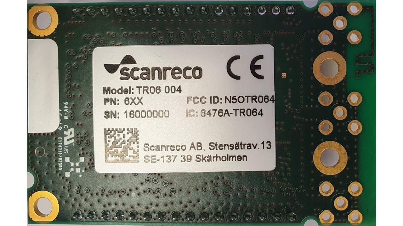
N5OTR064
Apr 25, 2021TR06 Transceiver Module
Equipment Class
DTS - Digital Transmission SystemN5OD3DRCJ
Apr 21, 20202.4 GHz Transceiver
Equipment Class
DSS - Part 15 Spread Spectrum TransmitterN5OD3DRCMP
Feb 03, 20202.4 GHz Transceiver
Equipment Class
DSS - Part 15 Spread Spectrum Transmitter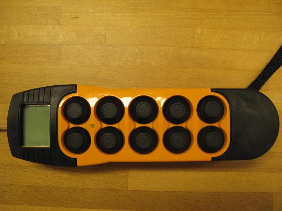
N5OD3DRC10
Aug 26, 20152.4 GHz Transceiver Model Number DRC-10 D3, DRC-10 2ST D3
Equipment Class
DSS - Part 15 Spread Spectrum Transmitter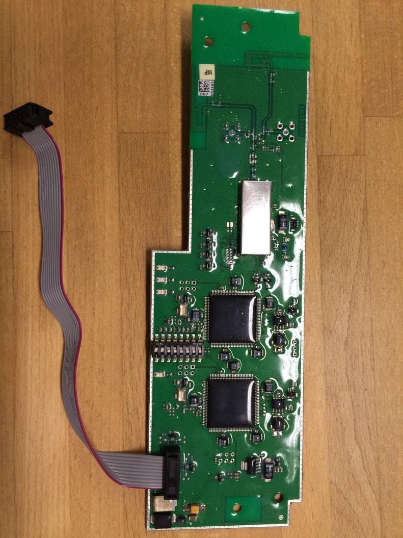
N5OD3DRCDRBM
Aug 25, 2015DRC-DR D3, DRC-BM D3
Equipment Class
DSS - Part 15 Spread Spectrum Transmitter