N5ORC917FHTR02Modular Transceiver
Scanreco AB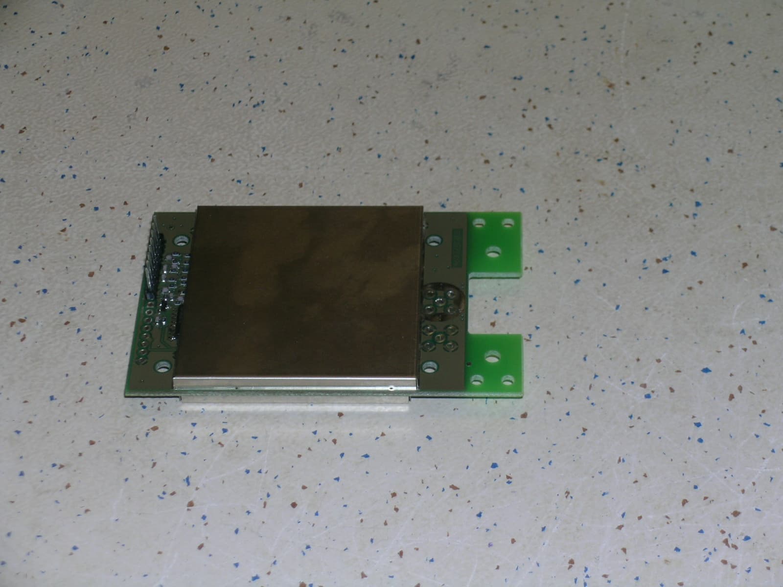
Click to zoom
Application Details
- Equipment Class
- DSS - Part 15 Spread Spectrum Transmitter
- Date of Grant
- Nov 06, 2006
- Application Purpose
- Original Equipment
- Date of Application
- Nov 06, 2006
- Equipment Note
- Modular Transceiver
- Frequency Range
- 915.00000000 - 919.90000000
- Company
- Scanreco AB
- Country
- Sweden
Documents & Files
Document Text
Text extracted from the exhibit documents filed with the FCC. Open a document above to read the original.
Cover Letter(s)
SCANRECO Industrielektronik AB Request for Confidentiality FCC ID: N5ORC917FHTR02 IC ID: 6476A-RC917FH/TR02 Product Name: RC917FH/TR02 To whom it may concern : Test-house, Telecommunication authority, Federal Communication Commission, Industry Canada, Equipment authorization division, Certification application etc. Pursuant to Sections 0.457 and 0.459 of the Federal Communication Commission rules, we hereby request that the following documents be held confidential: - Schematics - Block diagrams. - Operational description. - Users manual The application contains technical information which Scanreco AB, Sweden deems to be trade secrets and proprietary. If made public, the information might be used to the disadvantage of the applicant (Scanreco, Sweden) in the market place. This material is not customarily available to the general public and we request that it be withheld from public inspection. Thank you for your attention to this matter. Stockholm/Sweden / 2006-09-20 Kjell Leiwert Quality Manager Postal address Telephone +46 8 556 32 800 VAT nr SE556245004801 Box 47144 / Årsta Skolgränd 22 Telefax +46 8 556 32 828 Org. nr 556245 - 0048 S-100 74 STOCKHOLM / SWEDEN E-mail [email protected] Doc.nr : DokConf 1(1)
Cover Letter(s)
SCANRECO Industrielektronik AB Limited Modular Approval Request in accordance with DA 00-1407 Following characteristics applies to RC917FH-TR02 radio transceiver module designed and manufactured by Scanreco Industrielektronik AB 1. The module has its own shielding. One box on the front side and one on the back side. 2. All the inputs including data modulator input are buffered. 3. The module has it’s own power supply regulator. 4. The module is intended to work with two different antennas both of which are permanently attached. The internal antenna is soldered to the module. The other antenna which external, has its connection point inside the final product. The connection point of external antenna is not user accessible. 5. The module is fully tested in a stand-alone test fixture. The test fixture uses unmodified commercially available instrument to test the module. 6. The module is labeled with its own FCC ID number. Below is an example of label attached to the final product containing the module. Contains FCC ID: N5ORC917FHTR02 IC: 6476A-RC917FH/TR02 This device complies with part 15 of the FCC Rules. Operation is subject to the followingtwo conditions: (1) This device may not cause harmful interference, and (2) this device must accept any interference received, includin g interference that may cause undesired operation. Space for Importer 7. There are no specific rules for operating the module. The module is fully automatic. 8. The module comply with RF exposure requirements given in FCC Rules in Sections 2.1091, 2.1093 and 15.247 (b)(4). Kjell Leiwert Q uality Manager 2006-10-25 Postal address Telephone +46 8 556 32 800 VAT nr SE556245004801 Box 47144 / Årsta Skolgränd 22 Telefax +46 8 556 32 828 Org. nr 556245 - 0048 S-100 74 STOCKHOLM / SWEDEN E-mail [email protected] 1(1)
ID Label/Location Info
SCANRECO RC917 / TR 02 This device complies with part 15 of the FCC Rules. Operation is subject to following two conditions: (1) This device may not cause harmful interference, & (2) This device must accept any interference recelved, including interference that may cause indesired operation. FCC ID: N5ORC917FHTR02 IC: 6476A-RC917FH/TR02 SW:123456 BN:ABC123 PartNo:654321
RF Exposure Info
Ref: Nemko test report no: 72519R2b Espoo 24.10.2006 Equipment under test: Remote control: Transceiver RC917FH/TR02 Manufacturer: Scanreco Industrielektronik De Facto EIRP The EUT has two possible transmit antennas. The following data is from internal λ/2 dipole antenna. Maximum output power = 27.3 mW peak Transmission duration = 20.16 ms, this is 0.02016 s Number of hops in one hop cycle 50 Duration of hop cycle 1.1 s Antenna gain 2.66 numeric EIRP = 27.3 * (0.02016 * 50 / 1.1) * 2.66 = 66.5 mW This is below the general population low threshold for d > 2.5 cm of TCB exclusion list. This is 120/0.9199 = 130 mW. This filing is a limited modular approval for installation of this module by the manufacturer into their own products. The final application is industrial radio remote control products. The internal antenna will always be located at least 2.5 cm from the nearest host enclosure wall. Please refer to page 2 of the users manual. The following data is from External λ/4 antenna. Antenna gain 2 numeric Maximum output power = 27.3 mW peak EIRP = 27.3 * (0.02016 * 50 / 1.1) * 2 = 50.0 mW This is below the low threshold, however the external fixed antenna will be mounted at least 20 cm from nearby persons. For example; when used on fixed mount unit the antenna is often mounted somewhere high typically on the roof of a truck or lorry. Therefore this configuration will comply with RF exposure requirements.
Test Report
Nemko Oy • P.O.Box 19, FI-02601 Espoo, Finland Street address: Perkkaantie 11, FI-02600 Espoo Telephone +358 (0)424 5454 1 • Telefax +358 (0)9 5489 6371 T EST REPORT Date: ESPOO 24.10.2006 Page: 1 (13) Appendices − Date of handing in: 18.08.2006 Number: 72519R1b Tested by: No. 1 / 1 Reviewed by: SORT OF EQUIPMENT: Remote control MARKETING NAME: RC917FH/TR02 917 MHz Transceiver with single antenna TYPE: RC917FH/TR02 MANUFACTURER: Scanreco Industrielektronik CLIENT: Scanreco Industrielektronik ADDRESS: Årsta Skolgränd 22, S-100 74 Stockholm, SWEDEN TELEPHONE: +46 8 556 32 000 TEST LABORATORY: Nemko Oy FCC REG. NO. 91087 August 24, 2004 IC FILE NO. IC 4627-1 October 10, 2006 SUMMARY: In regard to the performed tests the equipment under test fulfils the requirements defined in the test specifications, see page 2 for details. This report supersedes test report no. 72519R1 dated 06.09.2006. The test results are valid for the tested unit only. Without a written permission of Nemko Oy it is allowed to copy this report as a whole, but not partially. Version f1.00 Type: RC917FH/TR02 FCC 47 CFR PART 15, SUBPART B, CLASS B Test report: 72519R1b Page 2 (13) Date 24.10.2006 Summary of performed tests and test results Emission tests according to the test specification FCC 47 CFR Part 15, Subpart B, Class B (2005) and ICES-003 Issue 4 (2004) Emission test Test method Conclusion Radiated disturbance 30-10000 MHz ANSI C63.4-2003 CISPR 22(1997) Pass, Class B Type: RC917FH/TR02 FCC 47 CFR PART 15, SUBPART B, CLASS B Test report: 72519R1b Page 3 (13) Date 24.10.2006 Contents Summary of performed tests and test results ..........................................................................................2 1. General................................................................................................................................................4 2. System Configuration..........................................................................................................................4 2.1 Test set-up ................................................................................................................................4 2.2 Operating conditions of the EUT...............................................................................................4 3. Test procedures ..................................................................................................................................5 3.1 Emission tests ...........................................................................................................................5 3.1.1 Radiated emissions...................................................................................................................5 4. Test results..........................................................................................................................................6 4.1 Emission tests ...........................................................................................................................6 4.1.1 Radiated emissions...................................................................................................................6 5. List of test equipment ........................................................................................................................10 6. Photographs ......................................................................................................................................11 Type: RC917FH/TR02 FCC 47 CFR PART 15, SUBPART B, CLASS B Test report: 72519R1b Page 4 (13) Date 24.10.2006 1. General The equipment under test (EUT) was a remote control. The purpose of the performed tests was to see if in regard to these tests the EUT fulfils the EMC requirements defined in the FCC 47 CFR PART 15, SUBPART B, CLASS B (2005). The tests were performed according to the test specifications CISPR 22 (1997) and ANSI C63.4 – 2003 and FCC 47 CFR PART 15, SUBPART B, CLASS B (2005) (radiated disturbances). The highest internal frequency of the EUT was 898.5 MHz. 2. System Configuration 2.1 Test set-up Equipment under test (EUT): • Remote control: Transceiver RC917FH/TR02, S/N:--- Cables: From To Type Length [m] Battery pack EUT DC cable, unshielded 0.2 Operating voltage of the EUT during the tests: • Rechargeable battery pack 7.2 VDC. 2.2 Operating conditions of the EUT Emission tests: For the duration of the tests the EUT was set to a receiving mode of operation. The device was powered off a fresh battery during the tests. 2.3 Channels of the EUT EUT Channel Frequency (MHz) Lowest 915.000 Highest 919.900 Type: RC917FH/TR02 FCC 47 CFR PART 15, SUBPART B, CLASS B Test report: 72519R1b Page 5 (13) Date 24.10.2006 3. Test procedures 3.1 Emission tests 3.1.1 Radiated emissions Site name Nemko / Perkkaa Date of testing 21-23.10.2006 Test equipment 350, 338, 566, 564, 544, 188, 542, 184 Test conditions 23 °C, 40 % RH Test result PASS The test was performed in a semi-anechoic shielded room. The EUT was placed on a non-conductive 0.8 m high table standing on the turntable (photographs 1 and 2). During the test in the frequency range 30-10000 MHz the distance from the EUT to the measuring antenna was 3 m. In order to find the maximum levels of the disturbance radiation the angle of the turntable, the height of the measuring antenna and the lay-out of the EUT cables were varied during the tests. The test was performed with the measuring antenna being both in horizontal and vertical polarizations. The measurements were performed the EUT at all three orthogonal planes. Vertical and horizontal polarizations in the frequency range 30 – 1000 MHz were measured by using the peak detector. During the peak detector scan the turntable was rotated from 0° to 360° with 30° step with the antenna heights 1.0 m and 3.0 m. The highest levels of the radiated interference field strength measured by using the quasi-peak detector were recorded. For measurements below 1 GHz the resolution bandwidth is s…
Text truncated - open the document above for the full version.
Test Report
Nemko Oy • P.O.Box 19, FI-02601 Espoo, Finland Street address: Perkkaantie 11, FI-02600 Espoo Telephone +358 (0)424 5454 1 • Telefax +358 (0)9 5489 6371 T EST REPORT Date: ESPOO 24.10.2006 Page: 1 (34) Appendices − Date of handing in: 18.08.2006 Number: 72519R2b Tested by: No. 1 / 1 Reviewed by: SORT OF EQUIPMENT: Remote control MARKETING NAME: RC917FH/TR02 917 MHz Transceiver with single antenna TYPE: RC917FH/TR02 MANUFACTURER: Scanreco Industrielektronik CLIENT: Scanreco Industrielektronik ADDRESS: Årsta Skolgränd 22, S-100 74 Stockholm, SWEDEN TELEPHONE: +46 8 556 32 000 TEST LABORATORY: Nemko Oy FCC REG. NO. 91087 August 24, 2004 IC FILE NO. IC 4627-1 October 10, 2006 SUMMARY: In regard to the performed tests the equipment under test fulfils the requirements defined in the test specifications, see page 2 for details. This report supersedes test report no. 72519R2 dated 06.09.2006. The test results are valid for the tested unit only. Without a written permission of Nemko Oy it is allowed to copy this report as a whole, but not partially. Version f1.00 Type: RC917FH/TR02 FCC 47 CFR PART 15, SUBPART C Test report: 72519R2b Page 2 (34) Date 24.10.2006 Summary of performed tests and test results Section in CFR 47 Section in RSS-210 Result 15.247, a1 A8.1 Carrier frequency separation PASS 15.247, a1i A8.1 Number of hopping frequencies PASS 15.247, a1i A8.1 Time of occupancy PASS 15.247, a1 A8.1 20 dB bandwidth PASS 15.247, b2 A8.4 (1) Peak output power PASS 15.247, d A8.5 Band-edge compliance of RF emissions PASS 15.247, d A8.5 Spurious RF conducted emissions PASS 15.247, d A8.5 Spurious radiated emissions PASS Explanations: PASS The EUT passed that particular test. FAIL The EUT failed that particular test. X The measurement was done, but there is no applicable performance criteria. Type: RC917FH/TR02 FCC 47 CFR PART 15, SUBPART C Test report: 72519R2b Page 3 (34) Date 24.10.2006 Contents Summary of performed tests and test results.......................................................................................... 2 1. General............................................................................................................................................... 4 2. System Configuration ......................................................................................................................... 4 2.1 Test set-up ............................................................................................................................... 4 2.2 Operating conditions of the EUT .............................................................................................. 4 2.3 Channels of the EUT................................................................................................................ 4 3. Test procedures ................................................................................................................................. 5 4. Test results ......................................................................................................................................... 6 4.1 Carrier frequency separation ...................................................................................................6 4.2 Number of hopping frequencies ............................................................................................... 7 4.3 Time of occupancy ................................................................................................................... 8 4.4 20 dB bandwidth .................................................................................................................... 10 4.5 Peak conducted output power ............................................................................................... 12 4.6 Band-edge compliance of RF conducted emissions.............................................................. 14 4.7 Spurious RF conducted emissions ........................................................................................ 18 4.8 Spurious radiated emission.................................................................................................... 21 5. List of test equipment ....................................................................................................................... 31 6. Photographs ..................................................................................................................................... 32 Type: RC917FH/TR02 FCC 47 CFR PART 15, SUBPART C Test report: 72519R2b Page 4 (34) Date 24.10.2006 1. General The equipment under test (EUT) was a remote control. The purpose of the performed tests was to see if in regard to these tests the EUT fulfils the requirements defined in the FCC 47 CFR PART 15, SUBPART C (2005). The tests were performed according to the test specifications CISPR 22 (1997), ANSI C63.4 – 2003, FCC 47 CFR PART 15, SUBPART C (2005) and RSS-210 (Issue 6, September 2005) 2. System Configuration 2.1 Test set-up Equipment under test (EUT): • Remote control: Transceiver RC917FH/TR02, S/N:--- Cables: From To Type Length [m] Battery pack EUT DC cable, unshielded 0.2 Operating voltage of the EUT during the tests: • Rechargeable battery pack 7.2 VDC. 2.2 Operating conditions of the EUT Emission tests: For the duration of the tests the EUT was set to a transmitting mode of operation. The device was powered off a fresh battery during the tests. 2.3 Channels of the EUT EUT Channel Frequency (MHz) Lowest 915.000 Highest 919.900 Type: RC917FH/TR02 FCC 47 CFR PART 15, SUBPART C Test report: 72519R2b Page 5 (34) Date 24.10.2006 3. Test procedures Radiated measurements The test was performed inside a semi anechoic shielded room. For the duration of the test the EUT was placed on a non-conductive support 0.8 m high standing on the turntable. The radiated power from the EUT was measured with an antenna fixed to an antenna tower. The tower and turn table were remotely controlled to turn the EUT and change the antenna polarization. T…
Text truncated - open the document above for the full version.
Test Report
SCANRECO Industrielektronik AB 1. Internal Dipole Antenna Fig 1: Dipole, E-plane, copol (horizontal pol) Postal address Telephone +46 8 556 32 800 VAT nr SE556245004801 Box 47144 / Årsta Skolgränd 22 Telefax +46 8 556 32 828 Org. nr 556245 - 0048 S-100 74 STOCKHOLM / SWEDEN E-mail [email protected] 1(4) SCANRECO Industrielektronik AB Fig 2: Dipole, E-plane, xpol (vertical pol) Fig 3: Dipole, H-plane, copol (vertical pol) Fig 4: Dipole, H-plane, xpol (horizontal pol) Postal address Telephone +46 8 556 32 800 VAT nr SE556245004801 Box 47144 / Årsta Skolgränd 22 Telefax +46 8 556 32 828 Org. nr 556245 - 0048 S-100 74 STOCKHOLM / SWEDEN E-mail [email protected] 2(4) SCANRECO Industrielektronik AB 2. External Monopole Antenna Fig 5: Monopole, E-plane, copol (horizontal pol) Fig 6: Monopole, E-plane, xpol (vertical pol) Postal address Telephone +46 8 556 32 800 VAT nr SE556245004801 Box 47144 / Årsta Skolgränd 22 Telefax +46 8 556 32 828 Org. nr 556245 - 0048 S-100 74 STOCKHOLM / SWEDEN E-mail [email protected] 3(4) SCANRECO Industrielektronik AB Fig 7: Monopole, H-plane, copol (vertical pol) Fig 8: Monopole, H-plane, xpol (horizontal pol) Postal address Telephone +46 8 556 32 800 VAT nr SE556245004801 Box 47144 / Årsta Skolgränd 22 Telefax +46 8 556 32 828 Org. nr 556245 - 0048 S-100 74 STOCKHOLM / SWEDEN E-mail [email protected] 4(4)
Test Setup Photos
Type: RC917FH/TR02 FCC 47 CFR PART 15, SUBPART C Test report: 72519R2b Page 32 (34) Date 24.10.2006 6. Photographs Photograph 1 Radiated emissions test setup Photograph 2 Radiated emissions test setup Type: RC917FH/TR02 FCC 47 CFR PART 15, SUBPART C Test report: 72519R2b Page 33 (34) Date 24.10.2006 Photograph 3 Radiated emissions test setup Photograph 4 Radiated emissions test setup Type: RC917FH/TR02 FCC 47 CFR PART 15, SUBPART C Test report: 72519R2b Page 34 (34) Date 24.10.2006 Photograph 5 Radiated emissions test setup Photograph 6 Radiated emissions test setup
Contact Information
Applicant
Bjorn Askestig(Vice President)
Technical Contact
Scanreco Industrielektronik ABRamin Fardi
[email protected]+46 8 556 32 800
P.O.BOX 47144 · Stockholm · Sweden
Non-Technical Contact
Scanreco Industrielektronik ABKjell Leiwert
[email protected]+46 8 556 32 800
Test Firm
Nemko Canada Inc. (Ottawa)Charles Neal
Technical Specifications
| # | Rule Parts | Frequency Range | Power Output |
|---|---|---|---|
| 1 | 15C | 915 MHz - 919.9 MHz | 27.00 mW |
Other Applications from Scanreco AB
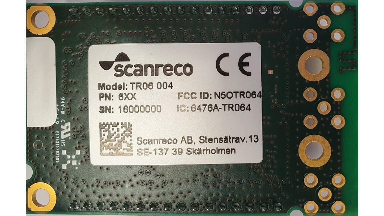
N5OTR064
Apr 25, 2021TR06 Transceiver Module
Equipment Class
DTS - Digital Transmission SystemN5OD3DRCJ
Apr 21, 20202.4 GHz Transceiver
Equipment Class
DSS - Part 15 Spread Spectrum TransmitterN5OD3DRCMP
Feb 03, 20202.4 GHz Transceiver
Equipment Class
DSS - Part 15 Spread Spectrum Transmitter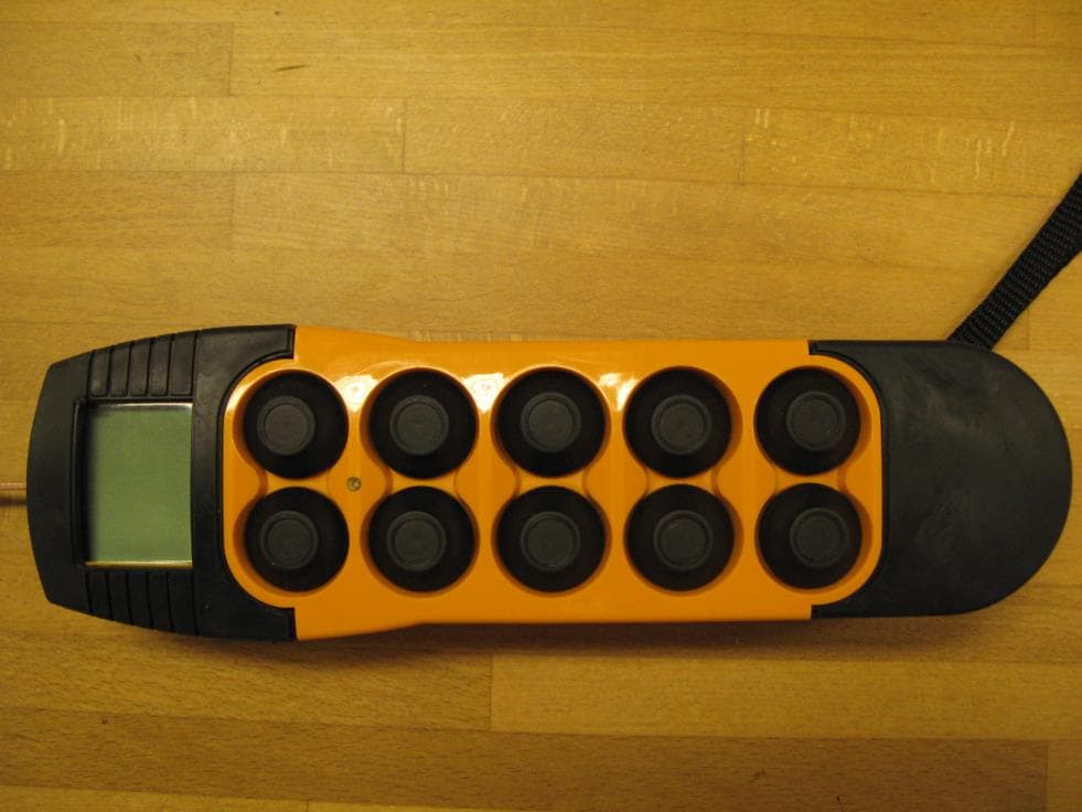
N5OD3DRC10
Aug 26, 20152.4 GHz Transceiver Model Number DRC-10 D3, DRC-10 2ST D3
Equipment Class
DSS - Part 15 Spread Spectrum Transmitter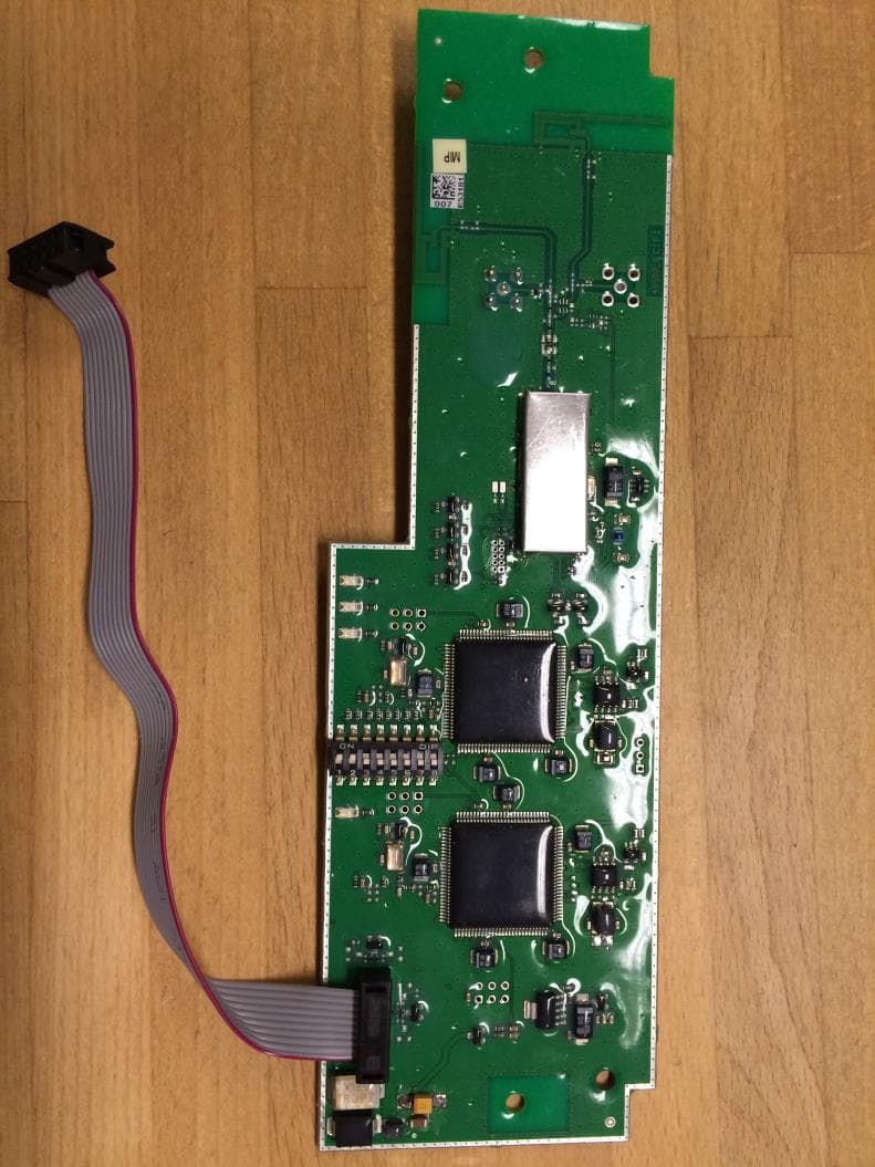
N5OD3DRCDRBM
Aug 25, 2015DRC-DR D3, DRC-BM D3
Equipment Class
DSS - Part 15 Spread Spectrum Transmitter