N6SGBIR15RFID Reader
Gilbarco Inc.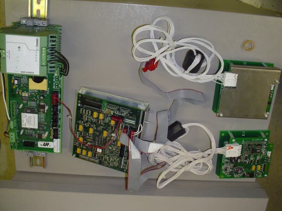
Click to zoom
Application Details
- Equipment Class
- DXX - Part 15 Low Power Communication Device Transmitter
- Date of Grant
- Feb 01, 2006
- Application Purpose
- Original Equipment
- Date of Application
- Jan 31, 2006
- Equipment Note
- RFID Reader
- Frequency Range
- 0.13420000 - 0.13420000
- Company
- Gilbarco Inc.
- Country
- United States
Documents & Files
Document Text
Text extracted from the exhibit documents filed with the FCC. Open a document above to read the original.
Users Manual
MDE-4544 Encore S Series TRIND Retrofit Kit C00011-011 Installation Manual • January 2006Page 1 Draft Introduction Purpose This manual provides instructions for installing the TRIND ® C00011-011 Retrofit Kit into Encore ® S Series ™ units that contain the CRIND ® device. The Transmitter/Receiver In Dispenser (TRIND) option allows customers to automatically authorize Card Reader In Dispenser (CRIND) device-equipped units using a hand-held low frequency transponder tags provided by a Major Oil Company (MOC) or retailer. Use this kit for one or two-sided unit. Important Notice This equipment has been tested and found to comply with the limits for a Class A digital device pursuant to Part 15 of the Federal Communications Commission (FCC) Rules. These limits are designed to provide reasonable protection against harmful interference when the equipment is operated in a commercial environment. This equipment generates, uses and can radiate radio frequency energy, and if not installed and used in accordance with the instruction manual, may cause harmful interference to radio communications. Operation of this equipment in a residential area may cause harmful interference in which case the user will be required to correct the interference at his own expense. Changes or modifications not expressly approved by the manufacturer could void the user’s authority to operate this equipment. The long term characteristics or the possible physiological effects of radio frequency electromagnetic fields have not yet been investigated by Underwriters’ Laboratories, Incorporated (UL ® ). Required Reading Before installing the equipment, the installer must read, understand, and follow: • this manual • National Fire Protection Agency (NFPA) 30A, The Automotive and Marine Service Station Code • NFPA 70, The National Electric Code • applicable federal, state and local codes and regulations Failure to do so may adversely effect the safe use and operation of the equipment. Note: This kit must be installed by a Gilbarco Authorized Service Contractor (ASC) MDE-4544 Encore S Series TRIND Retrofit Kit C00011-011 Installation Manual January 2006 Introduction Page 2MDE-4544 Encore S Series TRIND Retrofit Kit C00011-011 Installation Manual • January 2006 Draft Related Documents Document Number DescriptionGOLD Library MDE-3804Encore and Eclipse Series Start-Up/Service ManualEncore and Eclipse MDE-4516Encore S Series Owners ManualEncore and Eclipse MDE-3664TRIND Start-Up, Service, and Parts ManualCRIND and TRIND PT-1936Encore Illustrated Parts ManualParts Manual PT-1736CRIND Card Reader Illustrated Parts ManualParts Manual Recommended Tools The following equipment is needed to install TRIND kit M02112K00X: • clean cloth or rag • isopropyl alcohol (part number END-1082) • nut drivers, metric • nut drives, standard • multimeter • needle nose pliers • pliers • pocket knife • putty knife or scraper • Diagnostic Card Q12534-170 • ratchet set, metric • ratchet set, standard • screwdrivers, flat and Phillips head • static guard wrist strap • TRIND ASC tool kit K94577-02 (refer to MDE-3640 ASC TRIND Installation Tool Kit) MDE-4544 Encore S Series TRIND Retrofit Kit C00011-011 Installation Manual • January 2006Page 3 Parts Lists Draft Parts Lists TRIND Retrofit Kit C00011-011 Parts List The following section provide the parts lists for kit C00011-011. The kit is designed for a dual- sided unit. DescriptionPart NumberQuantity Assembly, TRIND ElectronicsM06380A0011 Assembly, Light and InductorM06143A00X(see note 1) Cable Group:Q13863-12 1 • TRIND Door Cable (Side 1)M00507A0011 • TRIND Door Cable (Side 2)M00507A0021 • Cable, TRIND Gateway to CCNM00515A0021 • Cable, TRIND Option Door Data and PowerR20773-G12 • Cable, TRIND Power Enhanced EncoreM06525A0011 Graphics (Envelope)T18832-011 Jumper, 0.100 CentersQ11011-0110 Kit, Encore S Parts:K96646-04- • Window, TRIND DisplayM05987B0011 Kit, TRIND Encore Component Parts:M02183K001- • Cable Mount, AdhesiveQ13558-0416 • Screw, Self-Tapping HexQ11677-236 •Tie, CableQ10178-014 Label, Patent and FCCM02962B0071 Notes: 1. Part M06143A00X is a customer specific order entry item (A001 is red, A002 is orange). 2. Part M06525A001 is a customer specific order entry item (based on site survey data). ASC TRIND Tool Kit K94577-02 The following section provide the lists the parts for ASC TRIND Tool Kit K94577-02. The ASC TRIND Tool kit is a separate order entry item and is not included with the retrofit kit. DescriptionPart NumberQuantity Tool Kit, ASC TRIND K94577-02- • cable, standalone jumperR20602-G21 • test tag, TI/RFID hand heldQ13630-021 Important Safety Information Page 4MDE-4544 Encore S Series TRIND Retrofit Kit C00011-011 Installation Manual • January 2006 Draft Important Safety Information This section introduces the hazards and safety precautions associated with installing, inspecting, maintaining or servicing this product. Before performing any task on this product, read this safety information and the applicable sections in this manual, where additional hazards and safety precautions for your task will be found. Fire, explosion, electrical shock or pressure release could occur and cause death or serious injury if these safe service procedures are not followed. Preliminary Precautions You are working in a potentially dangerous environment of flammable fuels, vapors, and high voltage or pressures. Only trained or authorized individuals knowledgeable in the related procedures should install, inspect, maintain or service this equipment. The first and most important information you must know is how to stop all fuel flow to the pump and island. Emergency Total Electrical Shut-Off Locate the switch or circuit breakers that shut-off all power to all fueling equipment, dispensing devices, and submerged turbine pumps (STPs). These you must operate in the event of an emergency. The EMERGENCY STOP, ALL STOP, and PUMP STOP buttons at the cashier’s station WILL NOT shut off electrical power to the pump/dispens…
Text truncated - open the document above for the full version.
Cover Letter(s)
Gilbarco Inc. 7300 W. Friendly Avenue P. O. Box 22087 Greensboro, NC 27420-2087 USA Telephone: 336 547 5000 Fax: 336 292 8871 Telex: 4949970 Web site: www.gilbarco.com Cover Letter Date January 5, 2006 American Telecommunications Certification Body, Inc. 6731 Whittier Avenue Suite C110 McLean, VA 22101 To Whom It May Concern: The purpose of this submission is to receive grants from the FCC (N6SGBIR15 – modular approval) and Industry Canada (827B-GBIR15) for the Encore S TRIND intentional radiator product. Confidentiality is requested for Gilbarco and Texas Instruments for electrical schematics. Thank you for your attention to this matter. Sincerely, Lester Ward (Manager of Reliability Engineering)
Cover Letter(s)
Gilbarco Inc. is requesting Modular Approval for FCC ID. N6SMRIR6. The following provides responses to the 8 questions that a specified in PART 15 UNLICENSED MODULAR TRANSMITTER APPROVAL (DA 00-1407 Released: June 26, 2000). PART 15 UNLICENSED MODULAR TRANSMITTER APPROVAL In order to obtain a modular transmitter approval, a cover letter requesting modular approval must be submitted and the numbered requirements identified below must be addressed in the application for equipment authorization. 1. The modular transmitter must have its own RF shielding. This is intended to ensure that the module does not have to rely upon the shielding provided by the device into which it is installed in order for all modular transmitter emissions to comply with Part 15 limits. It is also intended to prevent coupling between the RF circuitry of the module and any wires or circuits in the device into which the module is installed. Such coupling may result in non- compliant operation. The Light/MicroReader/Antenna assembly, p/n M06143A00x) includes a formed sheet metal shield, p/n M06567B001, which was designed to provide mechanical and electrical protection for the assembly when mounted in a typical installation configuration. 2. The modular transmitter must have buffered modulation/data inputs (if such inputs are provided) to ensure that the module will comply with Part 15 requirements under conditions of excessive data rates or over-modulation. The modular transmitter has three data lines (two internal and one external) in the system. Two RS-232 internal lines connect the Enhanced Gateway PCA (Gilbarco p/n T20678 G1) to each M06143A00x Light/MicroReader/Antenna assembly. These lines pass transponder serial numbers and on/off commands for the recognition light. There are no commands from the Enhanced Gateway PCA that can change performance and RFID functionality of the Texas Instruments MicroReader on the M06143A00x assembly. One TTL line connects the Enhanced Gateway PCA to the fuel dispenser. It passes transponder serial number and authentication code to the dispenser electronics for communication to the point-of-sale (POS) system for credit verification. Once the credit is verified, the POS system instructs the transmitter module to keep the recognition light on or to shut it off. 2 3. The modular transmitter must have its own power supply regulation. This is intended to ensure that the module will comply with Part 15 requirements regardless of the design of the power supplying circuitry in the device into which the module is installed. The M06143A00x assembly includes a switching power supply as part of the M06100A001 PCA. This power supply down converts the +24VDC supplied by the dispenser electronics to the +5VDC required by all components of the modular transmitter system. (The +24VDC from the dispenser is actually passed through the Enhanced Gateway PCA to the M06143A00x assembly where the regulation occurs. The regulated +5VDC is then available to feed the MicroReader and associated circuitry of the intentional radiator on the M06100A001 PCA, as well as being fed back to the Enhanced Gateway PCA, T20678 G1, to drive the logic circuits there.) 4. The modular transmitter must comply with the antenna requirements of Section 15.203 and 15.204(c). The antenna must either be permanently attached or employ a “unique” antenna coupler (at all connections between the module and the antenna, including the cable). Any antenna used with the module must be approved with the module, either at the time of initial authorization or through a Class II permissive change. The “professional installation” provision of Section 15.203 may not be applied to modules. This device employs a unique coupler configuration that depends on the mechanical fastener hardware to also make the electrical connection between the Antenna PCA, p/n M06074A001, and the circuitry of the intentional radiator electronic on the Light/MicroReader PCA M06100A001. This physical and electrical connection is permanent; the system is rendered inoperable if any modification of the physical connection is attempted. 5. The modular transmitter must be tested in a stand-alone configuration, i.e., the module must not be inside another device during testing. This is intended to demonstrate that the module is capable of complying with Part 15 emission limits regardless of the device into which it is eventually installed. Unless the transmitter module will be battery powered, it must comply with the AC line conducted requirements found in Section 15.207. AC or DC power lines and data input/output lines connected to the module must not contain ferrites, unless they will be marketed with the module (see Section 15.27(a)). The length of these lines shall be length typical of actual use or, if that length is unknown, at least 10 centimeters to insure that there is no coupling between the case of the module and supporting equipment. Any accessories, peripherals, or support equipment connected to the module during testing shall be unmodified or commercially available (see Section 15.31(i)). As the photographs and report indicates, the device was tested in a stand-alone configuration and not inside another device. It does not contain any ferrites that will not be marketed with the module. The device was tested with cables of a length typical of actual use that are greater than 10 centimeters long. There were no accessories, peripherals, or support equipment connected to the module. The module interfaces with a fuel dispenser, which is the device into which the module is installed in its final application. 3 6. The modular transmitter must be labeled with its own FCC ID number, and, if the FCC ID is not visible when the module is installed inside another device, then the outside of the device into which the module is installed must also display a label referring to the enclosed module. This exterior label can use wording such as the following: “Contains Transmitter Mod…
Text truncated - open the document above for the full version.
Cover Letter(s)
Gilbarco Inc. 7300 W. Friendly Avenue P. O. Box 22087 Greensboro, NC 27420-2087 USA Telephone: 336 547 5000 Fax: 336 292 8871 Telex: 4949970 Web site: www.gilbarco.com Letter Of Agency Date 10/21/2005 American Telecommunications Certification Body, Inc. 6731 Whittier Avenue Suite C110 McLean, VA 22101 To Whom It May Concern: Please be advised that Gilbarco authorizes American Telecommunications Certification Body, Inc.to act on our behalf, until otherwise notified, for applications submitted to American Telecommunications Certification Body, Inc. (ATCB). Gilbarco Inc.’s FRN number is 0003-7489-28. We certify that we are not subject to denial of federal benefits, that includes FCC benefits, pursuant to Section 5301 of the Anti-Drug Abuse ACT of 1988, U.S.C. 862. Further, no party, as defined in 47 CFR 1.2002(b), to the application is subject to denial of federal benefits, that includes FCC benefits. Thank you for your attention to this matter. Specifically N6SGBIR15 (Encore S series TRIND) Sincerely, Lester Ward (Manager of Reliability Engineering)
Cover Letter(s)
Gilbarco Inc. 7300 W. Friendly Avenue P. O. Box 22087 Greensboro, NC 27420-2087 USA Telephone: 336 547 5000 Fax: 336 292 8871 Telex: 4949970 Web site: www.gilbarco.com Request for Confidentiality Date 1/4/2006 American Telecommunications Certification Body, Inc. 6731 Whittier Avenue Suite C110 McLean, VA 22101 RE: Certification Application FCC ID: N6SGBIR15 IC ID: 827B-GBIR15 To Whom It May Concern: In reference to FCC ID N6SGBIR15/IC ID 827B-GBIR15, Gilbarco is requesting confidentiality for schematic diagrams. Gilbarco posted file: Encore S series TRIND EMC Components and Electrical Schematics.pdf Texas Instruments posted files on behalf of Gilbarco as follows: • Electrical schematics MicroReader RI-STU-MRD1-01 *** When their confidential files are posted Texas Instruments may submit a more detailed letter of confidentiality for the documents that they wish to have kept confidential *** This request is being made under the provisions of Section 0.457(d) of the Commission’s rules, and Section 552(b)(4) of the Freedom of Information Act. These schematic diagrams are proprietary and not customarily released to the public. As a matter of fact, those schematics involving the Texas Instruments components were posted directly by TI (even Gilbarco is not privileged to view them). These schematic diagrams should fall within the scope of Section 552(b)(4) as trade secrets, Under the provisions of Section 0.457(d), these schematic diagrams should not be routinely available for public inspection. The application contains technical information, which Gilbarco deems to be trade secrets and proprietary. If made public, the information might be used to the disadvantage of the applicant in the market place. Thank you for your attention to this matter. Sincerely, Lester Ward (Manager of Reliability Engineering)
Cover Letter(s)
Gilbarco Inc. 7300 W. Friendly Avenue P. O. Box 22087 Greensboro, NC 27420-2087 USA Telephone: 336 547 5000 Fax: 336 292 8871 Telex: 4949970 Web site: www.gilbarco.com Manufacturer’s Letter Date 10/21/2005 American Telecommunications Certification Body, Inc. 6731 Whittier Avenue Suite C110 McLean, VA 22101 RE: Certification Application FCC ID: N6SGBIR15 To Whom It May Concern: Please be advised that the manufacturer will ensure that the above-referenced model will be manufactured in accordance with the FCC Rules and Regulations. Thank you for your attention to this matter. Sincerely, Lester Ward (Manager of Reliability Engineering)
External Photos
FCC ID: N67SGBIR15 EXTERNAL PHOTOS OF TESTED EUT FCC ID: N67SGBIR15 General View - Power Supply, Gateway, and Antenna/Light/Micro-reader Assy FCC ID: N67SGBIR15 General View - Enhanced Gateway PCA T20678 FCC ID: N67SGBIR15 General View - Light/Micro-reader PCA M06100, top view FCC ID: N67SGBIR15 General View - Light/Micro-reader PCA M06100, bottom view FCC ID: N67SGBIR15 General View - Bezel Antenna PCA M06074, top view FCC ID: N67SGBIR15 General View - Bezel Antenna PCA M06074, bottom view
ID Label/Location Info
N6SGBIR15 FCC and IC Labels FCC and IC label locations on Encore S series fuel dispenser for N6SGBIR15 TRIND Page 1 of 4 Label 3 is attached to the Gateway board T20678-G1bracket (galvanized metal). The M06143 Assembly actually has the intentional radiator, but the board is to small to hold the label. Sticking the label to the Polycarbonate bezel is not an option since the label would probably fall off. Label 1: FCC and Patent Label combination Units are millimeters. Location: exterior to dispenser on inner dispenser column sheathing. Page 2 of 4 ICIC IC
Internal Photos
FCC ID: N67SGBIR15 INTERNAL PHOTOS OF TESTED EUT FCC ID: N67SGBIR15 General View - Power Supply, Gateway, and Antenna/Light/ Micro-Reader Assembly. Note power supply cables (M01366A001) from the Gateway board to the Mirco-reader board have a ferrite (Q11433 108). FCC ID: N67SGBIR15 General View - Enhanced Gateway PCA T20678 The Gateway board is an interface between the M06143 Light Inductor Assembly (which contains the M06100 TRIND Light PCA which in turn contains the RI-STU-MRD1-01 which is the actual Intentional radiator) and the Dispenser (Pump head/ point of sale) FCC ID: N67SGBIR15 Front View - Enhanced Gateway PCA T20678 Acts as an interface between the RFID board and Dispenser (POS) FCC ID: N67SGBIR15 Enhanced Gateway PCA T20678, back view Acts as an interface between the RFID board and Dispenser (POS) Back of M06100 TRIND LIGHT PCA showing the light FCC ID: N67SGBIR15 General View - Bezel Antenna PCA M06074, top view FCC ID: N67SGBIR15 General View - Bezel Antenna PCA M06074, bottom view FCC ID: N67SGBIR15 Cropped close up View - TI Micro-reader TI # RI-STU-MRD1-01/Gilbarco # Q13551-01
Internal Photos
Front - M06100 TRIND Light PCA. It contains the intentional radiator board (RI-STU-MRD1-01)
Operational Description
1.0 General Information FCC ID: N6SGBIR15 And IC: 827B-GBIR15 Product Description Gilbarco Inc.'s product (for which this submittal is being filed) allows customers wishing to purchase motor fuel or other products to interface directly with a fuel dispenser or other point-of- sale device via a handheld transponder. The product is called TRIND ™ (TRIND: Transmitter/Receiver In Dispenser). The TRIND™ transmits at 134.2kHz, which provides energy to the handheld tag. The handheld tags contain a unique and secure ID code so each customer can be identified by their individually registered tag. The low frequency antennas of the system create magnetic charge-up fields known as "read-zones." As soon as a tag enters the "read-zone," the reader receives the unique ID code. The TRIND™ is a Radio Frequency Identification Device (RFID) which is designed for use in conjunction with passive transponders (not requiring a battery), Texas Instruments Part # RI-TRP- Series. The user/customer carries the handheld transponder. The transmitter portion of the TRIND™ operates at 134.2kHz and is subject to FCC Part 15, Subpart C, "Intentional Radiator;” paragraphs 15.207 and 15.209. The digital electronics portion of the TRIND™ is subject to FCC Part 15, Subpart B, "Unintentional Radiator", paragraph 15.109, under the Class A limits and as such, the TRIND™ is incorporated into an application that is subject to Class A limits. Tested System Details The TRIND™ System is typically mounted into an enclosure such as a fueling dispenser and, in the case of an Encore S Series dispenser, the system includes one Enhanced Gateway PCA (T20678), two 134.2kHz low 'Q' printed circuit board antennas (M06074), two Light/Micro- Reader Boards (M06100) (M06074 and M06100 are both part of the assembly p/n M06143), and one switched DC Power Supply (M04104). These components are listed in Table 1.1, and the functional relationship is provided in Figure 1: TRIND™ RFID Functional Block Diagram. The 134.2 kHz transmit signal originates on the MicroReader located on the Light/MicroReader Board and travels via their respective cables to their respective antennas where it is intentionally radiated. In the case of M06143, there is no connector between the intentional radiator and the antenna as that assembly relies on the conductivity of the metal PC board stand-offs to electrically connect the antenna PCA to the Light/MicroReader PCA. These components are assembled per the drawings in the EMC Components and Electrical Schematics document, also included with this submission. The TRIND™ operates on 120VAC converted to 24VAC. The 24VAC is then rectified and converted to +22.5VDC and +5VDC by means of a switching power supply that is integral to the M06100 PCA. The system functional block diagram is located in the EMC Components and Electrical Schematics document, also included in this submission. Circuit Board Descriptions • The Power Supply Assembly (M04104) provides switched +24VDC to the Enhanced Gateway PCA (T20678) where it is passed through to the Light/MicroReader PCA (M06100). • The Light/MicroReader PCA converts the +24VDC to +22VDC, +5VDC and GND to feed the MicroReader from Texas Instruments (part of the M06100 PCA) and to also feed back to and power the Enhanced Gateway PCA (via loop-back circuitry on the M06100 PCA). The Enhanced Gateway PCA uses +5VDC and GND created on the M06100 PCA (from the same connector that feeds the M06100) to operate its digital logic circuitry. • The RFID Light/MicroReader PCA (M06100) has digital interface and RS-232 conversion circuitry, an eight-bit micro-controller (Philips 87C750) with an embedded program to interact with the MicroReader that is soldered on. It also has a current-limited light-emitting diode (LED) circuit that functions as an indicator to the customer confirming that hand-held transponder has been read and is in use. • The MicroReader, (Texas Instruments part number RI-STU-MRD1 or RI-STU-MRD1-01), is soldered onto the Light/MicroReader PCA. It has a serial communications interface (SCI), which supports RS-232 protocol communication and TTL data communication. It provides radio frequency (RF) 134 kHz control functions to read appropriate Texas Instruments transponders and works together with a 47μH, low 'Q' antenna. This equipment configuration does not require tuning. • The M06074 Antenna PCA is a 47μH, low 'Q' (10-20) antenna that works with the MicroReader. The M06074 Antenna PCA is electrically connected to the Light/MicroReader PCA via two of the three metal PC board stand-offs. This mechanical hardware functions in place of connectors and/or cabling and is insulated with heat shrink tubing, per details found on the M06143 assembly drawing, also included with this submittal. The M06074 Antenna PCA is energized by the MicroReader (on the Light/MicroReader PCA) at 132kHz to generate the exciter frequency of 134.2kHz. Because of its’ low 'Q', it does not need to be tuned any further in this application. • The Antenna/Light/MicroReader Assembly (M06143) is simply an assembly of the M06100 Light/MicroReader PCA and the M06074 Antenna PCA. This assembly also includes a metal shield and associated fastening hardware that protects and shields the rear of the assembly as typically mounted in a gasoline dispenser. • The TRIND™ Enhanced Gateway PCA (T20678) manages RFID processing and provides simple, generic event messages to the gasoline dispenser electronics via TTL (transistor- transistor-logic). Table 1. 1 TESTED LF SYSTEM COMPONENTS Component Description Gilbarco Part Number Texas Instruments Part Number Power Supply (1) M04104 NA Light/Micro-Reader PCA (2) M06100 NA MicroReader (2) (one per M06100) (one per MO6143) Q13551-01 RI-STU-MRD1 or RI-STU-MRD1-01 134.2kHz Bezel Antenna PCA (2) M06074 NA Antenna(134.2kHz)/Light/ MicroReader Assembly (2) MO6143 NA TRIND™ Enhanced Gateway PCA (1) T20678 NA
Parts List/Tune Up Info
TRIND in Encore S Series - Bill of Material Bill of Material Explosion for PGM00024A009 (1 required per dispenser) Exploded 1 Level(s) Deep BOM ExplosionPart NumberDescriptionQuantityUOMLevelMfg SeqMfg Type Mfg Plant StatusIn-Effect Out- Effect Prod Class M06380A001 M06380A001ASSY, TRIND ELECT1EA1001000PurchasedGSOActive1/31/2006/ /1837 M00414B005 M00414B005NUT, METRIC, FLANGE3EA1002000PurchasedGSOActive1/31/2006/ /1837 M06525A001 M06525A001CABLE, TRIND POWER1EA1003000PurchasedGSOActive1/31/2006/ /1837 M02962B007 M02962B007DECAL, PATENT AND FCC1EA1004000PurchasedGSOActive1/31/2006/ /NS01 R20775 R20775DIAGRAM, BLOCK0NA1005000PurchasedGSOActive1/31/2006/ /1801 T20663 T20663DIAGRAM, INTERCONNECTION0NA1006000PurchasedGSOActive1/31/2006/ /NS01 Q11011 01 Q11011 01CONNT JUMPER .100 CTR10EA1007000PurchasedGSOActive1/31/2006/ /1896 M00515A002 M00515A002CABLE, TRIND GATEWAY TO CRIND1EA1008000PurchasedGSOActive1/31/2006/ /1896 M00507A001 M00507A001CABLE, TRIND DOOR (SIDE 1)1EA1009000PurchasedGSOActive1/31/2006/ /1896 M00507A002 M00507A002CABLE, TRIND DOOR (SIDE 2)1EA1001000PurchasedGSOActive1/31/2006/ /1896 R20773 G1 R20773 G1CABLE, TRIND DOOR DATA & PWR2EA1001100PurchasedGSOActive1/31/2006/ /1896 Bill of Material Explosion for PGM00435A003 (2 required per dispenser) Exploded 2 Level(s) Deep BOM ExplosionPart NumberDescriptionQuantityUOMLevelMfg SeqMfg Type Mfg Plant StatusIn-Effect Out- Effect Prod Class M06143A001 M06143A001ASSY, LIGHT & INDUCTOR1EA1001000PurchasedGSOActive5/24/2005/ /1837 | |--Q10651 04 Q10651 04SUPRT CKT BD LOCKING2EA2001000PurchasedGSOActive1/31/2006/ /1808 | |--Q10651 12 Q10651 12SUPRT CKT BD .50 LG1EA2002000PurchasedGSOActive1/31/2006/ /1808 | |--M06074A001 M06074A001PCA, RFID ANTENNA1EA2003000PurchasedGSOActive1/31/2006/ /3302 | |--M06100A001 M06100A001PCA, RFID MICRO READER1EA2004000PurchasedGSOActive1/31/2006/ /3302 | |--Q12083 13 Q12083 13SCREW SEMS PH PHIL 6-32X36EA2005000PurchasedGSOActive1/31/2006/ /1896 | |--M06567B001 M06567B001SHIELD, E2 TRIND PCB1EA2006000PurchasedGSOActive1/31/2006/ /1837 | |--Q10340 34 Q10340 34SPACR HEX THD 6-32X1.1253EA2007000PurchasedGSOActive1/31/2006/ /1801 | |--Q10141 07 Q10141 07TUBE HEAT SHRNK2FT2008000PurchasedGSOActive1/31/2006/ /1808 M05987B001 M05987B001LENS, TRIND1EA1002000PurchasedGSOActive5/24/2005/ /1837 M00419B117 M00419B117SCREW METRIC M4 X 84EA1003000PurchasedGSOActive5/24/2005/ /1896 Q11677 24 Q11677 24SCREW SEL TP HEX HD 6-20X3EA1004000PurchasedGSOActive10/24/2005/ /1801
Test Report
Project: 05CA45119 Underwriters Laboratories, Inc. Issued: 10/17/05 File: MC15028 Test Report on Electromagnetic Compatibility Page 17 of 32 FCC ID: N6SGBIR15 Test Report: 050110 IC: 827B-GBIR15 Test 3 - Results: Conducted Disturbance Emissions - Voltage Test Results Summary: Test Item Test Location Humidity (%) Temperature (ºC) Pass/Fail (P/F) Date Completed Comment # A A 53 23 P 10/14/05 The EUT was considered to Pass the Requirements. Comments: Comment # Description Test Equipment Used: Equipment ID Description Manufacturer Model Number Last Cal. Next Cal. ATA027 LISN, 150 kHz to 30 MHz Solar Electronics 9629-50-TS-25 4/21/05 4/30/06 ATA028 LISN, 150 kHz to 30 MHz Solar Electronics 9629-50-TS-25 4/21/05 4/30/06 ATA030 25 ft Cable, N - N UL RG-223 7/14/05 7/31/06 ATA056 Transient Limiter, 0.009 to 100 MHz Electro-Metrics EM-7600 3/11/05 3/31/06 ATA096 50 ft, N male - N male Micro-Coax Coaxial Cable 8/31/05 2/28/06 ATA143 Cable, 6ft., N-male to N-male Micro-Coax N/A 8/10/05 2/28/06 SAR003 EMC Receiver Rohde & Schwarz 1088.7490K40 12/02/04 12/31/05 The above equipment has been calibrated and is within the manufacturer’s published limit of error. Calibration is traceable to the National Institute of Standards & Technology(NIST) and conforms to ISO 17025:2005. Project: 05CA45119 Underwriters Laboratories, Inc. Issued: 10/17/05 File: MC15028 Test Report on Electromagnetic Compatibility Page 18 of 32 FCC ID: N6SGBIR15 Test Report: 050110 IC: 827B-GBIR15 Test 3, Item A – Peak Plot (Line): Conducted Disturbance Emissions - Voltage Note: Both AC Conducted General Limits and Class A Unintentional Limits are displayed. Emissions observed below 3 MHz are sourced from the power supply switching circuit (approximately 42 kHz) and are regarded as unintentional emissions, therefore Class A unintentional limit is applied. Project: 05CA45119 Underwriters Laboratories, Inc. Issued: 10/17/05 File: MC15028 Test Report on Electromagnetic Compatibility Page 19 of 32 FCC ID: N6SGBIR15 Test Report: 050110 IC: 827B-GBIR15 Test 3, Item A – Peak Plot (Neutral): Conducted Disturbance Emissions - Voltage Note: Both AC Conducted General Limits and Class A Unintentional Limits are displayed. Emissions observed below 3 MHz are sourced from the power supply switching circuit (approximately 42 kHz) and are regarded as unintentional emissions, therefore Class A unintentional limit is applied. Project: 05CA45119 Underwriters Laboratories, Inc. Issued: 10/17/05 File: MC15028 Test Report on Electromagnetic Compatibility Page 20 of 32 FCC ID: N6SGBIR15 Test Report: 050110 IC: 827B-GBIR15 Test 3, Item A – Frequency Table: Conducted Disturbance Emissions – Voltage Test Item (A-Z) Detector Type* (P/Q/A) Measured Conductor (Name) Measured Frequency (MHz) Measured Value (dBuV) Equip Correction (dB) Corrected Value (dBuV) Quasi-Peak Limit (dBuV) Spec Margin (dB) Average Limit (dBuV) Spec Margin (dB) See Comment (#)** A P Line 0.1721 44.4 10.6 55.0 79.0 -24.0 66.0 -11.0 1 A P Line 0.2155 39.7 10.6 50.3 79.0 -28.7 60.0 -9.7 1, 2 A P Line 0.2589 33.3 10.6 43.9 79.0 -35.1 60.0 -16.1 1 A P Line 2.3248 29.1 10.9 40…
Text truncated - open the document above for the full version.
Contact Information
Applicant
Bob Sykes(EMC Engineer)
Technical Contact
Gilbarco, Inc.Lester Ward
[email protected]336-547-5559
7300 West Friendly Ave. · Greensboro, North Carolina · United States
Test Firm
UL LLCRick Titus
Technical Specifications
| # | Rule Parts | Frequency Range | Power Output |
|---|---|---|---|
| 1 | 15C | 0.1342 MHz - 0.1342 MHz | - |
Other Applications from Gilbarco Inc.
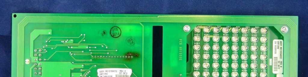
N6SLFSQR
Jun 23, 2015TRIND M01560 Module
Equipment Class
DCD - Part 15 Low Power Transmitter Below 1705 kHz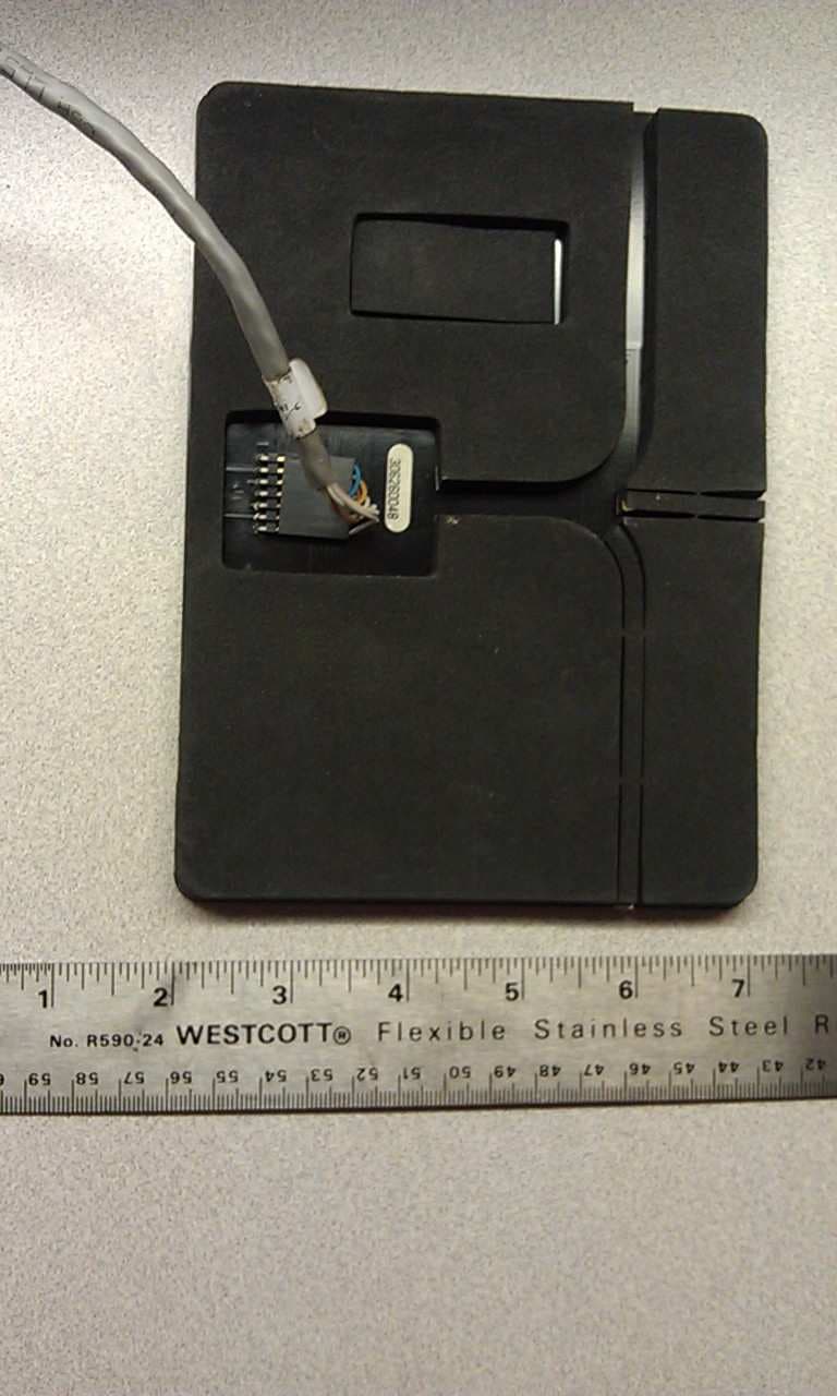
N6SLFMAT
Aug 12, 2013Mat Reader
Equipment Class
DCD - Part 15 Low Power Transmitter Below 1705 kHz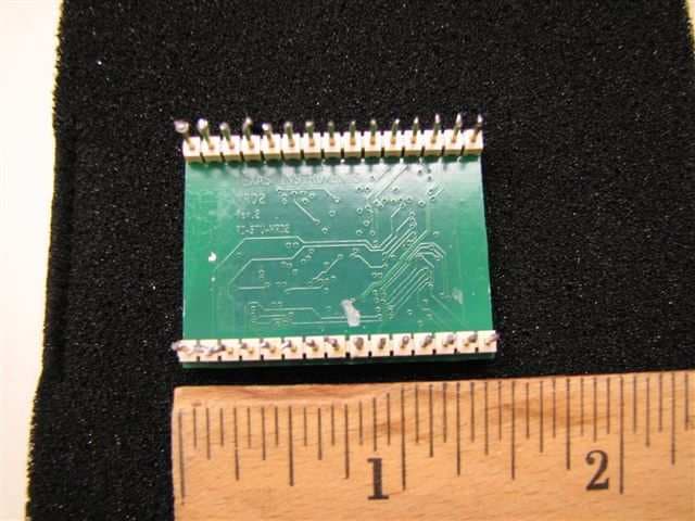
N6SLFECIM
Mar 26, 2013RFID Module
Equipment Class
DCD - Part 15 Low Power Transmitter Below 1705 kHz
N6SGCM
May 24, 2011Contactless Smart Card Interface
Equipment Class
DXX - Part 15 Low Power Communication Device Transmitter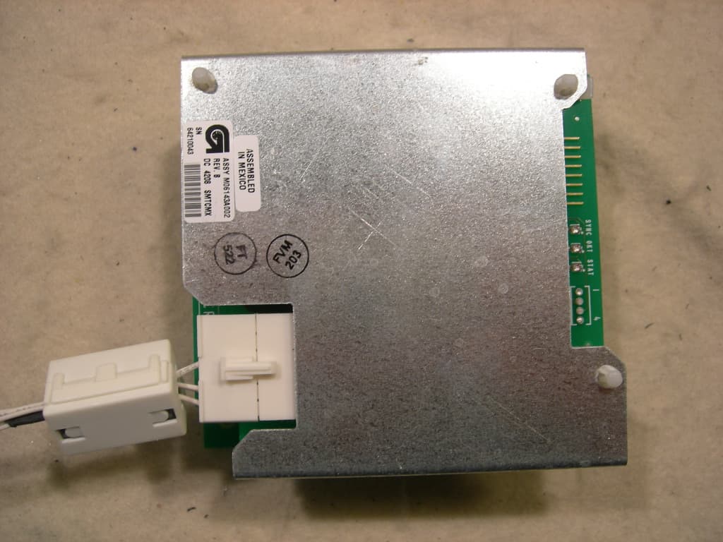
N6SLFTRIND
Jun 10, 2010TRIND RFID Module
Equipment Class
DCD - Part 15 Low Power Transmitter Below 1705 kHz