N6SLFSQRTRIND M01560 Module
Gilbarco Inc.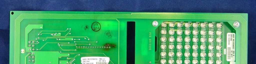
Click to zoom
Application Details
- Equipment Class
- DCD - Part 15 Low Power Transmitter Below 1705 kHz
- Date of Grant
- Jun 23, 2015
- Application Purpose
- Original Equipment
- Date of Application
- Jun 23, 2015
- Equipment Note
- TRIND M01560 Module
- Frequency Range
- 0.13420000 - 0.13420000
- Company
- Gilbarco Inc.
- Country
- United States
Documents & Files
Document Text
Text extracted from the exhibit documents filed with the FCC. Open a document above to read the original.
Users Manual
5015 B.U. Bowman Drive Buford, GA 30518 USA Voice: 770-831-8048 Fax: 770-831-8598 Certification Exhibit FCC ID: N6SLFSQR IC: 827B-LFSQR FCC Rule Part: 15.209 IC Radio Standards Specification: RSS-210 ACS Project Number: 13-0072 Manufacturer: Gilbarco, Inc. Model: LFSQR The Advantage ® Series, MPD ® -3, Encore ® , and Eclipse ® Units TRIND ® Start-up, Service, and Parts Manual MDE-3664B Computer Programs and Documentation All Gilbarco Inc. and/or Veeder Root Company computer programs (including software on diskettes and within memory chips) and documentation are copyrighted by, and shall remain the property of, Gilbarco Inc. and/or Veeder Root Company. Such computer programs and documents may also contain trade secret information. The duplication, disclosure, modification, or unauthorized use of computer programs or documentation is strictly prohibited, unless otherwise licensed by Gilbarco Inc. and/or Veeder Root Company. Federal Communications Commission (FCC) Warning This equipment has been tested and found to comply with the limits for a Class A digital device pursuant to Part 15 of the FCC Rules. These limits are designed to provide reasonable protection against harmful interference when the equipment is operated in a commercial environment. This equipment generates, uses, and can radiate radio frequency energy, and if not installed and used in accordance with the instruction manual, may cause harmful interference to radio communications. Operation of this equipment in a residential area is likely to cause harmful interference in which case the user will be required to correct the interference at his own expense. Changes or modifications not expressly approved by the manufacturer could void the user’s authority to operate this equipment. Industry Canada Warning This device complies with Industry Canada licence-exempt RSS standard(s). Operation is subject to the following two conditions: • this device may not cause interference, and • this device must accept any interference, including interference that may cause undesired operation of the device. Le présent appareil est conforme aux CNR d’Industrie Canada applicables aux appareils radio exempts de licence. L’exploitation est autorisée aux deux conditions suivantes : • l’appareil ne doit pas produire de brouillage, et • l’utilisateur de l’appareil doit accepter tout brouillage radioélectrique subi, même si le brouillage est susceptible d’en compromettre le fonctionnement. Under Industry Canada regulations, this radio transmitter may only operate using an antenna of a type and maximum (or lesser) gain approved for the transmitter by Industry Canada. To reduce potential radio interference to other users, the antenna type and its gain should be so chosen that the equivalent isotropically radiated power (e.i.r.p.) is not more than that necessary for successful communication. Conformément à la réglementation d’Industrie Canada, le présent émetteur radio peut fonctionner avec une antenne d’un type et d’un gain maximal (ou inférieur) approuvé pour l’émetteur par Industrie Canada. Dans le but de réduire les risques de brouillage radioélectrique à l’intention des autres utilisateurs, il faut choisir le type d’antenne et son gain de sorte que la puissance isotrope rayonnée équivalente (p.i.r.e.) ne dépasse pas l’intensité nécessaire à l’établissement d'une communication satisfaisante. Approvals Trademarks Gilbarco is an ISO 9001:2008 registered company. Underwriters Laboratories (UL): U L File#Products listed with U L MH1941 All Gilbarco pumps and dispensers that bear the UL listing mark. MH8467Transac System 1000 and PAM 1000 E105106Dell DHM Minitower E165027G-SITE and Passport Systems National Conference of Weights and Measures (NCWM) - Certificate of Conformance (CoC): Gilbarco pumps and dispensers are evaluated by NCWM under the National Type Evaluation Program (NTEP). NCWM has issued the following CoC: CoC#ProductModel #CoC#ProductModel # 02-019EncoreNxx02-036LegacyJxxx 02-020EclipseExx 02-037 G-SITE Printer (Epson)PA0307 02-025 Meter - C SeriesPA024NC10G-SITE Distribution BoxPA0306 Meter - C SeriesPA024TC10G-SITE KeyboardPA0304 02-029CRIND—G-SITE Mini TowerPA0301 02-030 TS-1000 Console—G-SITE MonitorPA0303 TS-1000 ControllerPA0241G-SITE Printer (Citizen)PA0308 Distribution BoxPA024202-038C+ MeterT19976 Meter - EC SeriesPA024EC1002-039PassportPA0324 VaporVac KitsCV02-040EcometerT20453 05-001TitanKXXY Series California Air Resources Board (CARB): Executive Order #Product G-70-52-AMBalance Vapor Recovery G-70-150-AEVaporVac Registered trademarks CRIND ® InfoScreen ® Transac ® Dimension ® Series Legacy ® Transac ® System 1000 e-CRIND ® Making Things Better ® Trimline ® Eclipse ® MPD ® TRIND ® Encore ® Passport ® Va p o r Va c ® G-SITE ® Performer ® Gilbarco ® The Advantage ® Series Additional US and foreign trademarks pending. Other brand or product names shown may be trademarks or registered trademarks of their respective holders. Non-registered trademarks Applause ™ Media SystemG-SITE ® Lite ™ SMART Meter ™ CIM ™ Highline ™ SmartPad ™ C-PAM ™ Horizon ™ Surge Management System ™ ECR ™ MultiLine ™ Tank Monitor ™ EMC ™ Optimum ™ Series TCR ™ FlexPay ™ PA M ™ 1000Titan ™ G-CAT ™ PA M ™ Ultra-Hi ™ Gilbert ™ SMART Connect ™ ValueLine ™ G-SITE ® Link ™ SMART CRIND ™ This document is subject to change without notice. E-mail: [email protected] · Internet: http://www.gilbarco.com 2013 Gilbarco Inc. All Rights Reserved MDE-3664B TRIND® Start-up, Service, and Parts Manual · June 2013 Page i Table of Contents Table of Contents 1 – Introduction 1-1 TRIND® Overview . . . . . . . . . . . . . . . . . . . . . . . . . . . . . . . . . . . . . . . . . . . . . . . . . . . . . . . . . . . . . . . . 1-1 About TRIND . . . . . . . . . . . . . . . . . . . . . . . . . . . . . . . . . . . . . . . . . . . . . 1-1 How TRIND Works . . . . . . . . . . . . . . . . . . . . . . . . . . . . . . . . . . . . . . . . . . . . . . . . . . . . . . . . . . . . . . . 1-2 Relat…
Text truncated - open the document above for the full version.
Cover Letter(s)
April 30, 2015 Federal Communications Commission Equipment Authorization Branch 7435 Oakland Mills Road Columbia, MD 21046 Dear Sir or Madam: I hereby appoint Sam Wismer at Advanced Compliance Solutions, Inc. to act as our agent in the preparation of an application for equipment authorization of FCC ID: N6SLFSQR to the FCC Rules and Regulations. I certify that all exhibits contained within this filing properly describe the device or system for which authorization is sought. I further certify that appropriate arrangements have been made to assure that production units of this equipment bearing the name and FCC IDENTIFIER listed in this application will continue to comply with the Commission's requirements. I further certify by signature below that no party (per 47 CFR 1.2002(b)) to the application is subject to a denial of Federal benefits, including FCC benefits, pursuant to Section 5301 of the Anti-Drug Abuse Act of 1988, 21 U.S.C. 853(a). This appointment also includes the authority to complete FCC Form 731 on our behalf and sign the application as an authorized agent. Sincerely, Bob Sykes Title: EMC Engineer On behalf of: Gilbarco Inc. (Company Name) Telephone: 336-547-5373
Cover Letter(s)
Request for Confidentiality DateMay 13, 2015 Federal Communications Commission Office of Engineering and Technology Equipment Authorization Division 7345 Oakland Mills Rd. Columbia Maryland 21046 Gentlemen: Gilbarco Inc respectfully requests confidentiality of certain materials provided with the submission of the LFSQR under FCC ID:N6SLFSQR in accordance with 47 CFR 0.457(d) and 47 CFR 0.459. The confidentiality request applies to the Schematic diagrams, System Block diagram and System functional/operation description contained in this filing and included in the following files. (13-0072 – Schematics.pdf, 13-0072 – System Block Diagram.pdf, and 13-0072 – Theory of Operation.pdf) The LFSQR has been developed at considerable effort and expense by Gilbarco Inc. These items are considered as Trade Secrets and therefore public access to the proprietary material could possibly result in duplication of equipment that could severely damage the company's business advantage. I appreciate your assistance in this matter. Sincerely, May 13, 2015 Bob Sykes EMC Engineer Gilbarco Inc. Veeder-Root Company 7300 West Friendly Avenue PO Box 22087 Greensboro, NC 27420-2087 United States Phone: 336-547-5373 Fax: 336-292-8871 Email: [email protected] www.gilbarco.com www.veeder.com
Cover Letter(s)
5015 B. U. Bowman Dr. Buford, GA 30518 May 13, 2015 ACS TCB 5015 B.U. Bowman Drive Buford, GA 30518 Re: FCC ID: N6SLFSQR To Whom It May Concern: The following application is submitted on behalf of our client, Gilbarco, Inc., for evaluation of their model LFSQR for certification under FCC Part 15.209. The LFSQRRadio Frequency Identification Device (RFID) transmits at 134.2kHz and allows customers wishing to purchase motor fuel or other products to interface directly with a fuel dispenser via a handheld passive transponder. The LFSQR is designed for use in conjunction with passive transponders (not requiring a battery), Texas Instruments Part #RI-TRP-Series. The LFSQR was tested in full to the requirements of the aforementioned rules and was found to be in compliance. Sincerely, Sam Wismer Vice President, Technology Advanced Compliance Solutions, Inc.
Cover Letter(s)
Request for Limited Modular Approval Date May 5, 2015 Federal Communications Commission Office of Engineering and Technology Equipment Authorization Division 7345 Oakland Mills Rd. Columbia Maryland 21046 RE: Certification Application FCC ID N6SLFSQR To Whom It May Concern: In reference to FCC ID N6SLFSQR, Gilbarco is requesting Limited Modular Approval. The product does not meet requirements 1 (module shielding) and 3 (on board power supply regulation). It fully complies with the remaining Modular Requirements. The numbered requirements for Modular Approval are addressed below 1. The modular transmitter must have its own RF shielding. This is intended to ensure that the module does not have to rely upon the shielding provided by the device into which it is installed in order for all modular transmitter emissions to comply with Part 15 limits. It is also intended to prevent coupling between the RF circuitry of the module and any wires or circuits in the device into which the module is installed. Such coupling may result in non-compliant operation. The module does not have its own RF shielding. It is intended for professional installation into a specific model of Gilbarco fuel dispenser behind a locked door only. It is not sold to, installed by or accessible by the public. It is only installed at the Gilbarco factory, or by Gilbarco certified authorized service technicians. The host dispenser model into which this module will be installed is tested to insure continued compliance with Part 15 requirements. Gilbarco retains control of the installation and service of this device and the host ensuring full compliance of the end product. 2. The modular transmitter must have buffered modulation/data inputs (if such inputs are provided) to ensure that the module will comply with Part 15 requirements under conditions of excessive data rates or over-modulation. The modular transmitter communicates via serial data lines to the M01560 MicroReader/Antenna assembly. These lines pass transponder serial numbers and on/off commands for the recognition light. There are no commands or signals from the host device that can change performance and RFID functionality of the Texas Instruments MicroReader on the M01560 assembly. One TTL line connects the module PCA to the fuel dispenser. It passes transponder serial number and authentication code to the dispenser electronics for communication to the point-of-sale (POS) system for credit verification. Once the credit is verified, the POS system instructs the transmitter module to keep the recognition light on or to shut it off. Excessive data rates do not alter the RF characteristics of the module. 3. The modular transmitter must have its own power supply regulation. This is intended to ensure that the module will comply with Part 15 requirements regardless of the design of the power supplying circuitry in the device into which the module is installed. The module does not have its own power supply regulation. It is powered by the dispenser regulated DC power supply. It is installed into a specific model of Gilbarco fuel dispenser behind locked door only. It is not used with power supplies other than those tested and approved by Gilbarco. It is only installed at the Gilbarco factory, or by certified authorized service technicians. The host dispenser models into which this module will be installed are tested to insure continued compliance with Part 15 requirements. Gilbarco retains control of the installation, service and power supply of this product. If the power supply failure mode caused an increase in the DC voltage output, the transmitter field strength will not increase. The activating circuit will not work and the transmitter is rendered inoperable. 4. The modular transmitter must comply with the antenna requirements of Section 15.203 and 15.204(c). The antenna must either be permanently attached or employ a “unique” antenna coupler (at all connections between the module and the antenna, including the cable). Any antenna used with the module must be approved with the module, either at the time of initial authorization or through a Class II permissive change. The “professional installation” provision of Section 15.203 may not be applied to modules. The antenna is permanently attached to the transmitter circuit. The M01560 employs an integral PCB trace magnetic loop antenna. 5. The modular transmitter must be tested in a stand-alone configuration, i.e., the module must not be inside another device during testing. This is intended to demonstrate that the module is capable of complying with Part 15 emission limits regardless of the device into which it is eventually installed. Unless the transmitter module will be battery powered, it must comply with the AC line conducted requirements found in Section 15.207. AC or DC power lines and data input/output lines connected to the module must not contain ferrites, unless they will be marketed with the module (see Section 15.27(a)). The length of these lines shall be length typical of actual use or, if that length is unknown, at least 10 centimeters to insure that there is no coupling between the case of the module and supporting equipment. Any accessories, peripherals, or support equipment connected to the module during testing shall be unmodified or commercially available (see Section 15.31(i)). As the photographs and report indicates, the device was tested in a stand-alone configuration and not inside another device. It does not contain any ferrites that will not be marketed with the module. The device was tested with cables of a length typical of actual use that are greater than 10 centimeters long. The support equipment connected to the module via RS-232 com port for testing purposes was an unmodified laptop PC. 6. The modular transmitter must be labeled with its own FCC ID number, and, if the FCC ID is not visible when the module is installed inside another device, then the outside of the device into which the mod…
Text truncated - open the document above for the full version.
External Photos
5015 B.U. Bowman Drive Buford, GA 30518 USA Voice: 770-831-8048 Fax: 770-831-8598 Certification Exhibit FCC ID: N6SLFSQR IC: 827B-LFSQR FCC Rule Part: 15.209 IC Radio Standards Specification: RSS-210 ACS Project Number: 13-0072 Manufacturer: Gilbarco, Inc. Model: LFSQR Model: LFSQRFCC ID: N6SLFSQRIC: 827B-LFSQR ACS Project: 13-0072Advanced Compliance SolutionsPage 2 Figure 1: External/Internal Photograph Figure 2: External/Internal Photograph Model: LFSQRFCC ID: N6SLFSQRIC: 827B-LFSQR ACS Project: 13-0072Advanced Compliance SolutionsPage 3 Figure 3: External/Internal Photograph Figure 4: External/Internal Photograph Model: LFSQRFCC ID: N6SLFSQRIC: 827B-LFSQR ACS Project: 13-0072Advanced Compliance SolutionsPage 4 Figure 5: External/Internal Photograph
ID Label/Location Info
5015 B.U. Bowman Drive Buford, GA 30518 USA Voice: 770-831-8048 Fax: 770-831-8598 Certification Exhibit FCC ID: N6SLFSQR IC: 827B-LFSQR FCC Rule Part: 15.209 IC Radio Standards Specification: RSS-210 ACS Project Number: 13-0072 Manufacturer: Gilbarco, Inc. Model: LFSQR Model: LFSQRFCC ID: N6SLFSQRIC: 827B-LFSQR ACS Project: 13-0072Advanced Compliance SolutionsPage 2 Figure 1: Sample Label Figure 2: Sample Host Label Gilbarco TRIND FCC / Industry Canada Labeling information. FCC ID: N6SLFSQR IC: 827B-LFSQR The Module FCC / IC label has the Gilbarco part number N23951 12A and is shown on page 2 of the drawing N23951. The N23951 module label location is shown in Figure 1 Figure 1 - Module Label Location The Module FCC label is not visible from the outside of the host device when the module is installed. A FCC label part number M02962B017 is affixed to the host dispenser exterior and refers to the installed module. The M02962B017 label supplements the host product FCC label M02962B0101 which contains the two-part warning statement. The M02962B101 host product FCC label is installed on all dispensers of this product line regardless of whether they have the TRIND option installed or not. The M02962B017 supplemental label is added in cases where the TRIND module is installed. Both labels are detailed in the M02962 label drawing. The labels are located on the dispenser exterior inner sheathing as shown in Figure 2 Figure 2 – FCC Label(s) location FCC Label Location
Internal Photos
5015 B.U. Bowman Drive Buford, GA 30518 USA Voice: 770-831-8048 Fax: 770-831-8598 Certification Exhibit FCC ID: N6SLFSQR IC: 827B-LFSQR FCC Rule Part: 15.209 IC Radio Standards Specification: RSS-210 ACS Project Number: 13-0072 Manufacturer: Gilbarco, Inc. Model: LFSQR Model: LFSQRFCC ID: N6SLFSQRIC: 827B-LFSQR ACS Project: 13-0072Advanced Compliance SolutionsPage 2 Figure 1: External/Internal Photograph Figure 2: External/Internal Photograph Model: LFSQRFCC ID: N6SLFSQRIC: 827B-LFSQR ACS Project: 13-0072Advanced Compliance SolutionsPage 3 Figure 3: External/Internal Photograph Figure 4: External/Internal Photograph Model: LFSQRFCC ID: N6SLFSQRIC: 827B-LFSQR ACS Project: 13-0072Advanced Compliance SolutionsPage 4 Figure 5: External/Internal Photograph
Test Report
5015 B.U. Bowman Drive Buford, GA 30518 USA Voice: 770-831-8048 Fax: 770-831-8598 Certification Test Report FCC ID: N6SLFSQR IC: 827B-LFSQR FCC Rule Part: 15.209 IC Radio Standards Specification: RSS-210 ACS Report Number: 13-0072.W06.1A Manufacturer: Gilbarco Inc. Model: LFSQR Test Begin Date: December 18, 2014 Test End Date: April 3, 2015 Report Issue Date: May 13, 2015 FOR THE SCOPE OF ACCREDITATION UNDER LAB Code 200612-0 This report must not be used by the client to claim product certification, approval, or endorsement by NVLAP, NIST, or any agency of the Federal Government. Reviewed by: Kirby Munroe Director, Wireless Certifications ACS, Inc. This test report shall not be reproduced except in full. This report may be reproduced in part with prior written consent of ACS, Inc. The results contained in this report are representative of the sample(s) submitted for evaluation. This report contains 16 pages 5015 B.U. Bowman Drive Buford, GA 30518 USA Voice: 770-831-8048 Fax: 770-831-8598 TABLE OF CONTENTS 1 GENERAL ............................................................................................................................................ 3 1.1 PURPOSE .......................................................................................................................................... 3 1.2 PRODUCT DESCRIPTION ................................................................................................................... 3 1.3 TEST METHODOLOGY AND CONSIDERATIONS ................................................................................. 3 2 TEST FACILITIES .............................................................................................................................. 4 2.1 LOCATION ....................................................................................................................................... 4 2.2 LABORATORY ACCREDITATIONS/RECOGNITIONS/CERTIFICATIONS ................................................ 4 2.3 RADIATED EMISSIONS TEST SITE DESCRIPTION .............................................................................. 5 2.3.1 Semi-Anechoic Chamber Test Site .......................................................................................... 5 2.3.2 Open Area Tests Site (OATS) ................................................................................................. 6 2.4 CONDUCTED EMISSIONS TEST SITE DESCRIPTION ........................................................................... 7 3 APPLICABLE STANDARD REFERENCES .................................................................................... 7 4 LIST OF TEST EQUIPMENT ............................................................................................................ 8 5 SUPPORT EQUIPMENT .................................................................................................................... 9 6 EQUIPMENT UNDER TEST SETUP BLOCK DIAGRAM ........................................................... 9 7 SUMMARY OF TESTS ......................................................................................................................10 7.1 ANTENNA REQUIREMENT – FCC: SECTION 15.203 ........................................................................10 7.2 POWER LINE CONDUCTED EMISSIONS – FCC: SECTION 15.207 IC: RSS-GEN 7.2.4 .......................10 7.2.1 Measurement Procedure ........................................................................................................10 7.2.2 Measurement Results .............................................................................................................10 7.3 RADIATED EMISSIONS – FCC CFR 47 PART 15.209 / RSS-210 SECTION 2.5..................................11 7.3.1 Measurement Procedure ........................................................................................................11 7.3.2 Distance Correction for Measurements Below 30 MHz – Part 15.31 ...................................12 7.3.3 Measurement Results .............................................................................................................12 7.3.4 Sample Calculation ................................................................................................................13 7.4 20DB / 99% BANDWIDTH – FCC: SECTION 15.215, IC: RSS-GEN 4.6.1 .........................................14 7.4.1 Measurement Procedure ........................................................................................................14 7.4.2 Measurement Results .............................................................................................................14 8 CONCLUSION ....................................................................................................................................16 Model: LFSQR FCC ID: N6SLFSQR IC: 827B-LFSQR ACS Report: 13-0072.W06.1A Advanced Compliance Solutions Page 3 1 GENERAL 1.1 Purpose The purpose of this report is to demonstrate compliance with Part 15 Subpart C of the FCC’s Code of Federal Regulations and Industry Canada’s Radio Standards Specification RSS-210 for modular approval certification. 1.2 Product description The TRIND™ is a Radio Frequency Identification Device (RFID) which is designed for use in conjunction with passive transponders (not requiring a battery), Texas Instruments Part # RI- TRP-Series. Technical Information: Band of Operation: 134 kHz Number of Channels: 1 Modulation Format: FSK Antenna Type: Integral Loop Operating Voltage: 24 VDC (Host) Manufacturer Information: Gilbarco Inc. 7300 West Friendly Ave. Greensboro, NC 27420 Test Sample Serial Number(s): 56027302 Test Sample Condition: The test samples were provided in good working order with no visible defects. 1.3 Test Methodology and Considerations The EUT was tested in an orientation of typical installation. A tag was presented to the EUT (i.e. tag reader) to provide continuous transmit functionality for test purposes. Model: LFSQR FCC ID: N6SLFSQR …
Text truncated - open the document above for the full version.
Test Setup Photos
5015 B.U. Bowman Drive Buford, GA 30518 USA Voice: 770-831-8048 Fax: 770-831-8598 Certification Exhibit FCC ID: N6SLFSQR IC: 827B-LFSQR FCC Rule Part: 15.209 IC Radio Standards Specification: RSS-210 ACS Project Number: 13-0072 Manufacturer: Gilbarco, Inc. Model: LFSQR Model: LFSQRFCC ID: N6SLFSQRIC: 827B-LFSQR ACS Project: 13-0072Advanced Compliance SolutionsPage 2 Figure 1: Radiated Emissions Figure 2: Radiated Emissions Model: LFSQRFCC ID: N6SLFSQRIC: 827B-LFSQR ACS Project: 13-0072Advanced Compliance SolutionsPage 3 Figure 3: Conducted Emissions Figure 4: Conducted Emissions
Contact Information
Applicant
Bob Sykes(EMC Engineer)
Test Firm
Advanced Compliance Solutions, Inc.Randy Abernathy
Technical Specifications
| # | Rule Parts | Frequency Range | Power Output |
|---|---|---|---|
| 1 | 15C | 0.1342 MHz - 0.1342 MHz | - |
Other Applications from Gilbarco Inc.
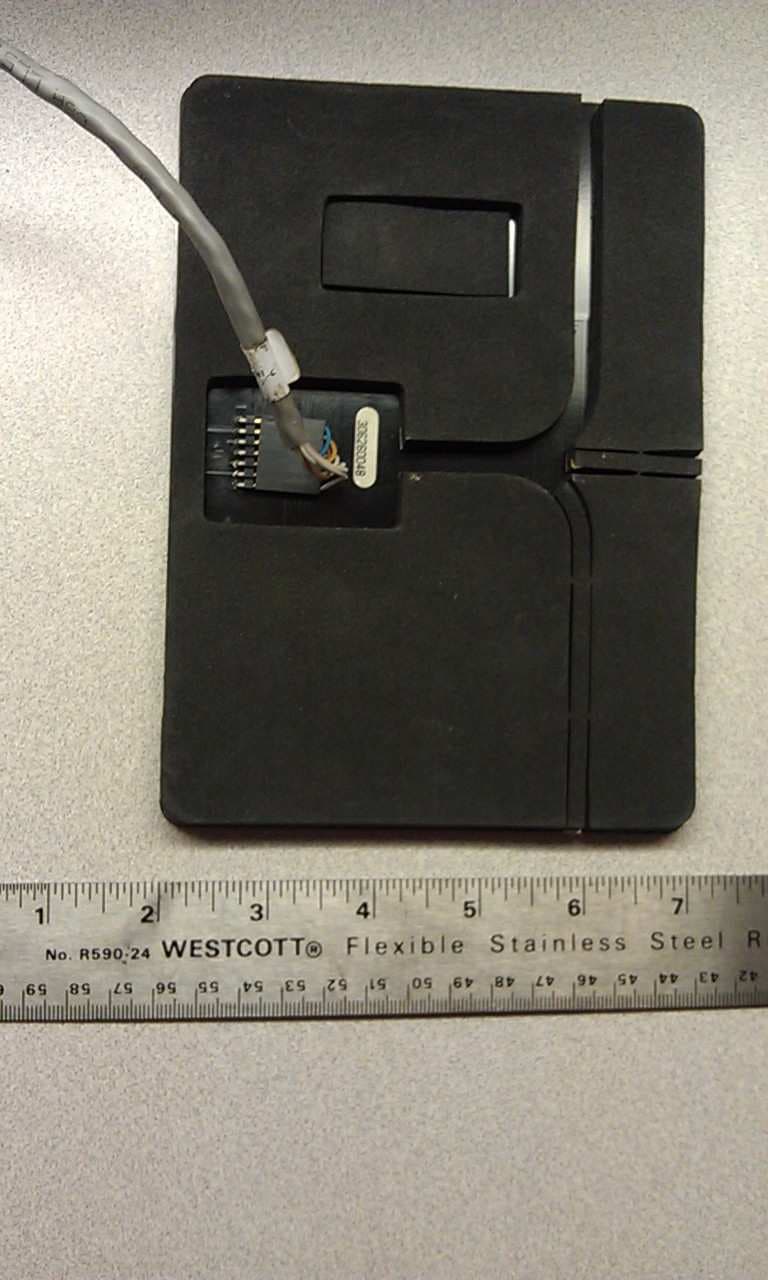
N6SLFMAT
Aug 12, 2013Mat Reader
Equipment Class
DCD - Part 15 Low Power Transmitter Below 1705 kHz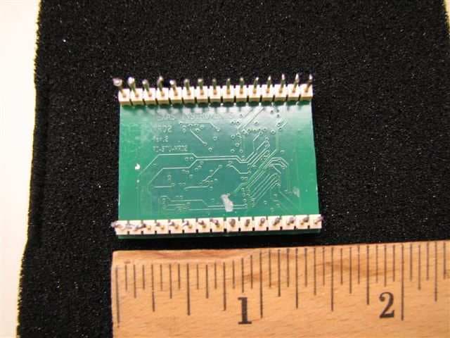
N6SLFECIM
Mar 26, 2013RFID Module
Equipment Class
DCD - Part 15 Low Power Transmitter Below 1705 kHz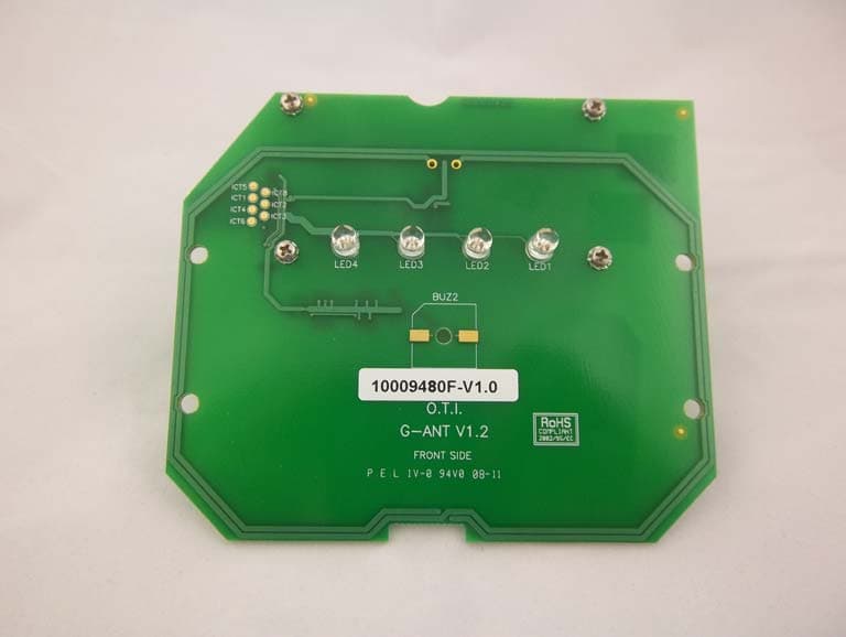
N6SGCM
May 24, 2011Contactless Smart Card Interface
Equipment Class
DXX - Part 15 Low Power Communication Device Transmitter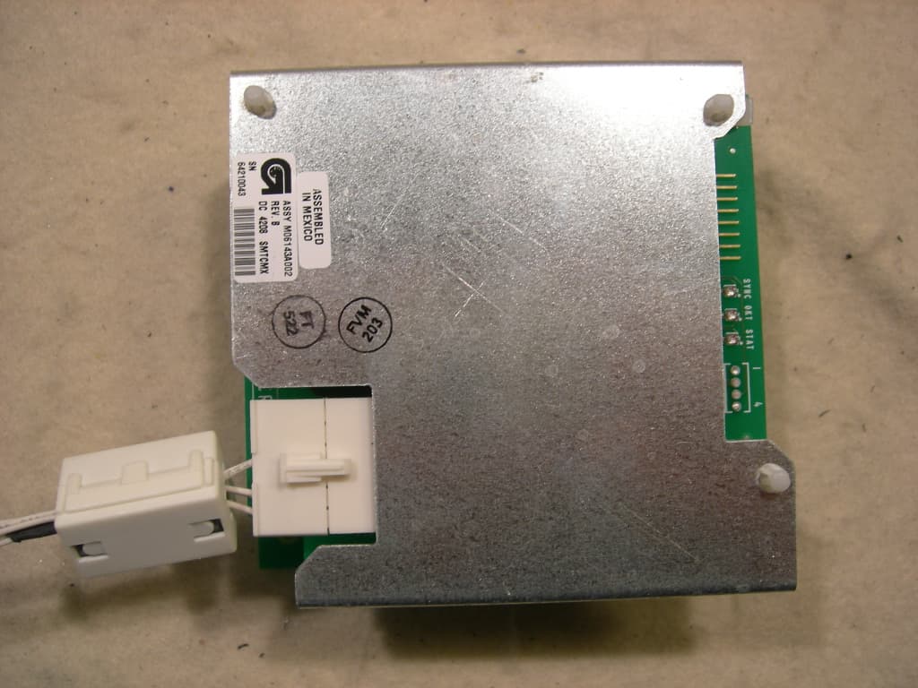
N6SLFTRIND
Jun 10, 2010TRIND RFID Module
Equipment Class
DCD - Part 15 Low Power Transmitter Below 1705 kHz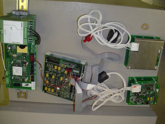
N6SGBIR15
Feb 01, 2006RFID Reader
Equipment Class
DXX - Part 15 Low Power Communication Device Transmitter