N6SLFTRINDTRIND RFID Module
Gilbarco Inc.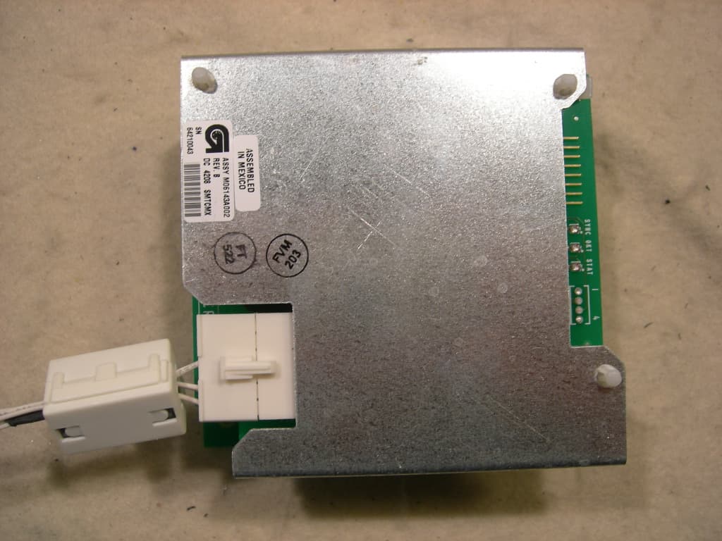
Click to zoom
Application Details
- Equipment Class
- DCD - Part 15 Low Power Transmitter Below 1705 kHz
- Date of Grant
- Jun 10, 2010
- Application Purpose
- Original Equipment
- Date of Application
- Jun 10, 2010
- Equipment Note
- TRIND RFID Module
- Frequency Range
- 0.13420000 - 0.13420000
- Company
- Gilbarco Inc.
- Country
- United States
Documents & Files
Document Text
Text extracted from the exhibit documents filed with the FCC. Open a document above to read the original.
Users Manual
5015 B.U. Bowman Drive Buford, GA 30518 USA Voice: 770-831-8048 Fax: 770-831-8598 Certification Exhibit FCC ID: N6SLFTRIND IC: 827B-LFTRIND FCC Rule Part: 15.209 IC Radio Standards Specification: RSS-210 ACS Report Number: 10-0134.W06.11.A Manufacturer: Gilbarco Inc. Model: LFTRIND Manual MDE-4909 FlexPay™ Unattended Payment Terminal (UPT) TRIND® Retrofit Kit Installation Manual · June 2010Page 1 Pre limin ar y 06 /10 /1 0 Introduction Purpose This manual provides instructions for installing the Transmitter/Receiver IN Dispenser (TRIND ® ) Retrofit Kits in Encore ® S Series units that contain the FlexPay ™ Unattended Payment Terminal (UPT). The TRIND option allows the customer to automatically authorize the units equipped with Card Reader IN Dispenser (CRIND ® ) device, using a low frequency hand-held Transponder Tag provided by a Major Oil Company (MOC) or retailer. This equipment has been tested and found to comply with the limits for a Class A digital device pursuant to Part 15 of the Federal Communications Commission (FCC) Rules. These limits are designed to provide reasonable protection against harmful interference when the equipment is operated in a commercial environment. This equipment generates, uses and can radiate radio frequency energy, and if not installed and used in accordance with the instruction manual, may cause harmful interference to radio communications. Operation of this equipment in a residential area may cause harmful interference in that case the user must be required to correct the interference at his own expense. Changes or modifications not expressly approved by the manufacturer could void the user’s authority to operate this equipment. The long term characteristics or the possible physiological effects of radio frequency electromagnetic fields have not yet been investigated by Underwriters’ Laboratories, Incorporated (UL ® ). Industry Canada-specific Statements: The term “IC:” before the radio certification number only signifies that Industry Canada technical specifications were met. This Class A digital apparatus meets all requirements of the Canadian Interference Causing Equipment Regulations. Operation is subject to the following two conditions: (1) this device may not cause harmful interference, and (2) this device must accept any interference received, including interference that may cause undesired operation. Cet appareillage numérique de la classe A répond à toutes les exigences de l'interférence canadienne causant des règlements d'équipement. L'opération est sujette aux deux suivantes: (1) ce dispositif peut ne pas causer l'interférence nocive, et (2) ce dispositif doit accepter n'importe quelle interférence reçue, y compris l'interférence qui peut causer l'opération peu désirée. IMPORTANT INFORMATION MDE-4909 FlexPay ™ Unattended Payment Terminal (UPT) TRIND ® Retrofit Kit Installation Manual June 2010 Page 2 MDE-4909 FlexPay™ Unattended Payment Terminal (UPT) TRIND® Retrofit Kit Installation Manual · June 2010 Introduction P re limina r y Table of Contents TopicPage Introduction1 Parts Lists3 Important Safety Information4 Installation6 Required Reading Before installing the equipment, the installer must read, understand, and follow: • This Manual • National Fire Protection Agency (NFPA) 30A, The Automotive and Marine Service Station Code • NFPA 70, The National Electric Code • Applicable Federal, State, and Local Codes and Regulations Failure to do so may adversely affect the safe use and operation of the equipment. Note: This kit must be installed by a Gilbarco ® Authorized Service Contractor (ASC). Related Documents Document Number TitleGOLD Library MDE-3664TRIND Start-Up, Service, and Parts Manual• CRIND and TRIND • Service Manual MDE-3804Encore and Eclipse ® Series Start-Up/Service Manual• Encore and Eclipse • Service Manual MDE-4516Encore 500 S Series Owner’s ManualEncore and Eclipse MDE-4903FlexPay Startup and Service ManualFlexPay EPP and SCR PT-1736CRIND Card Reader Illustrated Parts ManualParts Manual PT-1936Encore Series Pump and Dispenser Illustrated Parts Manual• Parts Manual • Encore/Eclipse • Encore and Eclipse Installers Recommended Tools To install TRIND Retrofit Kit M06879S00X, the following equipments are required: • Metric Nut Drivers • Standard Nut Drivers • Needle Nose Pliers • Pliers • Pocket Knife • Putty Knife or Scraper • Diagnostic Card (Q12534-170) • Metric Ratchet Set • Standard Ratchet Set • Flat-head Screwdriver • Static Guard Wrist Strap • TRIND Hand-held Test Tag (Transponder Tag) MDE-4909 FlexPay™ Unattended Payment Terminal (UPT) TRIND® Retrofit Kit Installation Manual · June 2010Page 3 Parts Lists P re limina r y Abbreviations and Acronyms Te rmDescription ASCAuthorized Service Contractor CRINDCard Reader IN Dispenser FCCFederal Communications Commission MOCMajor Oil Company NFPANational Fire Protection Agency PCAPrinted Circuit Assembly TRINDTransmitter/Receiver IN Dispenser ULUnderwriters’ Laboratories UPTUnattended Payment Terminal Parts Lists TRIND Retrofit Kit Parts List The following table provides the parts list for the TRIND Retrofit Kit. DescriptionPart NumberQuantity Nut, Metric, FlangeM00414B005 3 Cable, TRIND PowerM06763A0011 Decal, Patent and FCCM02962B0131 Diagram, BlockR207750 Diagram, InterconnectionT206630 Assembly, Light and InductorM06143A00X (see Note 1)2 Lens, TRINDM05987B0012 TRIND GraphicENS0701G00X (see Note 2)2 Card Reader Instructions GraphicENS0702G0102 Screw, Metric M4X8M00419B1178 Screw, Self-Tapping HexQ11677-246 Cable, Light/Multi Protocol R20773-G22 Gasket, TRINDM06010B0022 FlexPay UPT TRIND Retrofit Kit Installation Manual MDE-4909 1 Notes: 1) M06879S001 (for Mobil) contains Light and Inductor Assembly (Red)- M06143A001. M06879S002 (for Exxon) contains Light and Inductor Assembly (Amber)- M06143A002. 2) M06879S001 (for Mobil) contains TRIND Graphic (ENS0701G002). M06879S002 (for Exxon) contains TRIND Graphic (ENS0701G001). <<Please clarify, if these notes must be removed.>> Page 4 M…
Text truncated - open the document above for the full version.
Attestation Statements
Advanced Compliance Solutions TCB 5015 BU Bowman Dr. Buford, GA 30518 UAttestation of compliance modifications to N6SLFTRIND By signing this document, we acknowledge that modification. was made to the LFTRIND RFID module to bring it into compliance with FCC and Industry Canada regulations. The modification consisted of adding a ferrite (Steward part number 28A2025-0A0) to the power/data cable. We attest that the product will have this modification incorporated when manufactured and placed on the market. Dated this 4th day of May 2010. By: Bob Sykes Title: EMC Engineer email: [email protected] On behalf of: Gilbarco Inc. (Company Name) Telephone: 336-547-5373 Gilbarco Inc. Veede r-Root Company 7300 West Friendly Avenue PO Box 22087 Greensboro, NC 27420-2087 United States Phone: 336-547-5373 Fax: 336-292-8871 Email: [email protected] www.gilbarco.com www.veeder.com
Cover Letter(s)
5015 B. U. Bowman Dr. Buford, GA 30518 May 6, 2010 ACS TCB 5015 B.U. Bowman Drive Buford, GA 30518 Re: FCC ID: N6SLFTRIND To Whom It May Concern: The following application is submitted on behalf of our client, Gilbarco Inc., for evaluation of their model LFTRIND for certification under FCC Part 15.209. The LFTRIND is a stand-alone module which is designed to be integrated into specific host devices. The LFTRIND was tested in full to the requirements of the aforementioned rules and was found to be in compliance. Sincerely, Sam Wismer Vice President, Technology Advanced Compliance Solutions, Inc.
Cover Letter(s)
Gilbarco Inc. Veede r-Root Company 7300 West Friendly Avenue PO Box 22087 Greensboro, NC 27420-2087 United States Phone: 336-547-5373 Fax: 336-292-8871 Email: [email protected] www.gilbarco.com www.veeder.com Attn: Director of Certification Authority to Act as Agent To Whom It May Concern: Please be advised that Gilbarco authorizes Sam Wismer to act on our behalf, until otherwise notified, for applications submitted to the FCC. Gilbarco Inc.’s FRN number is 0003-7489-28. We certify that we are not subject to denial of federal benefits, that includes FCC benefits, pursuant to Section 5301 of the Anti- Drug Abuse ACT of 1988, U.S.C. 862. Further, no party, as defined in 47 CFR 1.2002(b), to the application is subject to denial of federal benefits, that includes FCC benefits. Dated this 30th day of April, 2010. Agency Agreement Expiration Date: 30 April, 2011 By: Bob Sykes Title: EMC Engineer On behalf of: Gilbarco Inc. (Company Name) Telephone: 336-547-5373
Cover Letter(s)
Advanced Compliance Solutions – 5015 B.U. Bowman Drive, Buford, GA 30518 Phone: (770) 831-8048 Fax: (770) 831-8598 May 18, 2010 Federal Communications Commission Equipment Authorization Branch 7435 Oakland Mills Road Columbia, MD 21046 Gentlemen: Gilbarco Inc. respectfully requests confidentiality of certain materials provided with the submission of the LFTRIND under FCC ID: N6SLFTRIND in accordance with FCC Regulations 0.459. The confidentiality request applies to the following exhibits: 10-0134 – Schematics.pdf 10-0134 – System Block Diagram.pdf 10-0134 – Theory of Operation.pdf The LFTRIND has been developed at considerable effort and expense by Gilbarco Inc.. These items are considered as Trade Secrets and therefore public access to the proprietary material could possibly result in duplication of equipment that could severely damage the company’s business advantage. I appreciate your assistance in this matter. Sincerely, Sam Wismer Vice President, Technology Agent
Cover Letter(s)
Gilbarco Inc. Veede r-Root Company 7300 West Friendly Avenue PO Box 22087 Greensboro, NC 27420-2087 United States Phone: 336-547-5373 Fax: 336-292-8871 Email: [email protected] www.gilbarco.com www.veeder.com Request for Modular Approval Date May 4, 2010 Federal Communications Commission Office of Engineering and Technology Equipment Authorization Division 7345 Oakland Mills Rd. Columbia Maryland 21046 RE: Certification Application FCC ID N6SLFTRIND To Whom It May Concern: In reference to FCC ID N6SLFTRIND, Gilbarco is requesting Modular Approval. The numbered requirements for Modular Approval are addressed below 1. The modular transmitter must have its own RF shielding. This is intended to ensure that the module does not have to rely upon the shielding provided by the device into which it is installed in order for all modular transmitter emissions to comply with Part 15 limits. It is also intended to prevent coupling between the RF circuitry of the module and any wires or circuits in the device into which the module is installed. Such coupling may result in non-compliant operation. The Light/MicroReader/Antenna assembly, (p/n M06143) includes a formed sheet metal shield, (p/n M06567), which was designed to provide mechanical and electrical protection for the assembly when installed. 2. The modular transmitter must have buffered modulation/data inputs (if such inputs are provided) to ensure that the module will comply with Part 15 requirements under conditions of excessive data rates or over-modulation. The modular transmitter has two serial data lines to the M06143 Light/MicroReader/Antenna assembly. These lines pass transponder serial numbers and on/off commands for the recognition light. There are no commands from the host device that can change performance and RFID functionality of the Texas Instruments MicroReader on the M06143 assembly. One TTL line connects the module PCA to the fuel dispenser. It passes transponder serial number and authentication code to the dispenser electronics for communication to the point-of-sale (POS) system for credit verification. Once the credit is verified, the POS system instructs the transmitter module to keep the recognition light on or to shut it off. 3. The modular transmitter must have its own power supply regulation. This is intended to ensure that the module will comply with Part 15 requirements regardless of the design of the power supplying circuitry in the device into which the module is installed. The M06143 assembly includes a regulated switching power supply as part of the M06100 PCA. This power supply down converts the +24VDC supplied by the dispenser electronics to the +5VDC required by all components of the modular transmitter system. (The +24VDC from the dispenser is connected to the M06143 assembly where the regulation occurs). The regulated +5VDC is then available to feed the MicroReader and associated circuitry of the intentional radiator on the M06100 PCA. 4. The modular transmitter must comply with the antenna requirements of Section 15.203 and 15.204(c). The antenna must either be permanently attached or employ a “unique” antenna coupler (at all connections between the module and the antenna, including the cable). Any antenna used with the module must be approved with the module, either at the time of initial authorization or through a Class II permissive change. The “professional installation” provision of Section 15.203 may not be applied to modules. This device employs a unique coupler configuration that depends on the mechanical fastener hardware to also make the electrical connection between the Antenna PCA, p/n M06074 and the circuitry of the intentional radiator electronic on the Light/MicroReader PCA M06100. This physical and electrical connection is permanent; the system is rendered inoperable if any modification of the physical connection is attempted. 5. The modular transmitter must be tested in a stand-alone configuration, i.e., the module must not be inside another device during testing. This is intended to demonstrate that the module is capable of complying with Part 15 emission limits regardless of the device into which it is eventually installed. Unless the transmitter module will be battery powered, it must comply with the AC line conducted requirements found in Section 15.207. AC or DC power lines and data input/output lines connected to the module must not contain ferrites, unless they will be marketed with the module (see Section 15.27(a)). The length of these lines shall be length typical of actual use or, if that length is unknown, at least 10 centimeters to insure that there is no coupling between the case of the module and supporting equipment. Any accessories, peripherals, or support equipment connected to the module during testing shall be unmodified or commercially available (see Section 15.31(i)). As the photographs and report indicates, the device was tested in a stand-alone configuration and not inside another device. It does not contain any ferrites that will not be marketed with the module. The device was tested with cables of a length typical of actual use that are greater than 10 centimeters long. The support equipment connected to the module via RS-232 com port for testing purposes was an unmodified Dell laptop PC. 6. The modular transmitter must be labeled with its own FCC ID number, and, if the FCC ID is not visible when the module is installed inside another device, then the outside of the device into which the module is installed must also display a label referring to the enclosed module. This exterior label can use wording such as the following: “Contains Transmitter Module FCC ID: XYZMODEL1” or “Contains FCC ID: XYZMODEL1.” Any similar wording that expresses the same meaning may be used. The Grantee may either provide such a label, an example of which must be included in the application for equipment authorization, or, must provide adequate instructions along with the module which ex…
Text truncated - open the document above for the full version.
External Photos
5015 B.U. Bowman Drive Buford, GA 30518 USA Voice: 770-831-8048 Fax: 770-831-8598 Certification Exhibit FCC ID: N6SLFTRIND IC: 827B-LFTRIND FCC Rule Part: 15.209 IC Radio Standards Specification: RSS-210 ACS Report Number: 10-0134.W06.11.A Manufacturer: Gilbarco Inc. Model: LFTRIND External Photos Model(s): LFTRIND FCC ID: N6SLFTRIND IC: 827B-LFTRIND Figure 1: Top View ACS Report: 10-0134.W06.11.A Advanced Compliance Solutions Page 2 Model(s): LFTRIND FCC ID: N6SLFTRIND IC: 827B-LFTRIND Figure 2: Bottom View ACS Report: 10-0134.W06.11.A Advanced Compliance Solutions Page 3 Model(s): LFTRIND FCC ID: N6SLFTRIND IC: 827B-LFTRIND Figure 3: Side 1 View ACS Report: 10-0134.W06.11.A Advanced Compliance Solutions Page 4 Model(s): LFTRIND FCC ID: N6SLFTRIND IC: 827B-LFTRIND ACS Report: 10-0134.W06.11.A Advanced Compliance Solutions Page 5 Figure 4: Side 2 View
ID Label/Location Info
5015 B.U. Bowman Drive Buford, GA 30518 USA Voice: 770-831-8048 Fax: 770-831-8598 Certification Exhibit FCC ID: N6SLFTRIND IC: 827B-LFTRIND FCC Rule Part: 15.209 IC Radio Standards Specification: RSS-210 ACS Report Number: 10-0134.W06.11.A Manufacturer: Gilbarco Inc. Model: LFTRIND Label Information Model(s): LFTRIND FCC ID: N6SLFTRIND IC: 827B-LFTRIND ACS Report: 10-0134.W06.11.A Advanced Compliance Solutions Page 2 Figure 1: Sample Label Figure 2: Label Location Figure 3: Host Sample Label
Internal Photos
5015 B.U. Bowman Drive Buford, GA 30518 USA Voice: 770-831-8048 Fax: 770-831-8598 Certification Exhibit FCC ID: N6SLFTRIND IC: 827B-LFTRIND FCC Rule Part: 15.209 IC Radio Standards Specification: RSS-210 ACS Report Number: 10-0134.W06.11.A Manufacturer: Gilbarco Inc. Model: LFTRIND Internal Photos Model(s): LFTRIND FCC ID: N6SLFTRIND IC: 827B-LFTRIND Figure 1: PCB with Shields - Front ACS Report: 10-0134.W06.11.A Advanced Compliance Solutions Page 2 Model(s): LFTRIND FCC ID: N6SLFTRIND IC: 827B-LFTRIND Figure 2: PCB without Shields - Front ACS Report: 10-0134.W06.11.A Advanced Compliance Solutions Page 3 Model(s): LFTRIND FCC ID: N6SLFTRIND IC: 827B-LFTRIND ACS Report: 10-0134.W06.11.A Advanced Compliance Solutions Page 4 Figure 3: PCB - Back
Test Report
5015 B.U. Bowman Drive Buford, GA 30518 USA Voice: 770-831-8048 Fax: 770-831-8598 Certification Test Report FCC ID: N6SLFTRIND IC: 827B-LFTRIND FCC Rule Part: 15.209 IC Radio Standards Specification: RSS-210 ACS Report Number: 10-0134.W06.11.A Manufacturer: Gilbarco Inc. Model: LFTRIND Test Begin Date: April 21, 2010 Test End Date: April 21, 2010 Report Issue Date: May 3, 2010 FOR THE SCOPE OF ACCREDITATION UNDER LAB Code 200612-0 This report is not be used to claim certification, approval, or endorsement by NVLAP, NIST or any government agency. Reviewed by: Kirby Munroe Director, Wireless Certifications ACS, Inc. This test report shall not be reproduced except in full. This report may be reproduced in part with prior written consent of ACS, Inc. The results contained in this report are representative of the sample(s) submitted for evaluation. This report contains 16 pages 5015 B.U. Bowman Drive Buford, GA 30518 USA Voice: 770-831-8048 Fax: 770-831-8598 TABLE OF CONTENTS 1 GENERAL ............................................................................................................................................ 3 1.1 PURPOSE .......................................................................................................................................... 3 1.2 PRODUCT DESCRIPTION ................................................................................................................... 3 1.3 TEST METHODOLOGY AND CONSIDERATIONS ................................................................................. 3 2 TEST FACILITIES .............................................................................................................................. 4 2.1 LOCATION ....................................................................................................................................... 4 2.2 LABORATORY ACCREDITATIONS/RECOGNITIONS/CERTIFICATIONS ................................................ 4 2.3 RADIATED EMISSIONS TEST SITE DESCRIPTION .............................................................................. 5 2.3.1 Semi-Anechoic Chamber Test Site .......................................................................................... 5 2.3.2 Open Area Tests Site (OATS) ................................................................................................. 6 2.4 CONDUCTED EMISSIONS TEST SITE DESCRIPTION ........................................................................... 7 3 APPLICABLE STANDARD REFERENCES .................................................................................... 7 4 LIST OF TEST EQUIPMENT ............................................................................................................ 8 5 SUPPORT EQUIPMENT .................................................................................................................... 9 6 EQUIPMENT UNDER TEST SETUP BLOCK DIAGRAM ........................................................... 9 7 SUMMARY OF TESTS ..................................................................................................................... 10 7.1 ANTENNA REQUIREMENT – FCC: SECTION 15.203 ....................................................................... 10 7.2 POWER LINE CONDUCTED EMISSIONS – FCC: SECTION 15.207 IC: RSS-GEN 7.2.2 ...................... 10 7.2.1 Measurement Procedure ....................................................................................................... 10 7.2.2 Measurement Results ............................................................................................................ 10 7.3 RADIATED EMISSIONS – FCC CFR 47 PART 15.209 / RSS-210 SECTION 2.6................................. 12 7.3.1 Measurement Procedure ....................................................................................................... 12 7.3.2 Distance Correction for Measurements Below 30 MHz – Part 15.31 .................................. 12 7.3.3 Measurement Results ............................................................................................................ 13 7.3.4 Sample Calculation ............................................................................................................... 14 7.4 20DB / 99% BANDWIDTH – FCC: SECTION 15.215(C) / IC: RSS-210 SECTION 4.6.1 ..................... 14 7.4.1 Measurement Procedure ....................................................................................................... 14 7.4.2 Measurement Results ............................................................................................................ 14 8 CONCLUSION ................................................................................................................................... 16 Model: LFTRIND FCC ID: N6SLFTRIND IC: 827B-LFTRIND ACS Report: 10-0134.W06.11.A Advanced Compliance Solutions Page 3 1 GENERAL 1.1 Purpose The purpose of this report is to demonstrate compliance with Part 15 Subpart C of the FCC’s Code of Federal Regulations and Industry Canada’s Radio Standards Specification RSS-210. 1.2 Product description The TRIND™ is a Radio Frequency Identification Device (RFID) which is designed for use in conjunction with passive transponders (not requiring a battery), Texas Instruments Part # RI- TRP-Series. Technical Details: Frequency Range: 134.2 kHz Operating channels: 1 Modulation: FSK Operating Voltage: 24 VDC Manufacturer Information: Gilbarco Inc. 7300 West Friendly Ave. Greensboro NC 27420 Test Sample Serial Number(s): 9758760 Test Sample Condition: The test samples were provided in good working order with no visible defects. 1.3 Test Methodology and Considerations In order to comply with 15.109 regulations, the LFTRIND needed a ferrite placed on the power/data cable. The part number of the ferrite used was Steward Ferrite 28A2025-0A0. See attestation letter for details. Model: LFTRIND FCC ID: N6SLFTRIND IC: 827B-LFTRIND ACS Report: 10-0134.W06.11.A Advanced Compliance Solutions Pa…
Text truncated - open the document above for the full version.
Test Setup Photos
5015 B.U. Bowman Drive Buford, GA 30518 USA Voice: 770-831-8048 Fax: 770-831-8598 Certification Exhibit FCC ID: N6SLFTRIND IC: 827B-LFTRIND FCC Rule Part: 15.209 IC Radio Standards Specification: RSS-210 ACS Report Number: 10-0134.W06.11.A Manufacturer: Gilbarco Inc. Model: LFTRIND Test Setup Photos Model(s): LFTRIND FCC ID: N6SLFTRIND IC: 827B-LFTRIND Figure 1: Radiated Emissions ACS Report: 10-0134.W06.11.A Advanced Compliance Solutions Page 2 Model(s): LFTRIND FCC ID: N6SLFTRIND IC: 827B-LFTRIND Figure 2: Radiated Emissions ACS Report: 10-0134.W06.11.A Advanced Compliance Solutions Page 3 Model(s): LFTRIND FCC ID: N6SLFTRIND IC: 827B-LFTRIND Figure 3: Radiated Emissions ACS Report: 10-0134.W06.11.A Advanced Compliance Solutions Page 4 Model(s): LFTRIND FCC ID: N6SLFTRIND IC: 827B-LFTRIND Figure 4: Conducted Emissions ACS Report: 10-0134.W06.11.A Advanced Compliance Solutions Page 5 Model(s): LFTRIND FCC ID: N6SLFTRIND IC: 827B-LFTRIND ACS Report: 10-0134.W06.11.A Advanced Compliance Solutions Page 6 Figure 5: Conducted Emissions
Contact Information
Applicant
Bob Sykes(EMC Engineer)
Test Firm
Advanced Compliance Solutions, Inc.Sam Wismer
Technical Specifications
| # | Rule Parts | Frequency Range | Power Output |
|---|---|---|---|
| 1 | 15C | 0.1342 MHz - 0.1342 MHz | - |
Other Applications from Gilbarco Inc.
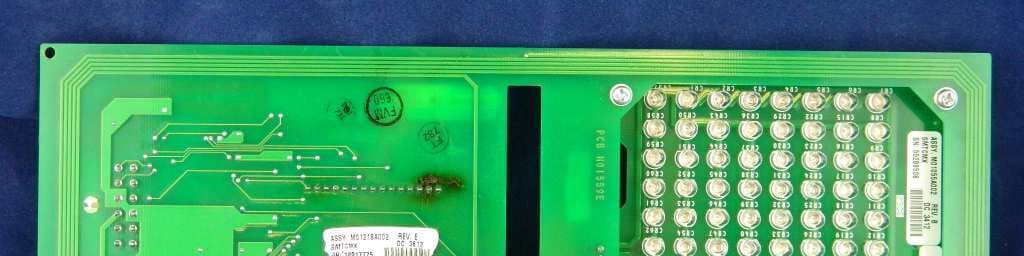
N6SLFSQR
Jun 23, 2015TRIND M01560 Module
Equipment Class
DCD - Part 15 Low Power Transmitter Below 1705 kHz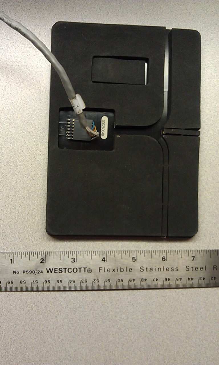
N6SLFMAT
Aug 12, 2013Mat Reader
Equipment Class
DCD - Part 15 Low Power Transmitter Below 1705 kHz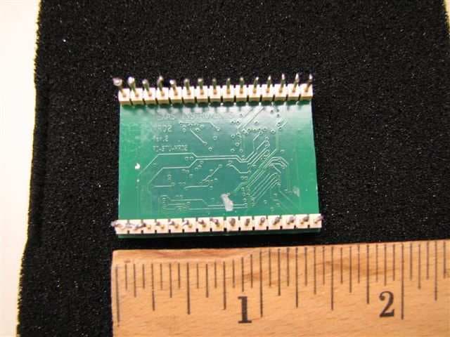
N6SLFECIM
Mar 26, 2013RFID Module
Equipment Class
DCD - Part 15 Low Power Transmitter Below 1705 kHz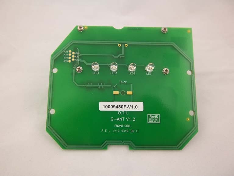
N6SGCM
May 24, 2011Contactless Smart Card Interface
Equipment Class
DXX - Part 15 Low Power Communication Device Transmitter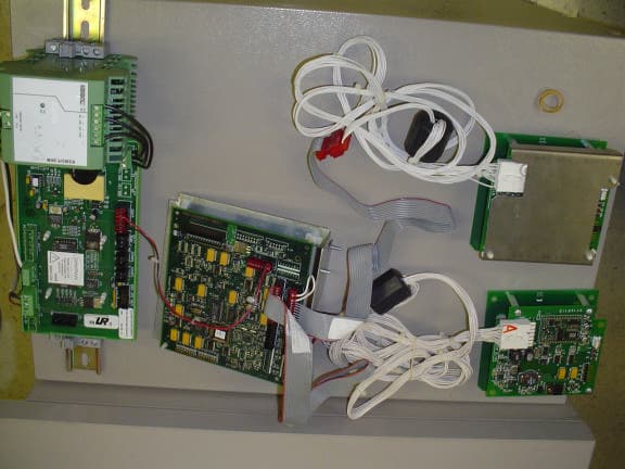
N6SGBIR15
Feb 01, 2006RFID Reader
Equipment Class
DXX - Part 15 Low Power Communication Device Transmitter