N6SLFECIMRFID Module
Gilbarco Inc.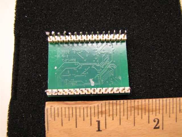
Click to zoom
Application Details
- Equipment Class
- DCD - Part 15 Low Power Transmitter Below 1705 kHz
- Date of Grant
- Mar 26, 2013
- Application Purpose
- Original Equipment
- Date of Application
- Mar 26, 2013
- Equipment Note
- RFID Module
- Frequency Range
- 0.13400000 - 0.13400000
- Company
- Gilbarco Inc.
- Country
- United States
Documents & Files
Document Text
Text extracted from the exhibit documents filed with the FCC. Open a document above to read the original.
Users Manual
5015 B.U. Bowman Drive Buford, GA 30518 USA Voice: 770-831-8048 Fax: 770-831-8598 Certification Exhibit FCC ID: N6SLFECIM IC: 827B-LFECIM FCC Rule Part: 15.209 IC Radio Standards Specification: RSS-210 ACS Project Number: 13-0074 Manufacturer: Gilbarco Inc. Model: LFECIM Manual P rel i m i nary 0 3/ 22 /1 3 The Advantage ® Series, MPD ® -3, Encore ® , and Eclipse ® Units TRIND ® Start-Up, Service, and Parts Manual MDE-3664B C-PAM ™ Horizon ™ SurgeManagementSystem ™ e-CRIND ® Making Things Better ® Trimline ® ECR ™ MultiLine ™ Tank Monitor ™ Eclipse ® MPD ® TRIND ® EMC ™ Optimum ™ SeriesTCR ™ Encore ® Passport ® VaporVac ® FlexPay ™ PAM ™ 1000Titan ™ G-SITE ® Performer ® G-CAT ™ PAM ™ Ultra-Hi ™ Gilbarco ® The Advantage ® Series Gilbert ™ G-SITE ® Link ™ SMART Connect ™ SMART CRIND ™ ValueLine ™ Computer Programs and Documentation All Gilbarco Inc. and/or VeederRoot Company computer programs (including softwareon diskettes and within memory chips)and documentat ion are copyri ghted by, and shall remainthepropertyof,Gilbarco Inc. and/orVeeder Root Company. Suchcomputerprogramsanddocumentsmayalsocontaintrade secretinformation.Theduplicat ion, disclosure, modification, or unauthorized use of computerprograms or documentationis strictly prohibite d, unlessotherwise licensed by Gilbarco Inc. and/or VeederRoot Company. Federal Communications Commission (FCC) Warni ng This equipmentha s been tested and found to comply with the limits fora Class A digitaldevice pursuantto Part 15 of the FCC Rules. These limit saredesigned to provide reasonable protectionagainst harmful interference when the equipment is operated in acommercial environment. This equipmentgenerates, uses, and can radiate radio frequency energy, andif notinstalledandusedin accordancewiththeinstructionmanual,may causeharmful interferencetora diocommunications.Operat ionofthis equipmentin aresident ial areais likelytocaus e harmfulinterferencein whichcasetheuser willberequiredtocorrect the interfe rence athisownexpense. Changesormodificat ionsnotexpresslyapproved by the manufacturercould void theuser’ s authority to operate this equipment. Industry Canada Warning This device complies with Industry Canadalic ence-exemptRSSstandard(s). Operation is subject tothefollowing two condit ions: (1) this devicemay notcause interference, and (2) this devicemust accept any interference, including interferencethat may cause undesired operation of the device. Le présent appareil est conformeaux CNR d'Industr ie Canadaapplicables aux appareilsra dio exempts de licence. L'exploitation est autoriséeaux deux conditions suivantes : (1) l'appareil ne do it pasproduire de brouillage, et (2) l'utilisateur del'appareil doitaccepter tout brouillage radioélectrique subi, mêmesi lebrouillage est susceptible d'enco mpromet trele fonct ionnement. Under Industry Canada regulations, this radio transmitter may only operate using an antenna of a type and maximum (or lesser) gain approved for the transmitter by Industry Canada. To reducepotential radio interference to other users, the antenna type and its gain should be so chosen thatthe equivalent isotropically radiated power (e.i.r.p.) is not more than that necessary for successfulcommunication. Conformément à la réglementation d'Industrie Canada, le présent émetteur radio peutfonctionner avec une antenne d'un type et d'un gain maximal (ou inférieur) approuvé pour l'émetteur par Industrie Canada. Dans le but de réduire les risques de brouillage radioélectrique àl'intention des autres utilisateurs, il faut choisir le type d'antenne et son gain de sorte que lapuissance isotrope rayonnée équivalente (p.i.r.e.) ne dépasse pas l'intensité nécessaire à l'établissement d'une communication satisfaisante. Approvals Gilbarco is anISO 9001:2008 registered company. UnderwritersLaboratories(UL): U LFile#Products listed with U L MH1941 All Gilbarco pumpsand dispensers that bear the UL listing mark. MH8467TransacSystem1000and PAM1000 E105106Dell DHM Minitower E165027G-SITE and Passport Systems CaliforniaAir ResourcesBoard(C ARB): Executive Order# Pr oduct G-70-52-AMBalanceVapor Recovery G-70-150-AEVaporVac NationalConferenceofWeightsand Measures(NCWM)- CertificateofConformance(CoC): Gilbarco pumps and dispensers areevaluated by NCWM under the National Type Evaluat ion Program (NTEP) . NCWM has issued the following CoC: CoC#ProductModel #CoC#ProductModel # 02-019EncoreNxx02-036LegacyJxxx 02-020EclipseExxG-SITE Printer(Epson)PA0307 02-025 Meter- C SeriesPA024NC10G-SITE Distribution BoxPA0306 Meter- C SeriesPA024TC10G-SITE KeyboardPA0304 02-037 02-029CRIND—G-SITE Mini TowerPA0301 TS-1000 Conso le—G-SITE MonitorPA0303 TS-1000 ControllerPA0241G-SITE Printer(Cit izen)PA0308 02-030Distribution BoxPA024202-038C+ MeterT19976 Meter- EC Se riesPA024EC1002-039PassportPA0324 VaporV acKi tsCV02-040EcometerT20453 05-001TitanKXXY Series Trademarks Non-registeredtrademarks Applause ™ Media SystemG-SITE ® Lite ™ SMART Meter ™ CIM ™ Highline ™ SmartPad ™ Registered trademarks CRIND ® InfoScreen ® Tr ansac ® Dimension ® Series Legacy ® Tr ansac ® System 1000 Additional USand forei gn trademarks pending. Otherbrand or productnames shown may be trademarks or registe red trademarksoftheir respective holders. This documentis subject to change wit hout notice. E- mail: literat [email protected] · Internet: http://www.gilbarco.com 2013 Gilbarco Inc. AllRights Reserved MDE-3664B TRIND Start-Up, Service, and Parts Manual . March 2013 Page 1 Table of Contents P re l im i na ry Table of Contents 1 – Introduction 1 TRIND Overview . . . . . . . . . . . . . . . . . . . . . . . . . . . . . . . . . . . . . . . . . . . . . . . . . . . . . . . . . . . . . . . . . . . 1 About TRIND . . . . . . . . . . . . . . . . . . . . . . . . . . . . . . . . . . . . . . . . . . . . . . . 1 How TRIND Works . . . . . . . . . . . . . . . . . . . . . . . . . . . . . . . . . . . . . . . . . . . . . . . . . . . . . . . . . . . . . . . . . 2 Related Documents . . . . . . . . . . . . . . …
Text truncated - open the document above for the full version.
Cover Letter(s)
March 13, 2013 Federal Communications Commission Equipment Authorization Branch 7435 Oakland Mills Road Columbia, MD 21046 Dear Sir or Madam: I hereby appoint Sam Wismer at Advanced Compliance Solutions, Inc. to act as our agent in the preparation of an application for equipment authorization of FCC ID: N6SLFECIM to the FCC Rules and Regulations. I certify that all exhibits contained within this filing properly describe the device or system for which authorization is sought. I further certify that appropriate arrangements have been made to assure that production units of this equipment bearing the name and FCC IDENTIFIER listed in this application will continue to comply with the Commission's requirements. I further certify by signature below that no party (per 47 CFR 1.2002(b)) to the application is subject to a denial of Federal benefits, including FCC benefits, pursuant to Section 5301 of the Anti-Drug Abuse Act of 1988, 21 U.S.C. 853(a). This appointment also includes the authority to complete FCC Form 731 on our behalf and sign the application as an authorized agent. Sincerely, Bob Sykes Title: EMC Engineer On behalf of: Gilbarco Inc. (Company Name) Telephone: 336-547-5373
Cover Letter(s)
Request for Confidentiality Date March 18, 2013 Federal Communications Commission Office of Engineering and Technology Equipment Authorization Division 7345 Oakland Mills Rd. Columbia Maryland 21046 RE: Certification Application FCC ID N6SLFECIM To Whom It May Concern: In reference to FCC ID N6SLFECIM, Gilbarco is requesting confidentiality for the following: Schematic diagrams System Block diagram System functional/operation description This request is being made under the provisions of Section 0.457(d) of the Commission’s rules, and Section 552(b)(4) of the Freedom of Information Act. These schematic diagrams should fall within the scope of Section 552(b)(4) as trade secrets, under the provisions of Section 0.457(d), these schematic diagrams should not be routinely available for public inspection. The application contains technical information, which Gilbarco deems to be trade secrets and proprietary. If made public, the information might be used to the disadvantage of the applicant in the market place. Thank you for your attention to this matter. Bob Sykes EMC Engineer
Cover Letter(s)
5015 B. U. Bowman Dr. Buford, GA 30518 March 22, 2013 ACS TCB 5015 B.U. Bowman Drive Buford, GA 30518 Re: FCC ID: N6SLFECIM To Whom It May Concern: The following application is submitted on behalf of our client, Gilbarco Inc., for evaluation of their model LFECIM for single modular approval certification under FCC Part 15.209. The model LFECIM is a Radio Frequency Identification Device (RFID) which is designed for use in conjunction with passive transponders (not requiring a battery), Texas Instruments Part # RI-TRP-Series. The user carries the handheld transponder and the transmitter portion of the LFECIM operates at 134.2kHz. The LFECIM was tested in full to the requirements of the aforementioned rules and was found to be in compliance. Sincerely, Sam Wismer Vice President, Technology Advanced Compliance Solutions, Inc.
Cover Letter(s)
Request for Modular Approval Date March 18, 2013 Federal Communications Commission Office of Engineering and Technology Equipment Authorization Division 7345 Oakland Mills Rd. Columbia Maryland 21046 RE: Certification Application FCC ID N6SLFECIM To Whom It May Concern: In reference to FCC ID N6SLFECIM, Gilbarco is requesting Modular Approval. The numbered requirements for Modular Approval are addressed below 1. The modular transmitter must have its own RF shielding. This is intended to ensure that the module does not have to rely upon the shielding provided by the device into which it is installed in order for all modular transmitter emissions to comply with Part 15 limits. It is also intended to prevent coupling between the RF circuitry of the module and any wires or circuits in the device into which the module is installed. Such coupling may result in non-compliant operation. The Light/MicroReader/Antenna assembly, (p/n M06143) includes a formed sheet metal shield, (p/n M06567), which was designed to provide mechanical and electrical protection for the assembly when installed. 2. The modular transmitter must have buffered modulation/data inputs (if such inputs are provided) to ensure that the module will comply with Part 15 requirements under conditions of excessive data rates or over-modulation. The modular transmitter has two serial data lines to the M06143 Light/MicroReader/Antenna assembly. These lines pass transponder serial numbers and on/off commands for the recognition light. There are no commands from the host device that can change performance and RFID functionality of the Texas Instruments MicroReader on the M06143 assembly. One TTL line connects the module PCA to the fuel dispenser. It passes transponder serial number and authentication code to the dispenser electronics for communication to the point-of-sale (POS) system for credit verification. Once the credit is verified, the POS system instructs the transmitter module to keep the recognition light on or to shut it off. 3. The modular transmitter must have its own power supply regulation. This is intended to ensure that the module will comply with Part 15 requirements regardless of the design of the power supplying circuitry in the device into which the module is installed. The M06143 assembly includes a regulated switching power supply as part of the M06100 PCA. This power supply down converts the +24VDC supplied by the dispenser electronics to the +5VDC required by all components of the modular transmitter system. (The +24VDC from the dispenser is connected to the M06143 assembly where the regulation occurs). The regulated +5VDC is then available to feed the MicroReader and associated circuitry of the intentional radiator on the M06100 PCA. The MicroReader further regulates its input from a range of 5.5-2.7VDC to the internal voltages required by the MicrReader. 4. The modular transmitter must comply with the antenna requirements of Section 15.203 and 15.204(c). The antenna must either be permanently attached or employ a “unique” antenna coupler (at all connections between the module and the antenna, including the cable). Any antenna used with the module must be approved with the module, either at the time of initial authorization or through a Class II permissive change. The “professional installation” provision of Section 15.203 may not be applied to modules. This device employs a unique coupler configuration that depends on the mechanical fastener hardware to also make the electrical connection between the Antenna PCA, p/n M06074 and the circuitry of the intentional radiator electronic on the Light/MicroReader PCA M06100. This physical and electrical connection is permanent; the system is rendered inoperable if any modification of the physical connection is attempted. 5. The modular transmitter must be tested in a stand-alone configuration, i.e., the module must not be inside another device during testing. This is intended to demonstrate that the module is capable of complying with Part 15 emission limits regardless of the device into which it is eventually installed. Unless the transmitter module will be battery powered, it must comply with the AC line conducted requirements found in Section 15.207. AC or DC power lines and data input/output lines connected to the module must not contain ferrites, unless they will be marketed with the module (see Section 15.27(a)). The length of these lines shall be length typical of actual use or, if that length is unknown, at least 10 centimeters to insure that there is no coupling between the case of the module and supporting equipment. Any accessories, peripherals, or support equipment connected to the module during testing shall be unmodified or commercially available (see Section 15.31(i)). As the photographs and report indicates, the device was tested in a stand-alone configuration and not inside another device. It does not contain any ferrites that will not be marketed with the module. The device was tested with cables of a length typical of actual use that are greater than 10 centimeters long. The support equipment connected to the module via RS-232 com port for testing purposes was an unmodified laptop PC. 6. The modular transmitter must be labeled with its own FCC ID number, and, if the FCC ID is not visible when the module is installed inside another device, then the outside of the device into which the module is installed must also display a label referring to the enclosed module. This exterior label can use wording such as the following: “Contains Transmitter Module FCC ID: XYZMODEL1” or “Contains FCC ID: XYZMODEL1.” Any similar wording that expresses the same meaning may be used. The Grantee may either provide such a label, an example of which must be included in the application for equipment authorization, or, must provide adequate instructions along with the module which explain this requirement. In the latter case, a copy of these instructions must be included in t…
Text truncated - open the document above for the full version.
External Photos
5015 B.U. Bowman Drive Buford, GA 30518 USA Voice: 770-831-8048 Fax: 770-831-8598 Certification Exhibit FCC ID: N6SLFECIM IC: 827B-LFECIM FCC Rule Part: 15.209 IC Radio Standards Specification: RSS-210 ACS Project Number: 13-0074 Manufacturer: Gilbarco Inc. Model: LFECIM External Photos Model: LFECIMFCC ID: N6SLFECIMIC: 827B-LFECIM ACS Project: 13-0074Advanced Compliance SolutionsPage 2 Figure 1: External Photo Figure 2: External Photo Model: LFECIMFCC ID: N6SLFECIMIC: 827B-LFECIM ACS Project: 13-0074Advanced Compliance SolutionsPage 3 Figure 3: External Photo Figure 4: External Photo
ID Label/Location Info
5015 B.U. Bowman Drive Buford, GA 30518 USA Voice: 770-831-8048 Fax: 770-831-8598 Certification Exhibit FCC ID: N6SLFECIM IC: 827B-LFECIM FCC Rule Part: 15.209 IC Radio Standards Specification: RSS-210 ACS Project Number: 13-0074 Manufacturer: Gilbarco Inc. Model: LFECIM Label Information Model: LFECIMFCC ID: N6SLFECIMIC: 827B-LFECIM ACS Project: 13-0074Advanced Compliance SolutionsPage 2 Figure 1: Sample Label Figure 2: Label Placement Model: LFECIMFCC ID: N6SLFECIMIC: 827B-LFECIM ACS Project: 13-0074Advanced Compliance SolutionsPage 3 Figure 3: Sample Host Label
Internal Photos
5015 B.U. Bowman Drive Buford, GA 30518 USA Voice: 770-831-8048 Fax: 770-831-8598 Certification Exhibit FCC ID: N6SLFECIM IC: 827B-LFECIM FCC Rule Part: 15.209 IC Radio Standards Specification: RSS-210 ACS Project Number: 13-0074 Manufacturer: Gilbarco Inc. Model: LFECIM Internal Photos Model: LFECIMFCC ID: N6SLFECIMIC: 827B-LFECIM ACS Project: 13-0074Advanced Compliance SolutionsPage 2 Figure 1: Internal Photo – Shield Removed Figure 2: Internal Photo Model: LFECIMFCC ID: N6SLFECIMIC: 827B-LFECIM ACS Project: 13-0074Advanced Compliance SolutionsPage 3 Figure 3: Internal Photo – Transceiver Module Figure 4: Internal Photo – Transceiver Module Model: LFECIMFCC ID: N6SLFECIMIC: 827B-LFECIM ACS Project: 13-0074Advanced Compliance SolutionsPage 4 Figure 5: Internal Photo – Antenna Figure 6: Internal Photo – Antenna
Test Report
5015 B.U. Bowman Drive Buford, GA 30518 USA Voice: 770-831-8048 Fax: 770-831-8598 Certification Test Report FCC ID: N6SLFECIM IC: 827B-LFECIM FCC Rule Part: 15.209 IC Radio Standards Specification: RSS-210 ACS Report Number: 13-0074.W06.1A Manufacturer: Gilbarco Inc. Model: LFECIM Test Begin Date: February 23, 2013 Test End Date: March 6, 2013 Report Issue Date: March 22, 2013 FOR THE SCOPE OF ACCREDITATION UNDER LAB Code 200612-0 This report must not be used by the client to claim product certification, approval, or endorsement by NVLAP, NIST, or any agency of the Federal Government. Reviewed by: Kirby Munroe Director, Wireless Certifications ACS, Inc. This test report shall not be reproduced except in full. This report may be reproduced in part with prior written consent of ACS, Inc. The results contained in this report are representative of the sample(s) submitted for evaluation. This report contains 16 pages 5015 B.U. Bowman Drive Buford, GA 30518 USA Voice: 770-831-8048 Fax: 770-831-8598 TABLE OF CONTENTS 1GENERAL ............................................................................................................................................ 3 1.1PURPOSE.......................................................................................................................................... 3 1.2PRODUCT DESCRIPTION................................................................................................................... 3 1.3TESTMETHODOLOGY ANDCONSIDERATIONS................................................................................. 3 2TEST FACILITIES.............................................................................................................................. 4 2.1LOCATION....................................................................................................................................... 4 2.2LABORATORYACCREDITATIONS/RECOGNITIONS/CERTIFICATIONS................................................ 4 2.3RADIATEDEMISSIONSTESTSITEDESCRIPTION.............................................................................. 5 2.3.1Semi-Anechoic Chamber Test Site .......................................................................................... 5 2.3.2Open Area Tests Site (OATS) ................................................................................................. 6 2.4CONDUCTEDEMISSIONSTESTSITEDESCRIPTION........................................................................... 7 3APPLICABLE STANDARD REFERENCES.................................................................................... 7 4LIST OF TEST EQUIPMENT............................................................................................................ 8 5SUPPORT EQUIPMENT .................................................................................................................... 9 6EQUIPMENT UNDER TEST SETUP BLOCK DIAGRAM ........................................................... 9 7SUMMARY OF TESTS ......................................................................................................................10 7.1ANTENNAREQUIREMENT–FCC:SECTION15.203 ........................................................................10 7.2POWERLINECONDUCTEDEMISSIONS–FCC:SECTION15.207IC:RSS-GEN7.2.4.......................10 7.2.1Measurement Procedure........................................................................................................10 7.2.2Measurement Results .............................................................................................................10 7.3RADIATEDEMISSIONS–FCCCFR47PART15.209/RSS-210SECTION2.5..................................11 7.3.1Measurement Procedure........................................................................................................11 7.3.2Distance Correction for Measurements Below 30 MHz – Part 15.31 ...................................12 7.3.3Measurement Results .............................................................................................................12 7.3.4Sample Calculation................................................................................................................13 7.420DB/99%BANDWIDTH–FCC:SECTION15.215,IC:RSS-GEN4.6.1.........................................14 7.4.1Measurement Procedure........................................................................................................14 7.4.2Measurement Results .............................................................................................................14 8CONCLUSION ....................................................................................................................................16 Model: LFECIMFCC ID:N6SLFECIMIC:827B-LFECIM ACS Report: 13-0074.W06.1AAdvanced Compliance SolutionsPage 3 1GENERAL 1.1Purpose The purpose of this report is to demonstrate compliance with Part 15 Subpart C of the FCC’s Code of Federal Regulations and Industry Canada’s Radio Standards Specification RSS-210 for modular approval certification. 1.2Product description The model LFECIM is a Radio Frequency Identification Device (RFID) which is designed for use in conjunction with passive transponders (not requiring a battery), Texas Instruments Part # RI- TRP-Series. The user carries the handheld transponder and the transmitter portion of the LFECIM operates at 134.2kHz. Technical Information: Band of Operation: 134 kHz Number of Channels: 1 Modulation Format: FSK Antenna Type: Integral Loop Operating Voltage: 24 VDC (Host) Manufacturer Information: Gilbarco Inc. 7300 West Friendly Ave. Greensboro NC 27420 Test Sample Serial Number(s): 64219196 Test Sample Condition: The test samples were provided in good working order with no visible defects. 1.3Test Methodology and Considerations The EUT was tested in an orientation of typical installation.A tag was presented to the EUT (i.e. tag reader) to provide continuous transmit functionality for test purposes. In order to co…
Text truncated - open the document above for the full version.
Test Setup Photos
5015 B.U. Bowman Drive Buford, GA 30518 USA Voice: 770-831-8048 Fax: 770-831-8598 Certification Exhibit FCC ID: N6SLFECIM IC: 827B-LFECIM FCC Rule Part: 15.209 IC Radio Standards Specification: RSS-210 ACS Project Number: 13-0074 Manufacturer: Gilbarco Inc. Model: LFECIM Test Setup Photos Model: LFECIMFCC ID: N6SLFECIMIC: 827B-LFECIM ACS Project: 13-0074Advanced Compliance SolutionsPage 2 Figure 1: Radiated Emissions Figure 2: Radiated Emissions Model: LFECIMFCC ID: N6SLFECIMIC: 827B-LFECIM ACS Project: 13-0074Advanced Compliance SolutionsPage 3 Figure 3: Conducted Emissions Figure 4: Conducted Emissions
Contact Information
Applicant
Bob Sykes(EMC Engineer)
Test Firm
Advanced Compliance Solutions, Inc.Randy Abernathy
Technical Specifications
| # | Rule Parts | Frequency Range | Power Output |
|---|---|---|---|
| 1 | 15C | 0.134 MHz - 0.134 MHz | - |
Other Applications from Gilbarco Inc.
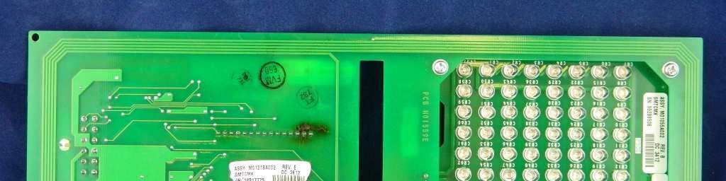
N6SLFSQR
Jun 23, 2015TRIND M01560 Module
Equipment Class
DCD - Part 15 Low Power Transmitter Below 1705 kHz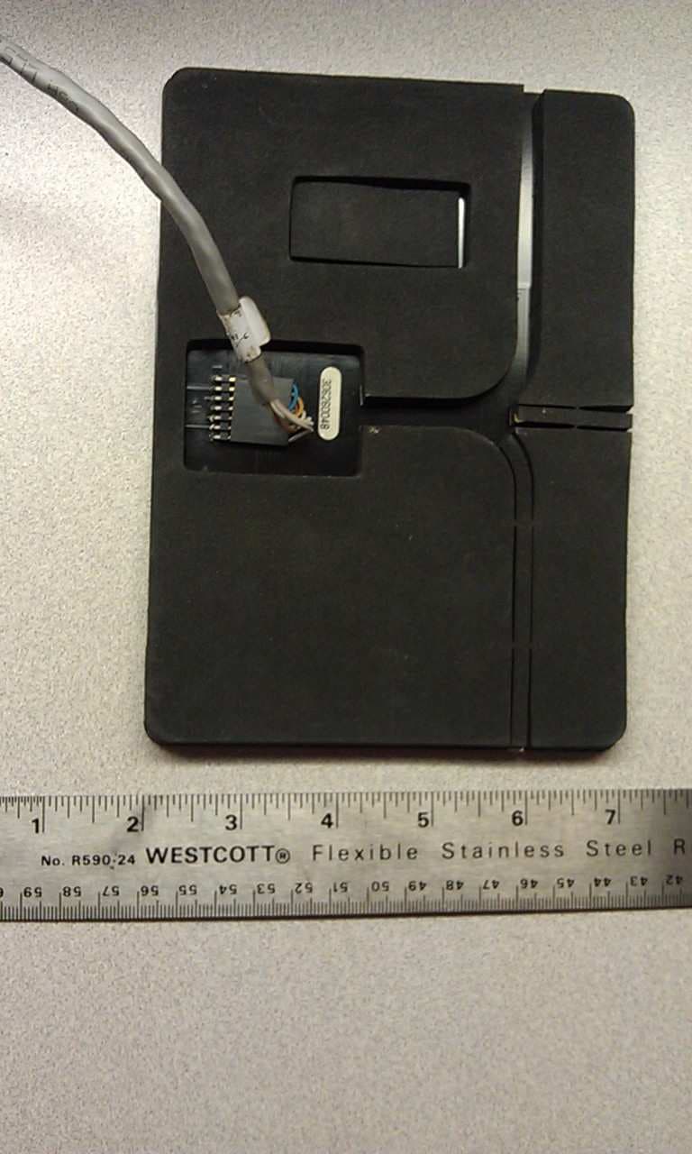
N6SLFMAT
Aug 12, 2013Mat Reader
Equipment Class
DCD - Part 15 Low Power Transmitter Below 1705 kHz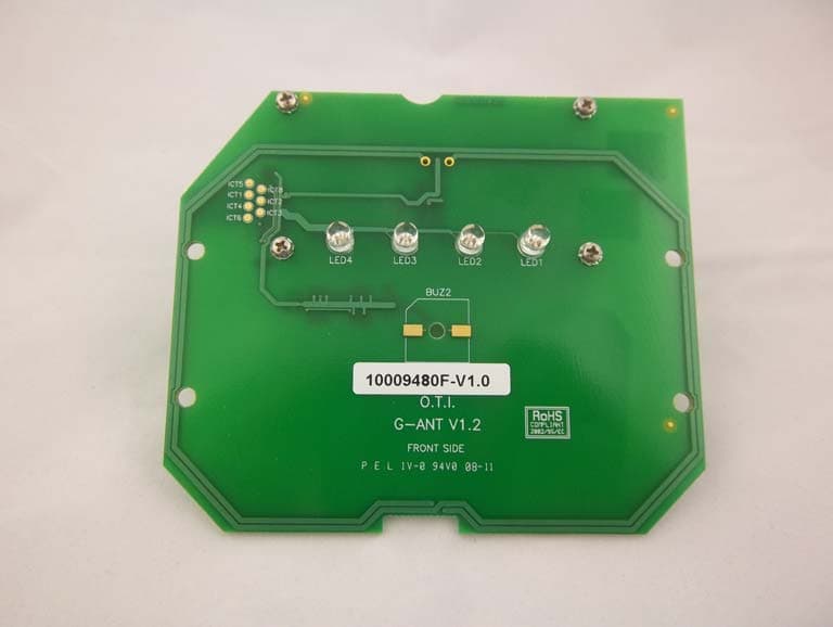
N6SGCM
May 24, 2011Contactless Smart Card Interface
Equipment Class
DXX - Part 15 Low Power Communication Device Transmitter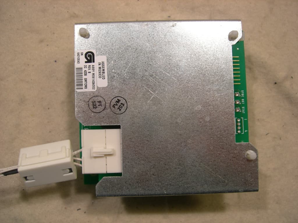
N6SLFTRIND
Jun 10, 2010TRIND RFID Module
Equipment Class
DCD - Part 15 Low Power Transmitter Below 1705 kHz
N6SGBIR15
Feb 01, 2006RFID Reader
Equipment Class
DXX - Part 15 Low Power Communication Device Transmitter