N6SGBIRARadio Frequency Identification Device
Gilbarco Inc.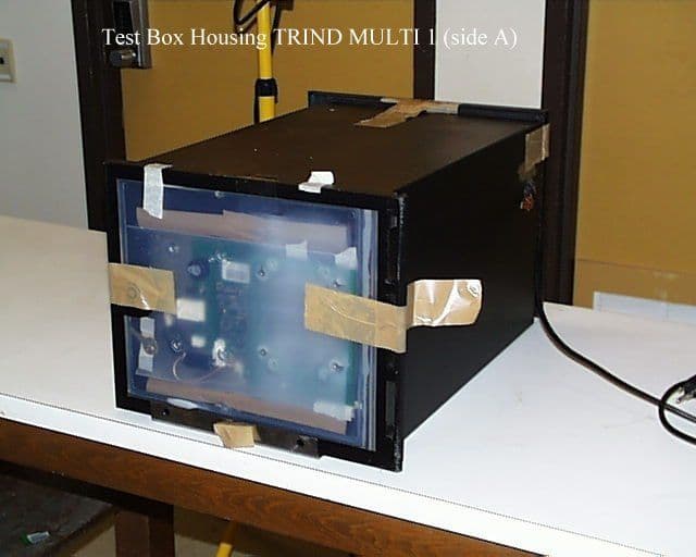
Click to zoom
Application Details
- Equipment Class
- DXX - Part 15 Low Power Communication Device Transmitter
- Date of Grant
- Jan 18, 2000
- Application Purpose
- Original Equipment
- Date of Application
- Oct 06, 1999
- Equipment Note
- Radio Frequency Identification Device
- Frequency Range
- 13.56000000 - 13.56000000
- Company
- Gilbarco Inc.
- Country
- United States
Documents & Files


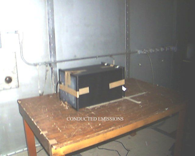
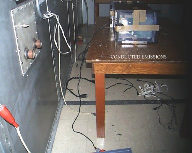
Document Text
Text extracted from the exhibit documents filed with the FCC. Open a document above to read the original.
Users Manual
MDE-3801 TRIND™ Multi 1 Transmitter/Receiver in Dispenser Retrofit Kit • 10/99Page 1 Introduction Purpose of this Manual This manual provides instruction for installing TRIND™ Multi 1 Retrofit Kits in The Advantage ® Series wide frame and narrow frame units with InfoScreen ® , monochrome CRIND ® , or single-line CRIND. The TRIND option allows customers to automatically authorize CRIND-equipped units using a hand-held transponder tag provided by a major oil company (MOC). Use this kit for one- or two-sided units. Prerequisites Before installing the TRIND kit, ensure that the existing CRIND has the Z-180 logic board T17764-XX, which is not provided in TRIND retrofit kit. Important Notice This equipment has been tested and found to comply with the limits for a Class A digital device pursuant to Part 15 of the FCC Rules. These limits are designed to provide reasonable protection against harmful interference when the equipment is operated in a commercial environment. This equipment generates, uses and can radiate radio frequency energy, and if not installed and used in accordance with the instruction manual, may cause harmful interference to radio communications. Operation of this equipment in a residential area is likely to cause harmful interference in which case the user will be required to correct the interference at his own expense. Changes or modifications not expressly approved by the manufacturer could void the user’s authority to operate this equipment. Required Reading Before installing the equipment, the installer must read, understand, and follow: •this manual • NFPA 30A, The Automotive and Marine Service Station Code • NFPA 70, The National Electric Code • applicable federal, state and local codes and regulations Failure to do so may adversely effect the safe use and operation of the equipment. Note: This kit must be installed by a Gilbarco ASC (Authorized Service Contractor) to insure warranty. Related Documents MDE-2531Pump & Dispenser Start-Up & Service Manual MDE-2562CRIND Service Manual MDE-2628Cash Acceptor Retrofit Assemblies for The Advantage Series with CRIND MDE-2620Graphics Panel Application for The Advantage Series PT-1728 The Advantage Series Illustrated Parts Manual PT-1736 CRIND Card Reader Illustrated Parts Manual MDE-3801 TRIND™ MULTI 1 Transmitter/Receiver in Dispenser Retrofit Kits C00012-001-XX Installation Introduction Page 2MDE-3801 TRIND™ Multi 1 Transmitter/Receiver in Dispenser Retrofit Kit • 10/99 Required Tools The following equipment is needed to install all TRIND™ Multi 1 kits • Allen wrench set, American standard • clean cloth or rag • chip extraction tool, e.g., IC extraction, Digikey Part No. K158-ND or equivalent • isopropyl alcohol (part# END-1082) • needle nose pliers • nut driver, 1/4'', 3/8'' • pocket knife • Q12534 CRIND diagnostic card • ratchet set, standard • screwdrivers, flat and Phillips head • static guard wrist strap The following additional tools are required if kit is to be installed on wide frame units with call or stop button on existing right options door. • center punch • deburring tool or round file • hand drill, battery electric or pneumatic • light hammer • pilot drill bit (between 3/32” and 1/4”) and 7/8” drill bit • standard tape measure or rule MDE-3801 TRIND™ Multi 1 Transmitter/Receiver in Dispenser Retrofit Kit • 10/99Page 3 Parts Lists Parts Lists Kits for Wide Frame Units, Dual- and Single-Sided Kits C00012-001-WF-D (dual-sided) and C00012-001-WF-S (single-sided) for The Advantage Wide Frames (48’’) contain the following parts. Note: Right Option Door Graphics T50148-G1 are an Order Entry Item. Q13781-01 Cable Group Cable group Q13781-01 for all kits contains the following cables: DescriptionPart NumberQuantity WF-D Kit Quantity WF-S Kit cable clamp, grayQ13558-041212 cable groupQ13781-01For components see table “Q13781-01 Cable Group” on page 3. cable tieQ10178-0288 card cage assembly T20538-G111 door assembly, right options clear with TRIND T20537-G121 graphics, right option doorT50148-G1(see note)(see note) grommet strip, solidQ10315-06.583 ft..583 ft. jump jackQ11011-011010 label plate, FCCN23936-0111 manual, graphics installation instructionsMDE-262011 manual, installation instructionsMDE-380111 nutQ12068-0422 software (firmware) CRIND ® BIOS K93744-0121 CablesPart NumberQuantity per kit Gateway to CRIND logicR20437-G011 AC powerR20580-G21 Light/Multi-protocol Reader, A-SideR20665-G11 Light/Multi-protocol Reader, B-SideR20665-G21 Gateway to Light/MPR/Power BoardsR20724-G11 Parts Lists Page 4MDE-3801 TRIND™ Multi 1 Transmitter/Receiver in Dispenser Retrofit Kit • 10/99 Kits for Narrow Frame Units, Dual- and Single-Sided Kits C00012-001-NF-D (dual-sided) and C00012-001-NF-S (single-sided) for The Advantage Narrow Frames (36’’) contain the following parts. Note: Right Option Door Graphics T50149-G1 are an Order Entry Item. DescriptionPart NumberQuantity WF-D Kit Quantity NF-S Kit cable clamp, grayQ13558-041212 cable groupQ13781-01For components see table “Q13781-01 Cable Group” on page 3. cable tieQ10178-0288 card cage assembly T20538-G111 door assembly, right options clear with TRIND T20539-G121 graphics, right option doorT50148-G1(see note)(see note) grommet strip, solidQ10315-06.583 ft..583 ft. jump jackQ11011-011010 label plate, FCCN23936-0111 manual, graphics installation instructionsMDE-262011 manual, installation instructionsMDE-380111 nutQ12068-0422 software (firmware) CRIND ® BIOS K93744-0121 MDE-3801 TRIND™ Multi 1 Transmitter/Receiver in Dispenser Retrofit Kit • 10/99Page 5 Safety Information Safety Information Alert Symbol and Signal Words Alert Symbol: This is a standard ANSI* approved alert symbol. When you see this symbol, be alert to the potential for a personal injury. * Reference American National Standard Bulletins ANSI Z535. Signal Words: These signal words alert you to important safety hazards. Safety Symbols: The following safety symbols are used throughout this manual to alert you to personal …
Text truncated - open the document above for the full version.
Cover Letter(s)
1 October 8, 1999 Gilbarco Inc 7300 West Friendly Avenue Post Office Box 22087 Greensboro, NC 27420-2087 Federal Communications Commission EQUIPMENT APPROVAL SERVICES P.O. Box 358315 Pittsburgh PA 15251-5315 Enclosed please find Form 159 along with a check for payment for the submittal of Gilbarco Inc.'s TRIND™ Multi 1 product. Both the check and paperwork list the Form 731 Confirmation Number and the FCC ID number. The check is in the amount of $1075.00 (Distributed as follows). $940.00 Devices under Parts 11, 15 &18 (except receivers) 731 & 159 EGC $135.00 Request for confidentiality 3/ 731 & 159 EBC *** Gilbarco Inc. is requesting and paying for confidentiality for schematics, internal photographs, block diagrams, and operational descriptions.*** Sincerely, Lester Ward Gilbarco Inc.
Test Report
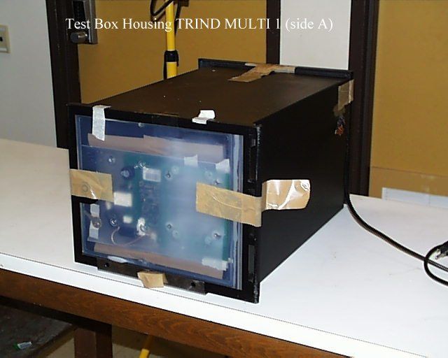
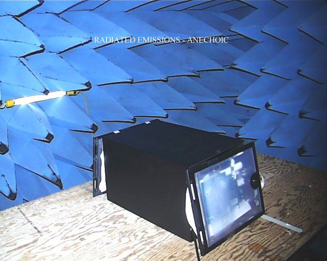
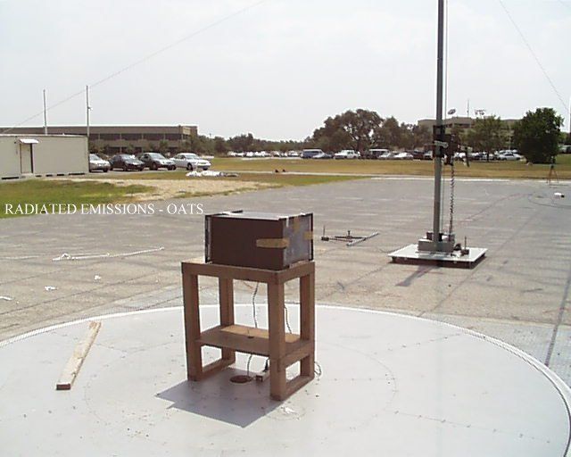
FCC ID: N6SGBIRA P:\10-3169\002fcc.doc Page 1 of 28 MEASUREMENT AND TECHNICAL REPORT ON THE GILBARCO TRIND™ MULTI 1 Southwest Research Institute 6220 Culebra Road San Antonio, Texas 78228-0510 Project 10-3169-002 Report Number EMCR 99/103 Prepared for: Gilbarco, Inc. 7300 West Friendly Avenue P.O. Box 22087 Greensboro, NC 27420-2087 Prepared by: David A. Carmony September 1999 Reviewed by:Approved by: _____________________________________________________________________________ Ismael Martinez, Jr.James J. Polonis Senior Engineering TechnologistManager Electromagnetic Compatibility Research SectionElectromagnetic Compatibility Research Section Communications Engineering DepartmentCommunications Engineering Department FCC ID: N6SGBIRA P:\10-3169\002fcc.doc Page 2 of 28 TABLE OF CONTENTS Page List of Tables ............................................................................................................................................... 3 1.0General Information ........................................................................................................................ 4 1.1Product Description......................................................................................................................... 4 1.2Related Grants................................................................................................................................. 4 1.3Tested System Details ..................................................................................................................... 4 1.4Test Methodology ........................................................................................................................... 5 1.5Test Facility..................................................................................................................................... 5 2.0Product Labeling ............................................................................................................................. 6 2.1FCC ID Label .................................................................................................................................. 6 2.2Location of Label on EUT .............................................................................................................. 6 2.3Label for the Exterior of Devices Incorporating the EUT .............................................................. 6 2.4Supplemental Information to be in the Reader Manual .................................................................. 6 3.0System Test Configuration.............................................................................................................. 7 3.1Justification ..................................................................................................................................... 7 3.2EUT Exercise ................................................................................................................................. 7 3.3Special Accessories......................................................................................................................... 7 3.4Equipment Modification ................................................................................................................. 7 3.5 Configuration of Tested System ..................................................................................................... 7 3.6Antenna System .............................................................................................................................. 7 4.0Block Diagram of the TRIND™ MULTI 1 ..................................................................................... 8 5.0Conducted and Radiated Measurement Photos..................................................................... ........ 9 6.0Conducted Emission Data ............................................................................................................. 10 6.1Conducted Measurement Data ...................................................................................................... 10 6.2Conducted Test Instrumentation ................................................................................................... 10 7.0Radiated Emission Data ................................................................................................................ 11 7.1Radiated Measurement Data ......................................................................................................... 11 7.2Test Instrumentation for Radiated Measurements ........................................................................ 15 7.3Field Strength Calculation ............................................................................................................ 15 Appendix A: Conducted Measurement Plots ............................................................................................. 16 Appendix B: Radiated Signature Measurement Plots................................................................................ 19 Appendix C: Test Instrumentation ............................................................................................................. 25 Appendix D: Photos of Tested EUT .......................................................................................................... 27 Appendix E: Photos of Test Setups............................................................................................................ 28 Attachment 1: Functional Description and Block Diagram Attachment 2: Installation Instructions Attachment 3: FCC ID Label Attachment 4: Schematics FCC ID: N6SGBIRA P:\10-3169\002fcc.doc Page 3 of 28 LIST OF TABLES TablePage 1.1System Components ......................................................................................................................... 4 6.1Worst Case Conducted Emission Levels ....................................................................................... 10 7.1Measurements of Fundamental Freq…
Text truncated - open the document above for the full version.
Contact Information
Applicant
Bob Sykes(EMC Engineer)
Technical Contact
Gilbarco, Inc.Lester Ward
[email protected]336-547-5559
7300 West Friendly Avenue · Greensboro, North Carolina · United States
Non-Technical Contact
Gilbarco, Inc.Lester Ward
[email protected]336-547-5559
Test Firm
Southwest Research InstituteDavid Carmony
210-684-5111
Technical Specifications
| # | Rule Parts | Frequency Range | Power Output |
|---|---|---|---|
| 1 | 15C | 13.56 MHz - 13.56 MHz | - |
Other Applications from Gilbarco Inc.
N6SLFSQR
Jun 23, 2015TRIND M01560 Module
Equipment Class
DCD - Part 15 Low Power Transmitter Below 1705 kHz
N6SLFMAT
Aug 12, 2013Mat Reader
Equipment Class
DCD - Part 15 Low Power Transmitter Below 1705 kHz
N6SLFECIM
Mar 26, 2013RFID Module
Equipment Class
DCD - Part 15 Low Power Transmitter Below 1705 kHz
N6SGCM
May 24, 2011Contactless Smart Card Interface
Equipment Class
DXX - Part 15 Low Power Communication Device Transmitter
N6SLFTRIND
Jun 10, 2010TRIND RFID Module
Equipment Class
DCD - Part 15 Low Power Transmitter Below 1705 kHz