N6SMRIR11Point of Sale Mat Reader System
Gilbarco Inc.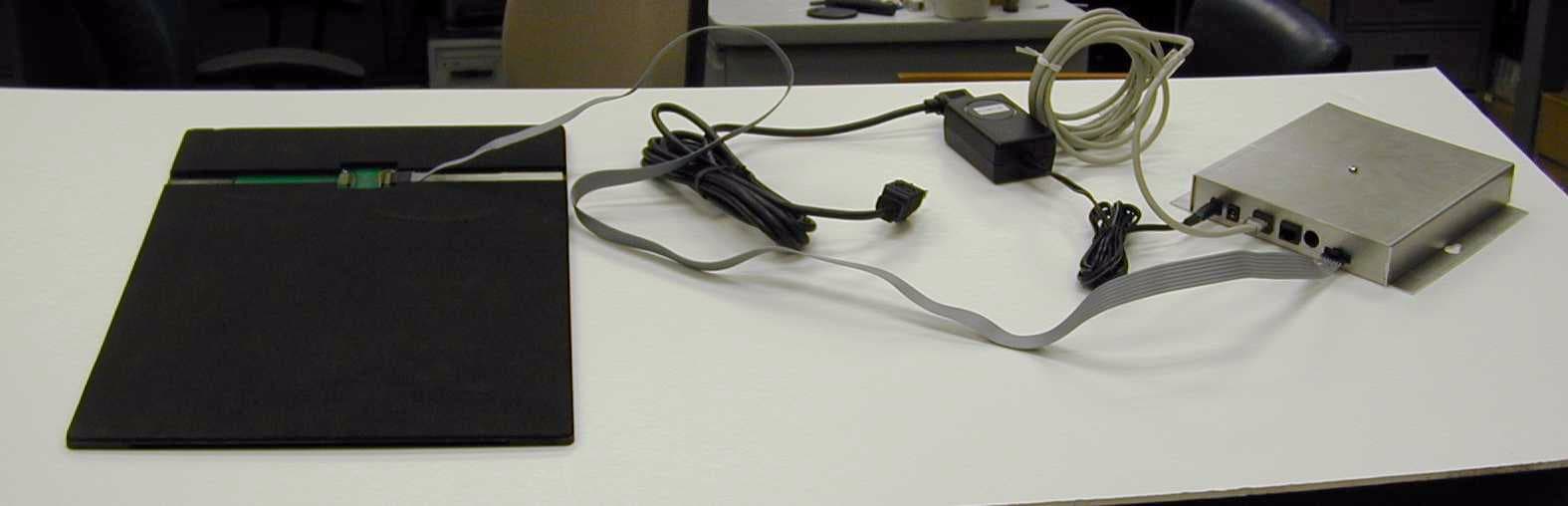
Click to zoom
Application Details
- Equipment Class
- DXX - Part 15 Low Power Communication Device Transmitter
- Date of Grant
- Jun 06, 2001
- Application Purpose
- Original Equipment
- Date of Application
- Jun 06, 2001
- Equipment Note
- Point of Sale Mat Reader System
- Frequency Range
- 0.13400000 - 0.13400000
- Company
- Gilbarco Inc.
- Country
- United States
Documents & Files
Document Text
Text extracted from the exhibit documents filed with the FCC. Open a document above to read the original.
Users Manual
MDE-4017 TIRIS™ Transmitter/Receiver Mat Reader Assembly Kit C00016-XXX Installation • May 2001Page 1 P r eli m i na ry 05/ 24/ 01 Introduction Purpose of this Manual This manual provides instruction for installing TIRIS™ Mat Reader Assembly Kit C00016- XXX. The TIRIS™ option allows customers to automatically authorize non-cash sales using a hand- held transponder tag. Important Notice This equipment has been tested and found to comply with the limits for a Class A digital device pursuant to Part 15 of the FCC Rules. These limits are designed to provide reasonable protection against harmful interference when the equipment is operated in a commercial environment. This equipment generates, uses and can radiate radio frequency energy, and if not installed and used in accordance with the instruction manual, may cause harmful interference to radio communications. Operation of this equipment in a residential area is likely to cause harmful interference in which case the user will be required to correct the interference at his own expense. Changes or modifications not expressly approved by the manufacturer could void the user’s authority to operate this equipment. The long term characteristics or the possible physiological effects of radio frequency electromagnetic fields have not been investigated by Underwriters’ Laboratories, Inc. (UL ® ). Required Reading Before installing the equipment, the installer must read, understand, and follow: •this manual •NFPA 70, The National Electric Code •applicable federal, state and local codes and regulations Failure to do so may adversely effect the safe use and operation of the equipment. MDE-4017 TIRIS™ Transmitter/Receiver Mat Reader Assembly Kit C00016-XXX Installation May 2001 Page 2MDE-4017 TIRIS™ Transmitter/Receiver Mat Reader Assembly Kit C00016-XXX Installation • May 2001 P r e liminary 05/ 2 4/01 Related Documents Installer must obtain, read and understand all site preparation documentation provided by the point of sale company authorizing the installation before attempting to install this equipment. In addition, the installer must be familiar with the information in the following documents. Required Tools The following equipment is needed to install all TIRIS™ mat reader kits: •drill motor and bits •needle nose pliers •screwdriver, Phillips ® head •Zircon ® stud/bracket finder Parts Lists C00016-006 Kits contain the following parts: The following components are also required. Document NumberTitleGOLD Library MDE-3110PC-Based G-SITE System Installation ManualG-SITE MDE-3111PC-Based G-SITE System Start-Up and Service Manual• G-SITE • Service Manual MDE-3620Gilbarco POS Console Site Preparation ManualSite Prep DescriptionPart NumberQuantity box, interface assemblyM01814A0011 tape, neoprene foamM01870B0012 channel, plastic fillerM01871B0011 cable, mat reader driveM01872A0011 tape, acrylic foamK85492-721 power supplyM01878B0011 jack, jump, push-to-startQ11011-011 cable, data, CAT-5Q13482-061 clamp, cable, stick on, smallQ13459-013 document, installation (this document)MDE-40171 diagram, block and/or interconnectM018730 DescriptionPart NumberQuantity graphicsMR01002G0031 reader, mat, TIRIS device Note: The Mat Reader is delivered with the graphics in place. M01787B0011 Page 3MDE-4017 TIRIS™ Transmitter/Receiver Mat Reader Assembly Kit C00016-XXX Installation • May 2001 Preliminary 0 5/ 24/0 1 Important Safety Information This section introduces the hazards and safety precautions associated with installing, inspecting, maintaining or servicing this product. Before performing any task on this product, read this safety information and the applicable sections in this manual, where additional hazards and safety precautions for your task will be found. Electrical shock could occur and cause death or serious injury if these safe service procedures are not followed. Preliminary Precautions Read, understand and follow this manual and any other labels or related materials supplied with this equipment. Follow the Regulations There is applicable information in: NFPA 70: National Electrical Code (NEC); OSHA regulations; and federal, state, and local codes which must be followed. Failure to install, maintain or service this equipment in accordance with these codes, regulations and standards may lead to legal citations with penalties or affect the safe use and operation of the equipment. Page 4MDE-4017 TIRIS™ Transmitter/Receiver Mat Reader Assembly Kit C00016-XXX Installation • May 2001 P r e liminary 05/ 2 4/01 Safety Symbols and Warning Words Alert Symbol This safety alert symbol is used in this manual and on warning labels to alert you to a precaution which must be followed to prevent potential personal safety hazards. Obey safety directives that follow this symbol to avoid possible injury or death. Signal Words These signal words used in this manual and on warning labels tell you the seriousness of particular safety hazards. The precautions that follow must be followed to prevent death, injury or damage to the equipment. Proper Grounding is Required Proper grounding is required for safe operation. See installation manual and applicable NEC, NFPA and local electrical codes for requirements. Avoid Pinched Wires Pinched or cut wires (cables) may damage components. Exposed wires could create sparks and electrical shorts when applying power. Other Useful Safety Information Replacement Parts Use only genuine Marconi replacement parts. Using parts other than genuine Marconi replacement parts could create a safety hazard, violate national, state and local regulations or void warranty. This signal word designates a hazard or unsafe practice which may result in minor injury. This signal word is used to alert you to a hazard or unsafe practice which will result in death or serious injury. This alerts you to a hazard or unsafe practice that could result in death or serious injury. CAUTION When used by itself, CAUTION designates a hazard or unsafe practice which may result…
Text truncated - open the document above for the full version.
Attestation Statements
Marconi Commerce Systems Inc. 7300 W. Friendly Avenue P. O. Box 22087 Greensboro, NC 27420-2087 USA Telephone: 336 547 5000 Fax: 336 292 8871 Telex: 4949970 Web site: www.marconicommerce.com Manufacturer’s Letter Date 5/9/2001 American Telecommunications Certification Body, Inc. 6731 Whittier Avenue Suite C110 McLean, VA 22101 RE: Certification Application FCC ID:N6SMRIR11 To Whom It May Concern: Please be advised that the manufacturer will ensure that the above-referenced model will be manufactured in accordance with the FCC Rules and Regulations. Thank you for your attention to this matter. Sincerely, Lester Ward (Manager of Reliability Engineering)
Attestation Statements
Marconi Commerce Systems Inc. 7300 W. Friendly Avenue P. O. Box 22087 Greensboro, NC 27420-2087 USA Telephone: 336 547 5000 Fax: 336 292 8871 Telex: 4949970 Web site: www.marconicommerce.com Federal Communications Commission 4/25/2001 445 Twelfth St., S.W. Washington, D.C. 20554 To Whom It May Concern: Since recently questions regarding operation in restricted bands have received a great deal of scrutiny, this to specifically point out claims that the N6SMRIR11 device does not violate restricted bands. The measurement report specifically states that the 90-110 kHz restricted band was investigated “Scans were performed starting at 110 kHz to verify that the fundamental emission was not in the 90-110 kHz restricted band.” This confirmed that the fundamental 134 kHz is not in the restricted band 90-110 kHz. Regarding the tag emissions, they are very small. The tag emissions are included in the measurements made in the restricted band 90-110 kHz as referenced in the paragraph above because a tag is needed to fully exercise the N6SMRIR11device. For added assurance that the main lobes of the tag signals do not enter the restricted band, the tag data frequencies and their corresponding pulse widths are provided below. DataTransmit Frequency (kHz)Pulse Width micro-sec Low Bit134.2119.9 High Bit123.2129.2 Sincerely, Lester Ward (Manager of Reliability Engineering)
Block Diagram
FCC ID: N6SMRIR11 Figure 1: Marconi TIRIS™Mat Reader Radio Frequency Identification (RFID) Functional Block Diagr am Q13698-01 UL 1950 Approved Plug In Power Supply 115VAC to 12VDC@1A Marconi TIRIS™ Indoor MicroReader Board T20656 Assembly JDC1 JDC2 J1IN J2OUT P3 +12VDC 115VAC to other RFID Optional device (sync) RS-232 Shutter/Beeper Control and 134.2kHz RF Signal LCD Shutter/ Beeper/Antenna Assembly (T20645) M01434A001 RS-232 +12VDC Point of Sale Controller RI-STU-MRD1 Micro-Reader (134kHz Intentional Radiator) Antenna Cable M01872B001 M01803 (PCB)
Cover Letter(s)
Marconi Commerce Systems Inc. 7300 W. Friendly Avenue P. O. Box 22087 Greensboro, NC 27420-2087 USA Telephone: 336 547 5000 Fax: 336 292 8871 Telex: 4949970 Web site: www.marconicommerce.com Letter Of Agency Date 5/9/2001 American Telecommunications Certification Body, Inc. 6731 Whittier Avenue Suite C110 McLean, VA 22101 To Whom It May Concern: Please be advised that Marconi Commerce Systems authorizes American Telecommunications Certification Body, Inc.to act on our behalf, until otherwise notified, for applications submitted to American Telecommunications Certification Body, Inc. (ATCB). We certify that we are not subject to denial of federal benefits, that includes FCC benefits, pursuant to Section 5301 of the Anti-Drug Abuse ACT of 1988, U.S.C. 862. Further, no party, as defined in 47 CFR 1.2002(b), to the application is subject to denial of federal benefits, that includes FCC benefits. Thank you for your attention to this matter. Specifically N6SMRIR11 (134 kHz Intentional Radiator – Mat Reader) Sincerely, Lester Ward (Manager of Reliability Engineering)
Cover Letter(s)
Marconi Commerce Systems Inc. 7300 W. Friendly Avenue P. O. Box 22087 Greensboro, NC 27420-2087 USA Telephone: 336 547 5000 Fax: 336 292 8871 Telex: 4949970 Web site: www.marconicommerce.com Request for Confidentiality Date 4/27/2001 American Telecommunications Certification Body, Inc. 6731 Whittier Avenue Suite C110 McLean, VA 22101 RE: Certification Application FCC ID:N6SMRIR11 To Whom It May Concern: In reference to FCC ID N6SMRIR11, Marconi Commerce Systems is requesting confidentiality for schematic diagrams. Marconi Commerce Systems posted file: TRIND Mat Reader Electrical Schematics N6SMRIR11.pdf Texas Instruments posted files on behalf of Marconi Commerce Systems as follows: • Electrical schematics of MicroReader RI-STU-MRD1 *** When their confidential files are posted, Texas Instruments will submit a more detailed letter of confidentiality for the documents that they wish to have kept confidential *** This request is being made under the provisions of Section 0.457(d) of the Commission’s rules, and Section 552(b)(4) of the Freedom of Information Act. These schematic diagrams are proprietary and not customarily released to the public. As a matter of fact, those schematics involving the Texas Instruments series 5000 components were posted directly by TI (even Marconi Commerce Systems is not privileged to view them). These schematic diagrams should fall within the scope of Section 552(b)(4) as trade secrets, Under the provisions of Section 0.457(d), these schematic diagrams should not be routinely available for public inspection. The application contains technical information which Marconi Commerce Systems deems to be trade secrets and proprietary. If made public, the information might be used to the disadvantage of the applicant in the market place. Thank you for your attention to this matter. Sincerely, Lester Ward (Manager of Reliability Engineering)
External Photos
Marconi Commerce Systems N6SMRIR11 Mat Reader External Photos Page 1 of 4 N6SMRIR11 Marconi Commerce Systems - Mat Reader (Overall View - Mat is flipped over to show the connections ) Page 2 of 4 N6SMRIR11 Marconi Commerce Systems - Mat Reader (BackView - shows ribbon cable connection) Page 3 of 4 N6SMRIR11 Marconi Commerce Systems - Mat Reader (Front View of Mat) Page 4 of 4
ID Label/Location Info
M01814A001 Interface Box M01868B001 Label 50.0 mm X152.4mm N6SMRIR11 Mat Reader label contents and location Marconi Commerce Systems Canada XXXXXXXXX
Operational Description
Functional Description 1.0 Overview of Product Operation The use of the Mat Reader device may be illustrated through an example application. A customer enters a fast serve restaurant and places an order. Typically, the customer would present a handheld transponder to the Mat Reader that would be on the counter top. The 134 kHz signal from the Reader “illuminates” the transponder. The transponder then transmits the Customer’s ID. If added security is needed, the Reader makes a challenge (transmission to the transponder) which forces the transponder to transmit additional information to prove that the transponder is legitimate. The Reader subsequently passes the Customer ID to a Point of Sale Controller via an RS232 port where the customer billing takes place. The 134 kHz signal originates in the Micro-Reader (Texas Instruments part number RI-STU-MRD1) which is on the T20656 Assembly. Subsequently, this signal travels over the antenna cable (M01872B001) to the antenna (M01434A001) where it is radiated. The customer transponder replies at 134 kHz with the customer ID once it is energized by the Reader and the proper protocol between the Reader and the transponder is established. The same antenna that transmitted the reader signal receives the transponder reply. The transponder’s reply signal is routed from the antenna to the Micro-Reader (RI- STU-MRD1) and then to the T20656 Assembly where the signal is interpreted to determine the customer ID. The customer ID is then relayed via RS232 to a Point of Sale Controller for customer billing. Page 1 of 4 Product Description Marconi Commerce Systems Inc.'s product (for which this submittal is being filed) allows customers wishing to purchase products to interface directly with a Point-Of-Sale via a handheld transponder. The product is called Marconi TIRIS™ Mat Reader (TIRIS: Texas Instruments Registration and Identification System). The Marconi TIRIS™ Mat Reader transmits at 134.2kHz, which provides energy to the handheld tag. The handheld tags contain a unique and secure ID code so each customer can be identified by their individually registered tag. The low frequency antennas of the system create magnetic charge-up fields, known as "read-zones". As soon as a tag enters the "read-zone" (the magnetic charge-up field created by the antenna) the reader receives the unique ID code. The Marconi TIRIS™ Mat Reader (Part # C00016-XXX) is a Radio Frequency Identification Device (RFID) which is designed for use in conjunction with handheld battery-less transponders (Texas Instruments Part # RI-TRP-Series). The user carries the handheld transponder. The transmitter portion of the Marconi TIRIS™ Mat Reader operates at 134.2kHz and is subject to FCC Part 15, Subpart C, "Intentional Radiator"; paragraphs 15.207 and 15.209. The digital electronics portion of the Marconi TIRIS™ Mat Reader is subject to FCC Part 15, Subpart B, "Unintentional Radiator", paragraph 15.109, under the Class A limits and as such, the TRIND™TIRIS™EG™ is incorporated into an application that is subject to Class A limits. Tested System Details The Marconi TIRIS™ Mat Reader System is mounted into an application such as a POS terminal counter or other similar industrial applications. The system includes one Indoor Gateway/MicroReader Board (M01803), one mat reader assembly (M01787B001), which includes one 134.2kHz low 'Q' printed circuit board antenna (T20645) and one LCD shutter. The system also includes a 120 VAC to +12VDC LPS Wall Mounted Transformer for input power. These components are listed in Table 1.1, and the functional relationship is provided in Figure 1: Marconi TIRIS™ Mat Reader RFID Functional Block Diagram. The 134.2 kHz transmit signal originates on the MicroReader located on the Indoor MicroReader Board and travels via its' respective cable to its' respective antenna where it is intentionally radiated. These components are assembled per the drawings in the EMC Components and Electrical Schematics file. The Marconi TIRIS™ Mat Reader operates from 120VAC converted to +12VDC using a step- down transformer. The +12VDC is then converted to +26VDC and +5VDC by means of switching power supply circuits located on the Indoor Gateway/MicroReader Board. The system functional block diagram is located at the end of this file. Page 2 of 4 Circuit Board Descriptions • The Indoor MicroReader Board Assembly (M01803) has digital interface and RS-232 conversion circuitry, a +12VDC to +26VDC boost switcher, a +12VDC to +5VDC buck switcher, and LCD drive circuitry. The Gateway interface portion of this board manages RFID processing and provides simple, generic event messages to the POS electronics via RS-232. The MicroReader is also located on this board and is the origination point of the intentionally radiated 134.2kHz LF signal. • The MicroReader, (Texas Instruments part number RI-STU-MRD1), is soldered on the Gateway/Indoor MicroReader Board Assembly. It has a serial communications interface (SCI), which supports RS-232 protocol communication and TTL data communication. It provides radio frequency (RF) 134 kHz control functions to read and program TIRIS™ transponders. • The Marconi TIRIS™ Mat Reader (T20645) antenna is a 47 μ H, low 'Q' (10-20) antenna that works with the MicroReader. It is energized by the MicroReader at 132kHz to generate the exciter frequency of 134.2kHz. Because of its’ low 'Q', it does not need to be tuned any further in this application. Table 1. 1 TESTED LF SYSTEM COMPONENTS Component DescriptionMarconi Part Number Texas Instruments Part Number Indoor MicroReader Board Assembly (1) M01803NA MicroReader (1) (one per M01803) Q13551-01RI-STU-MRD1 Marconi Mat Reader Antenna T20645NA +12VDC Wall Mounted Power Supply M01878B001NA Page 3of 4 Page 4of 4 FCC ID: N6SMRIR11 Figure 1: Marconi TIRIS™Mat Reader Radio Frequency Identification (RFID) Functional Block Diagr am Q13698-01 UL 1950 Approved Plug In Power Supply 115VAC to 12VDC@1A Marconi TIRIS™ Indoor MicroReader Board …
Text truncated - open the document above for the full version.
Parts List/Tune Up Info
Parts Lists C00016-006 Kits contain the following parts: The following components are also required. Description Part Number Quantity box, interface assembly M01814A001 1 tape, neoprene foam M01870B001 2 channel, plastic filler M01871B001 1 cable, mat reader drive M01872A001 1 tape, acrylic foam K85492-72 1 power supply M01878B001 1 jack, jump Q11011-01 1 cable, data, CAT5 Q13482-06 1 clamp, cable, stick on, small Q13459-01 3 document, installation (this document) MDE-4017 1 diagram, block and/or interconnect M01873 0 Description Part Number Quantity graphics MR01002G003 1 graphics MR01002GR003 0 reader, mat M01787B001
Test Report
FCC ID: N6SMRIR11 P:\10-04567.01.001\rpt32.doc 1 of 28 MEASUREMENT AND TECHNICAL REPORT ON THE MARCONI COMMERCE SYSTEMS TIRIS™ MAT READER RADIO FREQUENCY IDENTIFICATION DEVICE Southwest Research Institute 6220 Culebra Road San Antonio, Texas 78228-0510 Project 10.04567.01.001 Report Number EMCR 01/032 Prepared for: Marconi Commerce Systems 7300 West Friendly Avenue P.O. Box 22087 Greensboro, NC 27420-2087 Prepared by: David A. Carmony June 2001 Reviewed by:Approved by: Ismael Martinez, Jr.James J. Polonis Sr. Engineering TechnologistManager Electromagnetic Compatibility Research SectionElectromagnetic Compatibility Research Section Communications Engineering DepartmentCommunications Engineering Department FCC ID: N6SMRIR11 P:\10-04567.01.001\rpt32.doc 2 of 28 TABLE OF CONTENTS Page List of Tables................................................................................................................................................ 3 1.0General Information ........................................................................................................................ 4 1.1Product Description......................................................................................................................... 4 1.2Related Grants................................................................................................................................. 4 1.3Tested System Details ..................................................................................................................... 4 1.4Test Methodology ........................................................................................................................... 5 1.5Test Facility..................................................................................................................................... 5 2.0Product Labeling............................................................................................................................. 6 2.1FCC ID Label.................................................................................................................................. 6 2.2Location of Label on EUT............................................................................................................... 6 2.3Supplemental Information to be in the Reader Manual.................................................................... 6 3.0System Test Configuration.............................................................................................................. 7 3.1Justification ..................................................................................................................................... 7 3.2EUT Exercise ................................................................................................................................ 7 3.3Special Accessories......................................................................................................................... 7 3.4Equipment Modification ................................................................................................................. 7 3.5 Configuration of Tested System...................................................................................................... 7 4.0Block Diagram of the TIRIS™ Mat Reader System ........................................................................ 8 5.0Conducted and Radiated Measurement Photos ............................................................................... 9 6.0Conducted Emission Data............................................................................................................. 10 6.1Conducted Measurement Data ...................................................................................................... 10 6.2Conducted Test Instrumentation ................................................................................................... 10 7.0Radiated Emission Data ................................................................................................................ 11 7.1Radiated Measurement Data ......................................................................................................... 11 7.2Test Instrumentation for Radiated Measurements......................................................................... 12 7.3Field Strength Calculation............................................................................................................. 12 Appendix A: Conducted Measurement Plots ............................................................................................. 13 Appendix B: Radiated Signature Scan Plots and OATS Data Sheets ......................................................... 16 Appendix C: Test Instrumentation ............................................................................................................. 25 Appendix D: Photos of Tested EUT............................................................................................................ 27 Appendix E: Photos of Test Setups............................................................................................................ 28 Attachment 1: Functional Description and Block Diagram Attachment 2: Installation Instructions Attachment 3: FCC ID Label Attachment 4: Schematics FCC ID: N6SMRIR11 P:\10-04567.01.001\rpt32.doc 3 of 28 LIST OF TABLES TablePage 1.1 TIRIS™ Mat Reader Components ................................................................................................... 4 6.1 Worst Case Conducted Emission Levels........................................................................................ 10 7.1 Measurement of Fundamental Frequency ......................................................................................11 7.2 Measurement of Spurious Emissions ............................................................................................. 11 FCC ID: N6SMRIR11 P:\10-04567.01.001\rpt32.doc 4 of 28 1.0 GENERAL …
Text truncated - open the document above for the full version.
Test Setup Photos
Radiated Emissions Pre-scan (Anechoic) Test Setup Radiated Emissions OATS Test Setup (110 kHz to 30 MHz) Radiated Emissions OATS Test Setup (30 MHz to 1 GHz) Conducted Emissions Test Setup
Contact Information
Applicant
Bob Sykes(EMC Engineer)
Technical Contact
Marconi Commerce SystemsLester G Ward
[email protected]336 547 5559
7300 West Friendly Avenue · Greensboro, North Carolina · United States
Test Firm
Southwest Research InstituteDavid Carmony
210-684-5111
Technical Specifications
| # | Rule Parts | Frequency Range | Power Output |
|---|---|---|---|
| 1 | 15C | 0.134 MHz - 0.134 MHz | - |
Other Applications from Gilbarco Inc.
N6SLFSQR
Jun 23, 2015TRIND M01560 Module
Equipment Class
DCD - Part 15 Low Power Transmitter Below 1705 kHz
N6SLFMAT
Aug 12, 2013Mat Reader
Equipment Class
DCD - Part 15 Low Power Transmitter Below 1705 kHz
N6SLFECIM
Mar 26, 2013RFID Module
Equipment Class
DCD - Part 15 Low Power Transmitter Below 1705 kHz
N6SGCM
May 24, 2011Contactless Smart Card Interface
Equipment Class
DXX - Part 15 Low Power Communication Device Transmitter
N6SLFTRIND
Jun 10, 2010TRIND RFID Module
Equipment Class
DCD - Part 15 Low Power Transmitter Below 1705 kHz