N6SMRIR2Radio Frequency Identification device
Gilbarco Inc.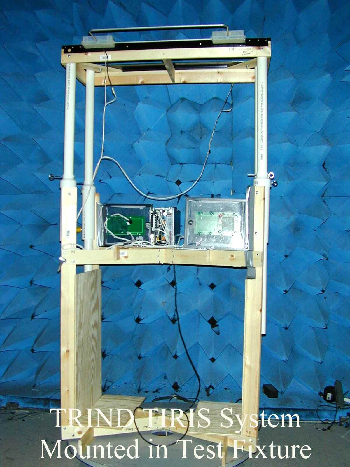
Click to zoom
Application Details
- Equipment Class
- DCD - Part 15 Low Power Transmitter Below 1705 kHz
- Date of Grant
- Jun 05, 2000
- Application Purpose
- Original Equipment
- Date of Application
- Apr 26, 2000
- Equipment Note
- Radio Frequency Identification device
- Frequency Range
- 0.13420000 - 0.13420000
- Company
- Gilbarco Inc.
- Country
- United States
Documents & Files





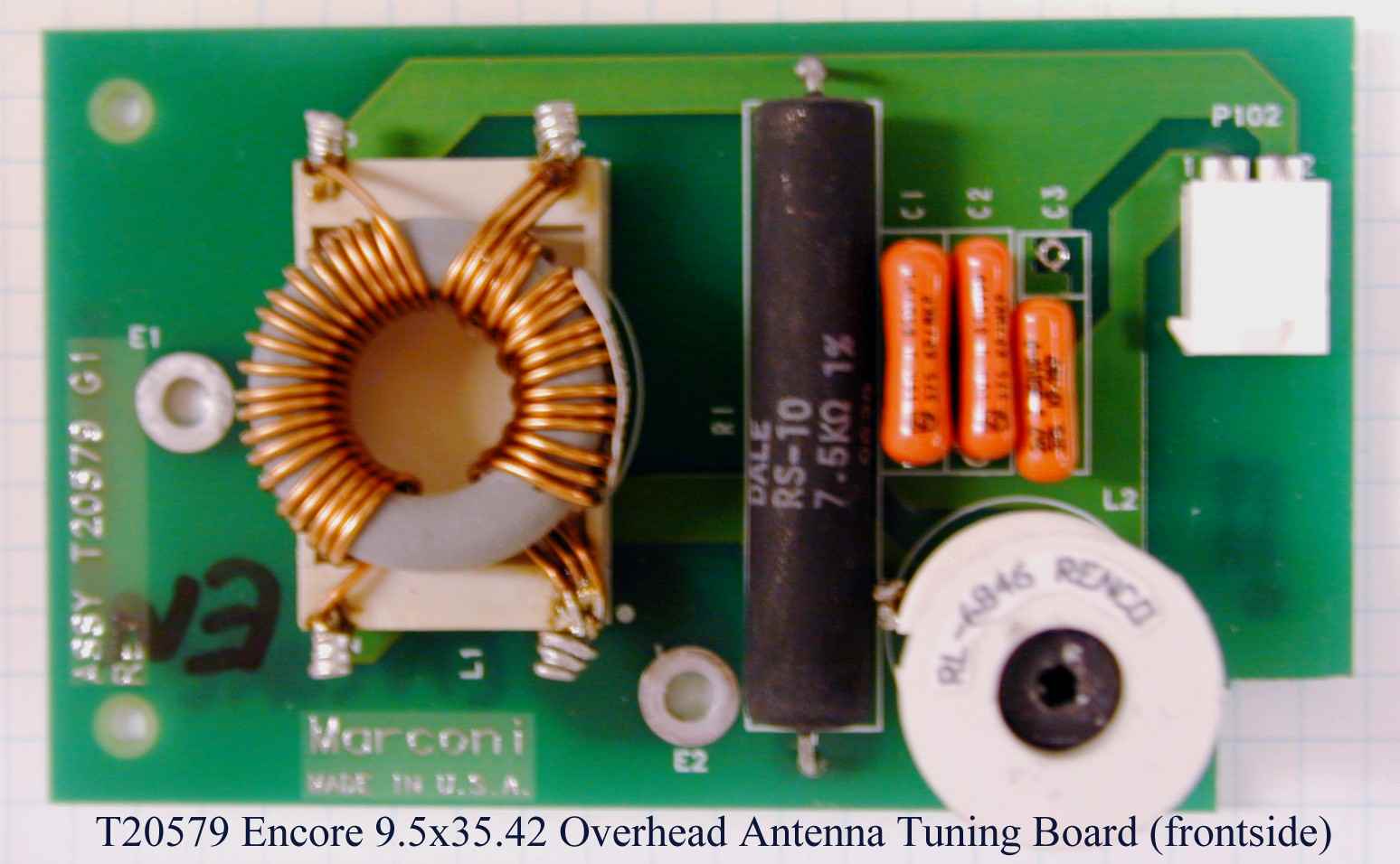
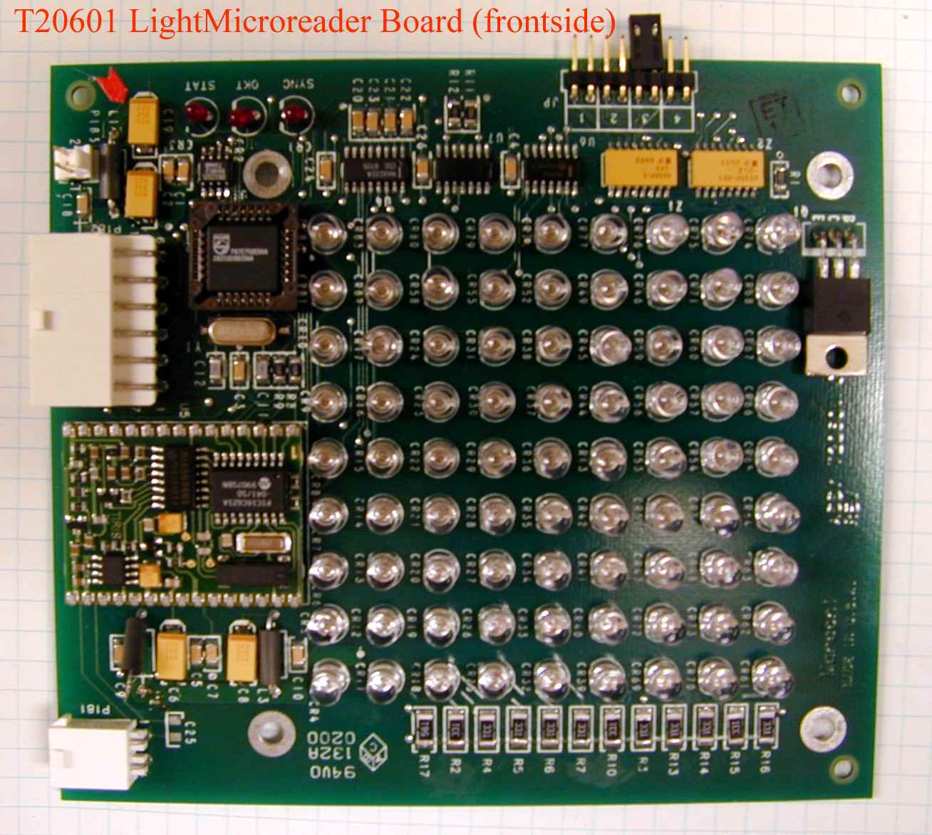
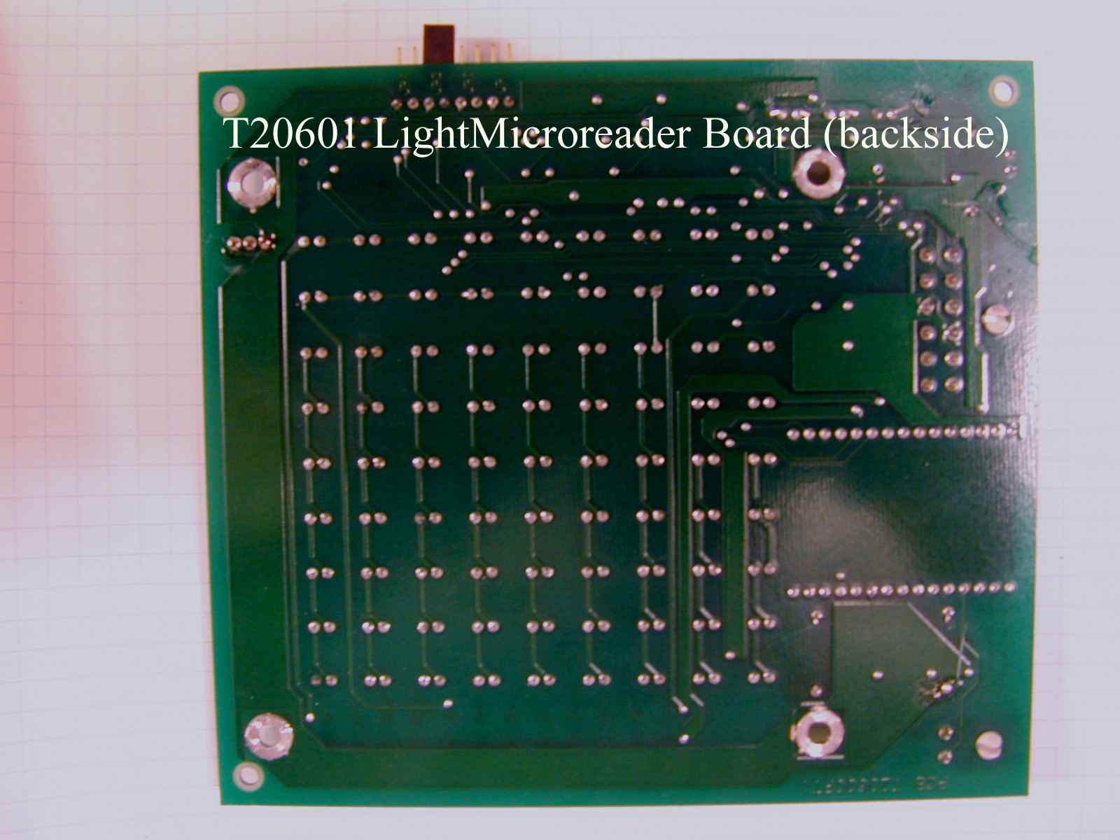
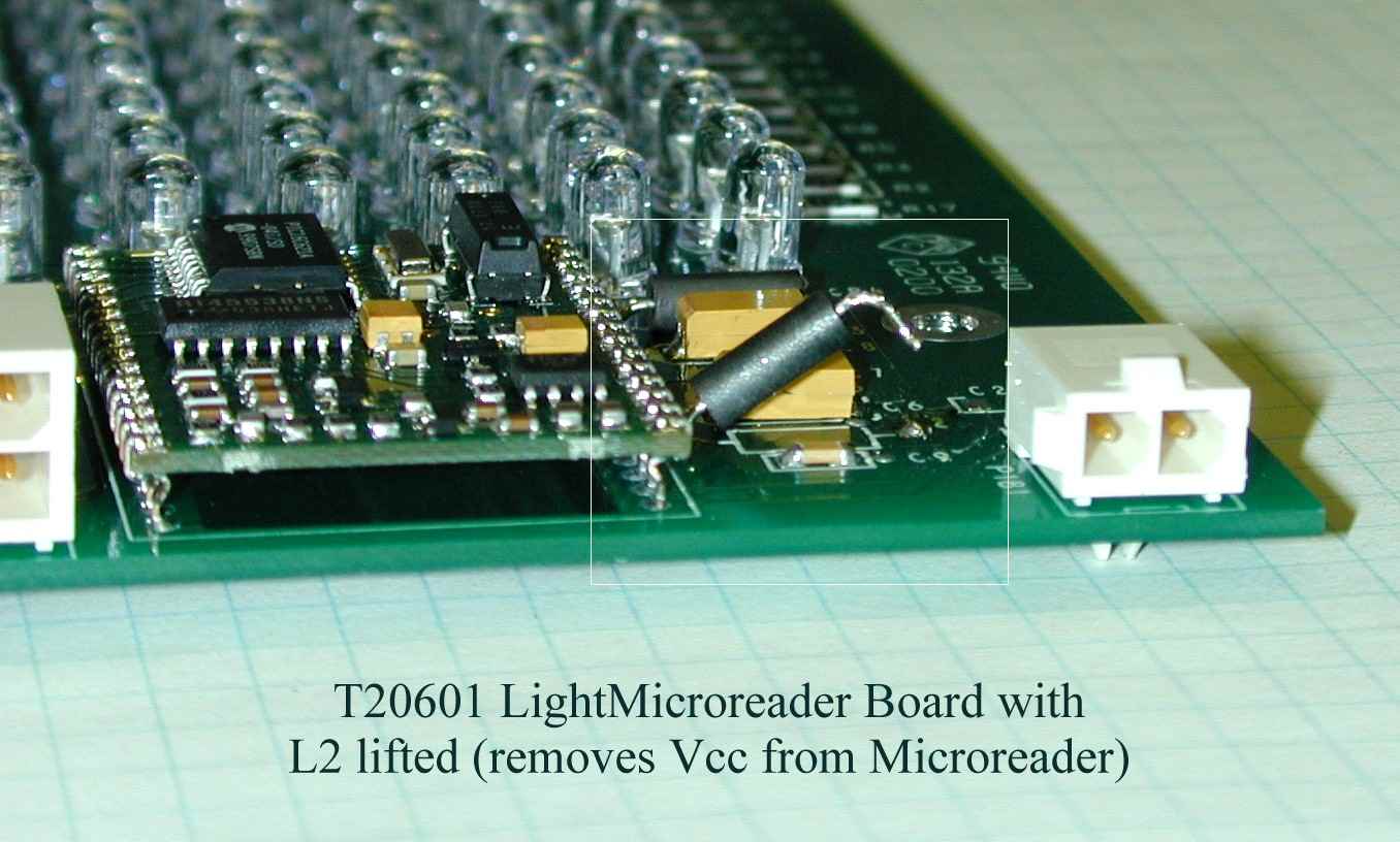






Document Text
Text extracted from the exhibit documents filed with the FCC. Open a document above to read the original.
Users Manual
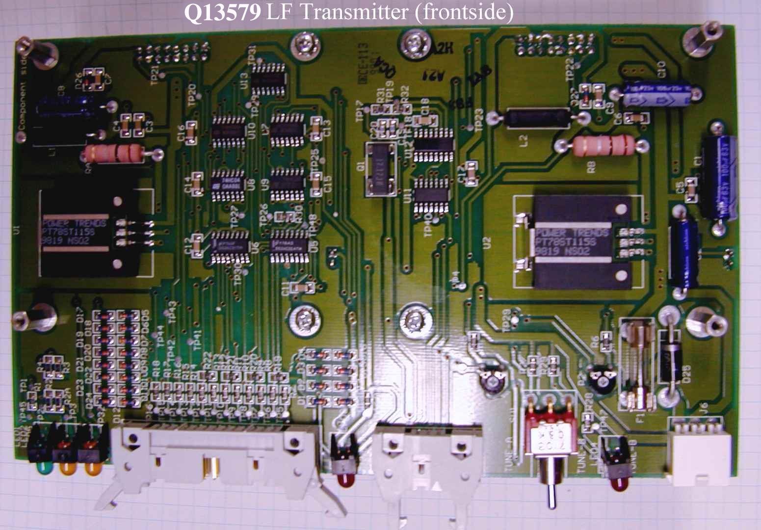
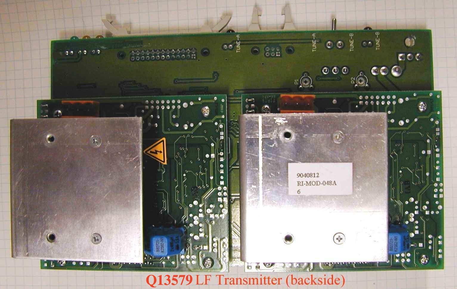
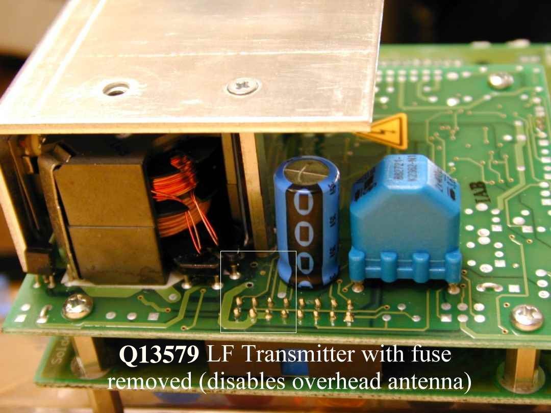
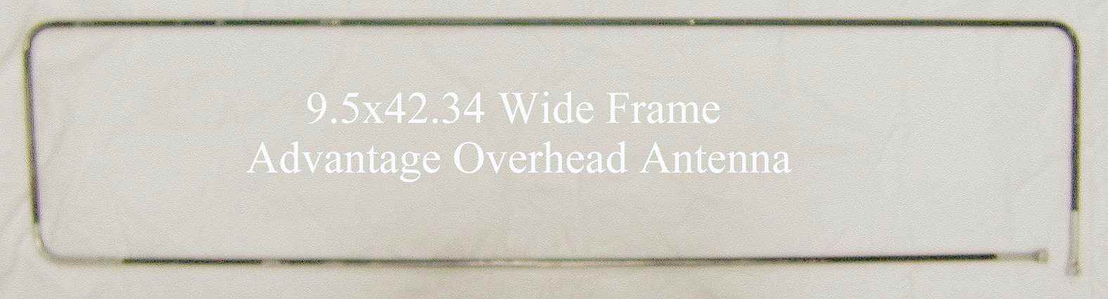
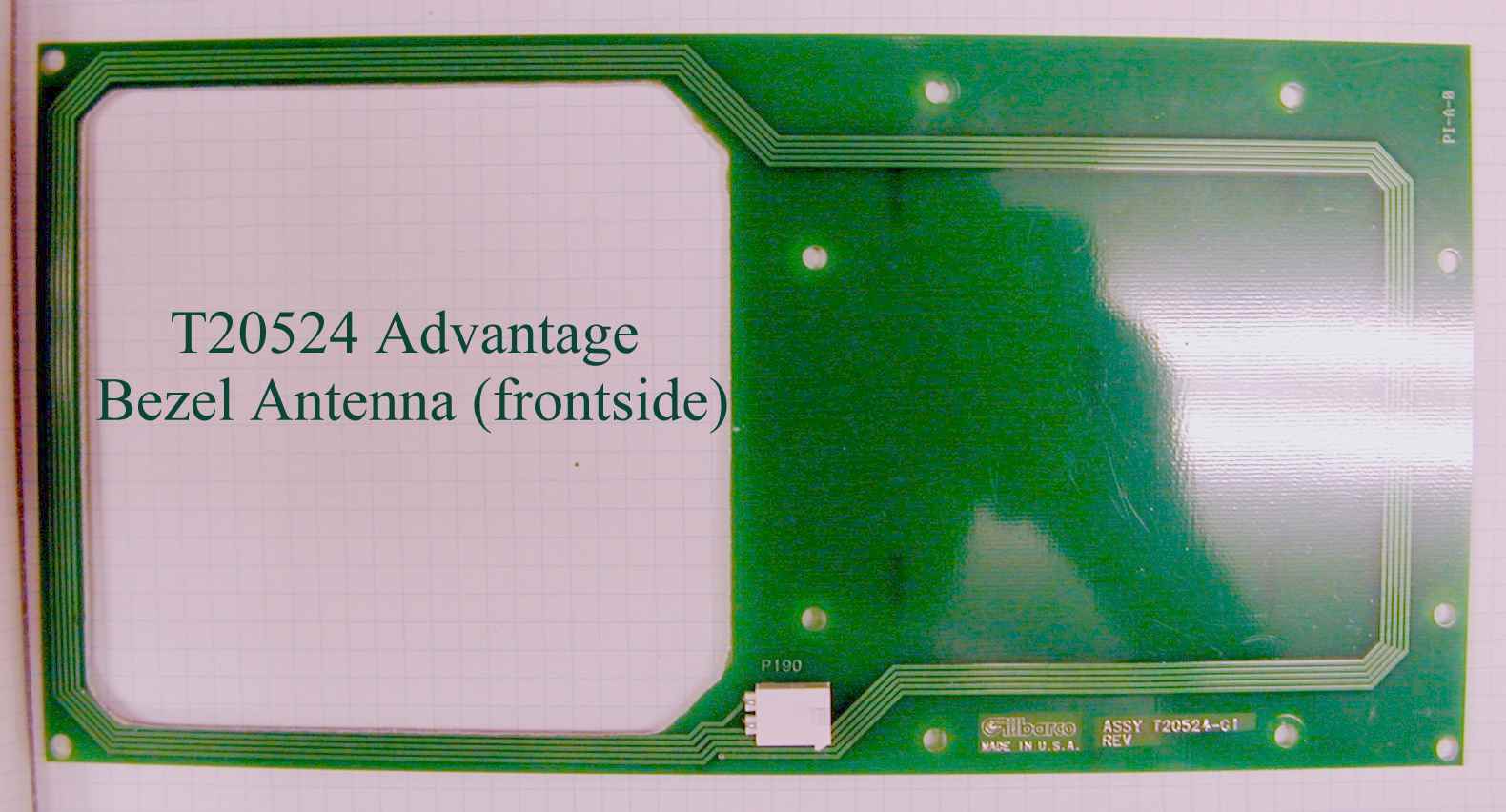
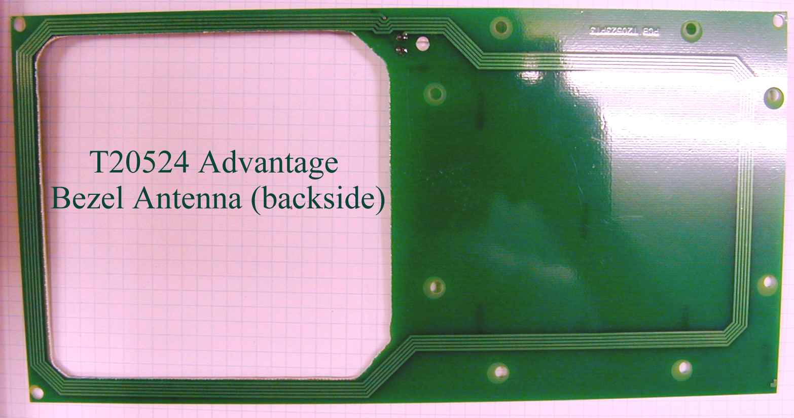
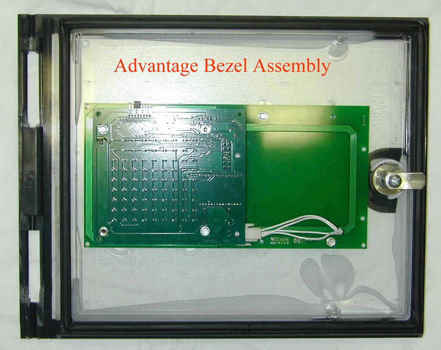
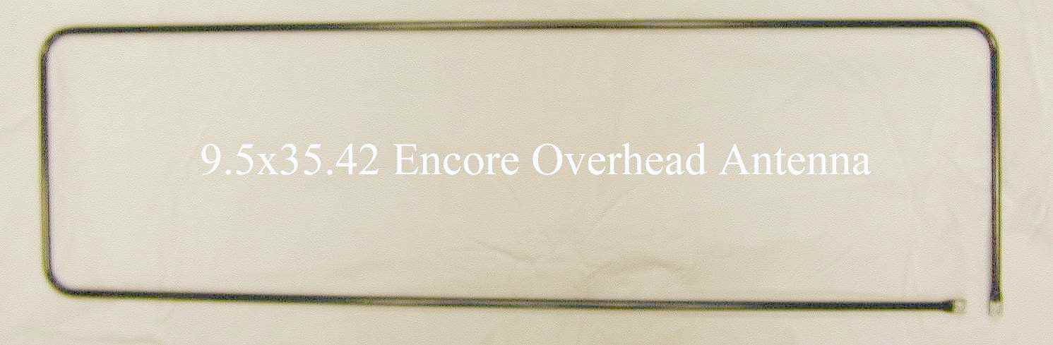
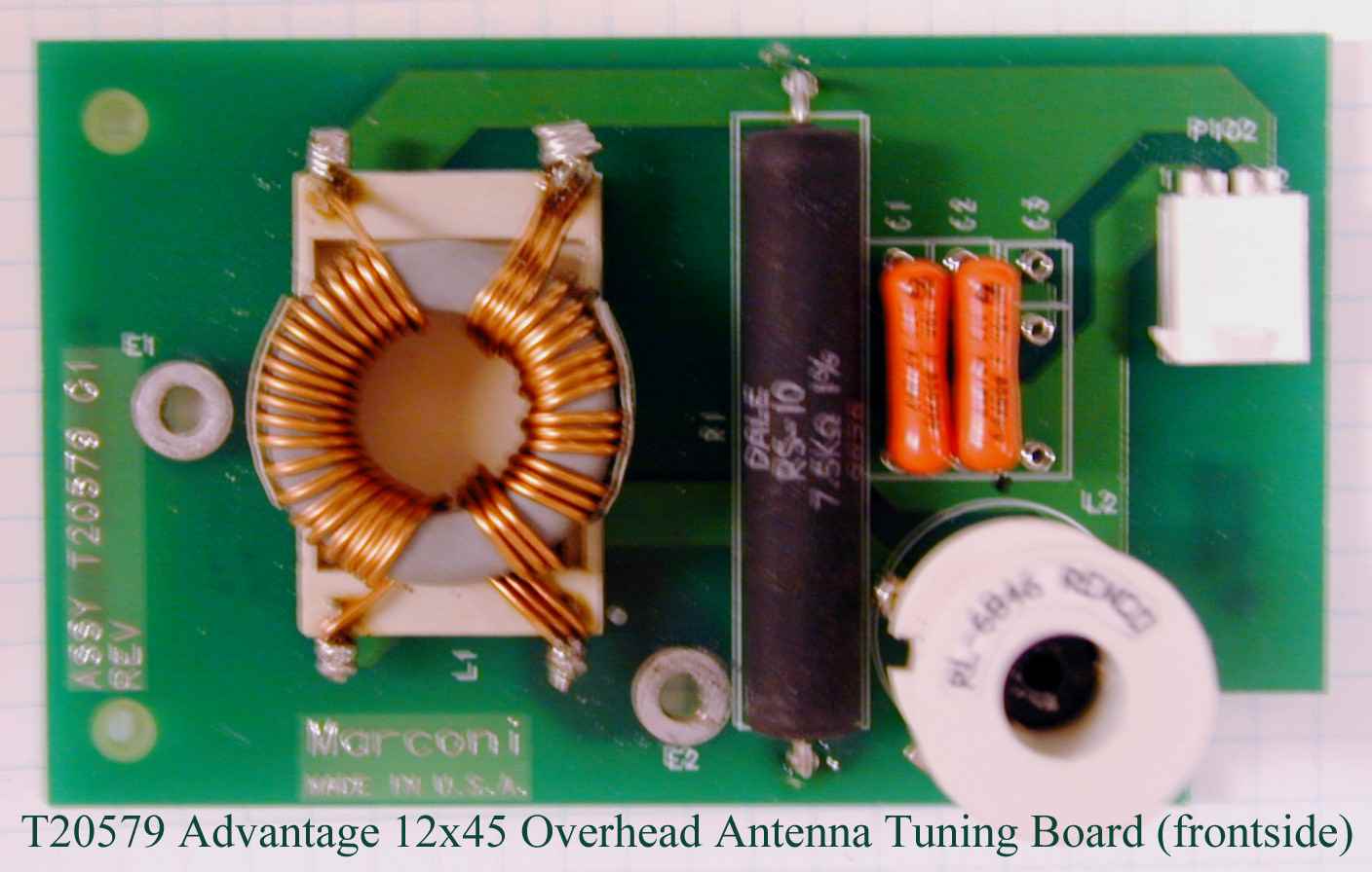
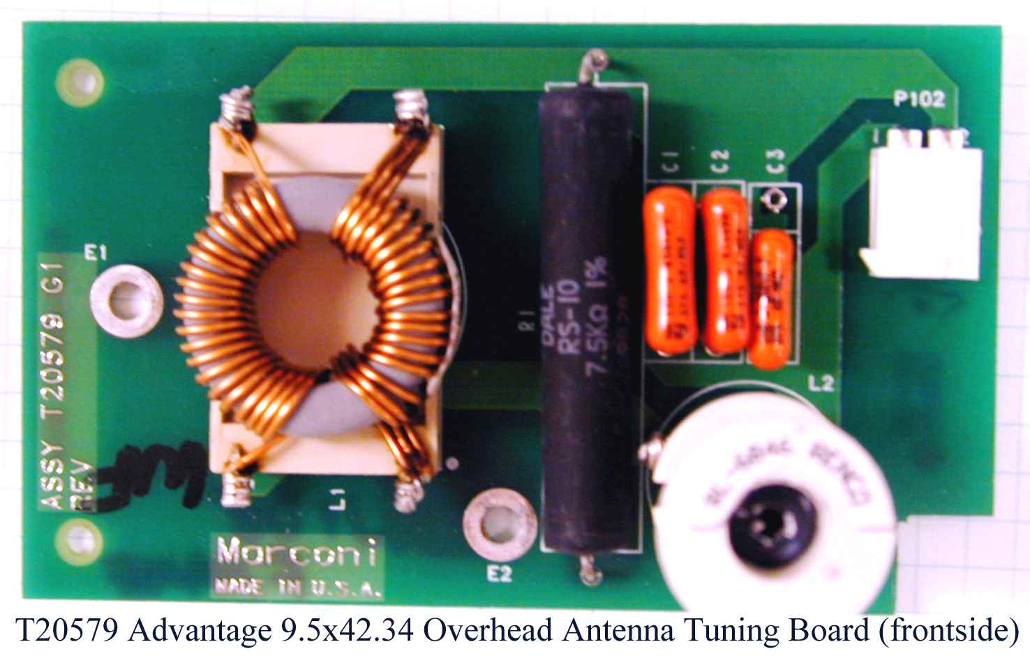
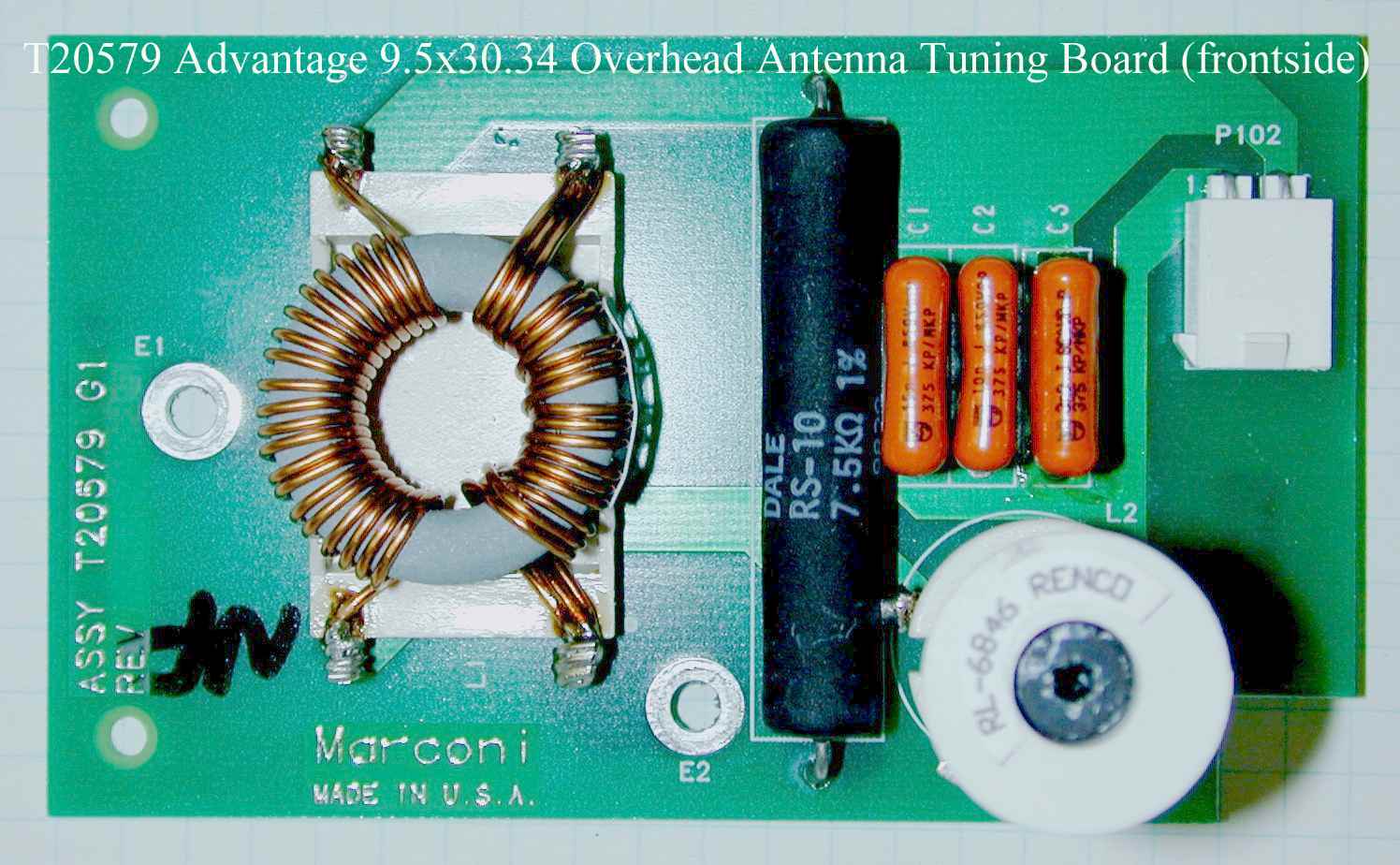
PRELIMINARY MDE-3591A TRIND™ Retrofit Kits C00011-002-XXXX for The Advantrage Series • 3/00 Page 1 Introduction Purpose of this Manual This manual provides instruction for installing TRIND™/TIRIS™ Retrofit Kits C00011-002-XXXX in The Advantage ® Series wide frame units with InfoScreen ® , monochrome CRIND™, or single-line CRIND. The TRIND option allows customers to automatically authorize CRIND-equipped units, using either a hand-held or auto-mounted transponder provided by a major oil company (MOC). Use these kits for one- or two-sided units. Retrofit Kits C00011-002-XXXX are configured according to specific unit requirements. Prerequisites Before installing any TRIND kit, ensure that the existing CRIND contains the following. • Z-180 logic board and software (T17764-XX), which is not configured in TRIND retrofit kit. Refer to MDE-2628, Cash Acceptor Retrofit Assemblies for The Advantage Series Units with CRIND Card Reader in Dispenser Kit C00007-002. • Plastic options doors for single-line/cash acceptor InfoScreen/cash acceptor and monochrome/cash acceptor Important Notice This equipment has been tested and found to comply with the limits for a Class A digital device pursuant to Part 15 of the FCC Rules. These limits are designed to provide reasonable protection against harmful interference when the equipment is operated in a commercial environment. This equipment generates, uses and can radiate radio frequency energy, and if not installed and used in accordance with the instruction manual, may cause harmful interference to radio communications. Operation of this equipment in a residential area is likely to cause harmful interference in which case the user will be required to correct the interference at his own expense. Changes or modifications not expressly approved by the manufacturer could void the user’s authority to operate this equipment. Required Reading Before installing the equipment, the installer must read, understand, and follow: •this manual • NFPA 30A, The Automotive and Marine Service Station Code • NFPA 70, The National Electric Code • applicable federal, state and local codes and regulations • ASC TRIND Technology Update on page 9 Failure to do so may adversely effect the safe use and operation of the equipment. Note: These kits must be installed by a Gilbarco ASC (Authorized Service Contractor) MDE-3591A TRIND™ Transmitter/Receiver in Dispenser Retrofit Kits C00011-002-XXXX Using TIRIS™ Technology Installation PRELIMINARY Introduction Page 2MDE-3591A TRIND ™ Retrofit Kits C00011-002-XXXX for The Advantrage Series • 3/00 Related Documents MDE-2531Pump & Dispenser Start-Up & Service Manual MDE-2562CRIND Service Manual MDE-2628Cash Acceptor Retrofit Assemblies for The Advantage Series with CRIND MDE-2620Graphics Panel Application for The Advantage Series MDE-3640Authorized Service Contractor (ASC) TRIND Installation Tool Kit K94577-01 PT-1728 The Advantage Series Illustrated Parts Manual PT-1736 CRIND Card Reader Illustrated Parts Manual Required Tools The following equipment is needed to install TRIND™ kit C00011-002 • Allen wrench set, American standard • clean cloth or rag • chip extraction tool, e.g., IC extraction, Digikey Part No. K158-ND or equivalent • isopropyl alcohol (part# END-1082) • ladders, style ‘A’, quantity of two (2) •multimeter • pencil or marker •pliers • pocket knife • putty knife or scraper • Q12534 CRIND diagnostic card • ratchet set, standard • screwdrivers, flat and Phillips head • static guard wrist strap • straight edge, 24" • TRIND ASC tool kit (See “ASC TRIND™ Tool Kit K94577-01” on page 3 and refer to MDE-3640, ASC TRIND Installation Tool Kit K94577-01) • work bench or saw horses (packaging cartons may be used as bench) PRELIMINARY MDE-3591A TRIND™ Retrofit Kits C00011-002-XXXX for The Advantrage Series • 3/00 Page 3 Parts Lists Parts Lists C00011-002-XXXX Kit Configurations by Suffix Common Parts for All C00011-002-XXXX Kits ASC TRIND™ Tool Kit K94577-01 -SuffixConfigured ForSee -WF_SThe Advantage ® Series 48" (wide frame) single-sidedpage 4 -WF_DThe Advantage Series 48" (wide frame) double-sidedpage 4 DescriptionAssembly ContainsPart NumberQuantity cable clamp, grayQ13558-0416 cable clamp, grayQ13558-064 cable group assembly (parts shown in columns at right) Q13863-011 cable, TRIND to CRINDR20437-G011 cable, TRIND AC powerR20580-G11 cable, light/multi-protocolM00857A0011 cable, light/multi-protocolM00857A0021 cable, antenna/low frequencyM00878A0021 card cage assemblyT20606-G11 grommet, edgeQ10315-061.5 ft. grommet material, stripQ10277-021 ft. jump jackQ11011-0110 label plate, FCCN23949-011 nut, KepsQ12068-032 screw, sems, 6-32 x 3/8Q12083-131 screw, 8-32 x 3/8Q12083-262 silicone sealant, RTV, tubeEND 15761 software, CRIND™ Bios TRINDK93744-011 tie wrapQ10178-014 washer, flatN16599-481 Tool DescriptionPart Number Quantity co-axial cable toolQ13628-011 field strength sensorQ13626-011 test tag, TI/RFIDcar mountQ13630-011 test tag, TI/RFID hand heldQ13630-021 threaded rod, 3/8-16 x 4"N23880-014 tuning tool, plastic tippedQ13631-011 PRELIMINARY Parts Lists Page 4MDE-3591A TRIND ™ Retrofit Kits C00011-002-XXXX for The Advantrage Series • 3/00 C00011-002-WF S For The Advantage ® Series 48" (wide frame) single-sided units. Kit contains all parts from “Common Parts for All C00011-002-XXXX Kits” on page 3 plus the following. C00011-002-WF D For The Advantage ® Series 48" (wide frame) double-sided units. Kit contains all parts from “Common Parts for All C00011-002-XXXX Kits” on page 3 plus the following. DescriptionPart NumberQuantity antenna assemblyT20632G11 bracket assembly, antenna mountingT20625-012 gasket, 1/2" x 1/16" stripQ11899-121.5 ft. grommet, bulkhead seal Q13570-011 grommet, roundN15941-384 load connector, dummy transmitterR20526-G11 option door assemblyT20613-G11 screw, 10-32 blackK85736-4514 DescriptionPart NumberQuantity antenna assemblyT20632G12 bracket assembly, antenna mountingT20625-012 gasket, 1/2" x 1/16" stripQ11899-123 ft. …
Text truncated - open the document above for the full version.
Cover Letter(s)
N6SMRIR2 – Confidentiality Letter 13536 North Central Expressway, MS 457, Dallas, TX 75243 _____________________________________________________ May 12, 2000 Via Electronic Filing Federal Communications Commission EQUIPMENT APPROVAL SERVICES P.O. Box 358315 Pittsburgh, PA 15251-5315 Re:FCC ID No.: N6SMRIR2 Confirmation Number: EA97464 Dear Sir or Ma’am: Pursuant to 47 C.F.R. § 0.459, Texas Instruments respectfully requests confidential protection of the following documents submitted electronically in furtherance of the above-reference application as containing propriety information listed below: FCC Confidentiality • Electrical Schematics of Data Control Board RI-CTL-DCMA-02. (7 0010-A-02.pdf, Adobe Acrobat file *.pdf, 8 pages total) • Electrical Schematics of LF Transmitter Module Board RI-MOD-048A. (00106A01.pdf, Adobe Acrobat file *.pdf, 3 pages total) • Product Specifications for LF Transmitter Module Board RI-MOD-048A. (110621041.pdf, Adobe Acrobat files *.pdf, 22 pages total) • Product Specifications for Microreader Board RI-STU-MRD1. (027.pdf, Adobe Acrobat files *.pdf, 32 pages total) The reason for request for confidentiality is that these documents contain Texas Instruments proprietary and internal information and it is critical from a product technology and know-how standpoint (hardware and software) that this information remains confidentia l. Should you have any questions regarding the matters addressed herein, please do not hesitate to contact me at (972) 995-0318 ([email protected]). Respectfully submitted, By:/s/ V. C. Kumar V. C. Kumar Programs Manager
Test Report
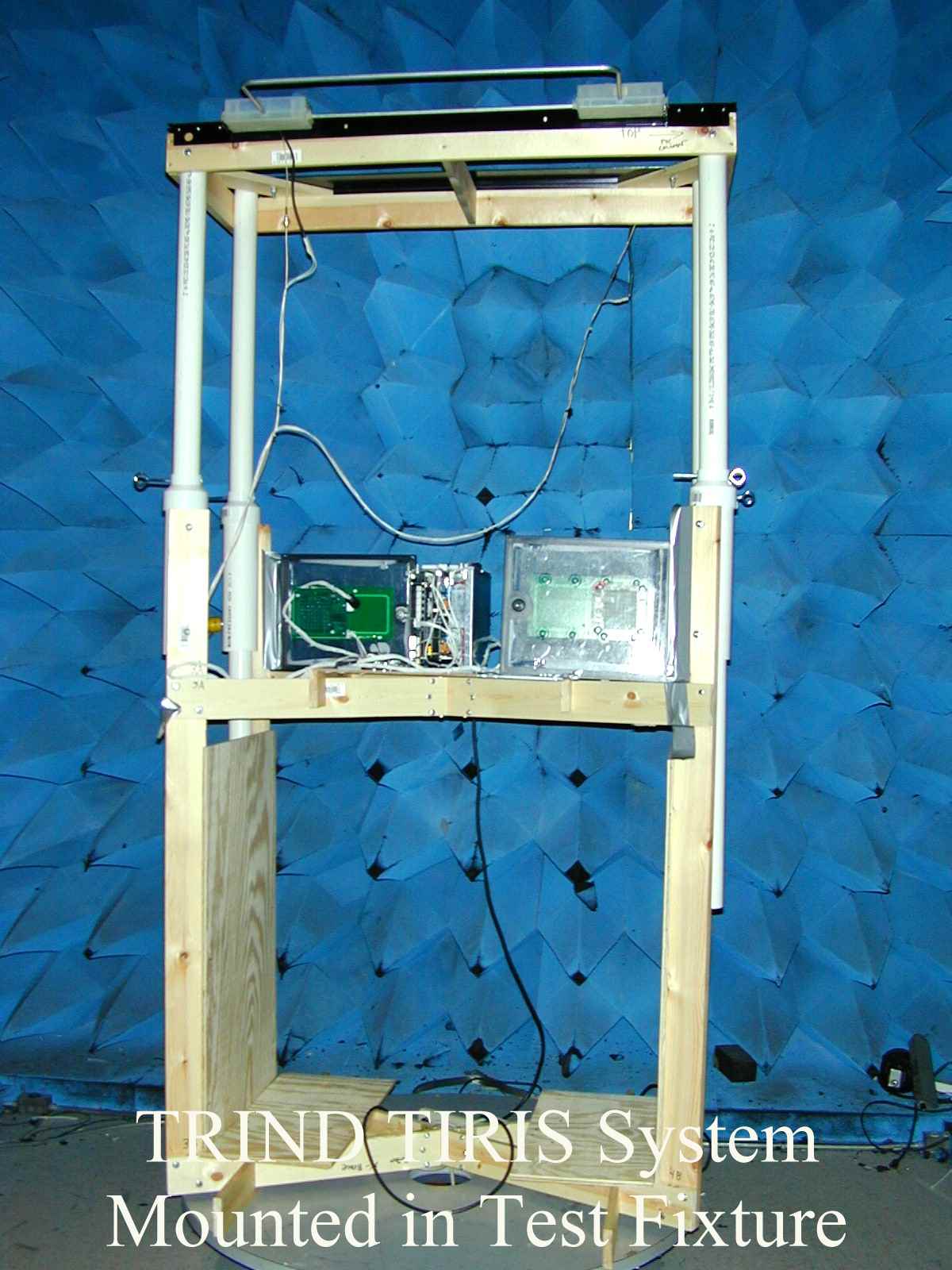
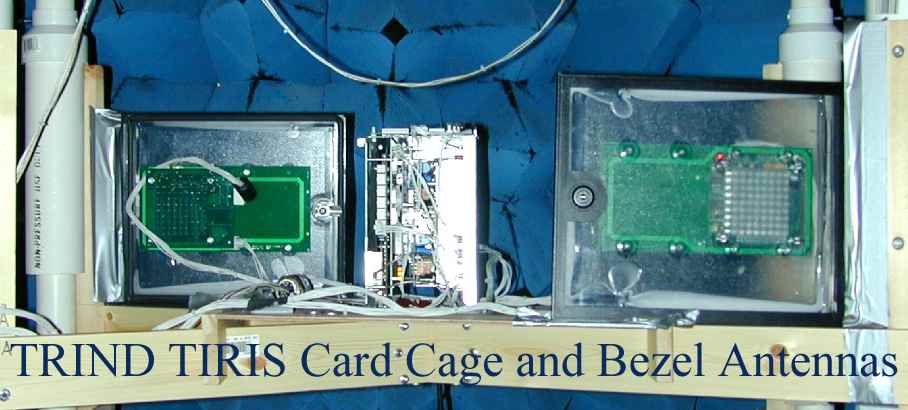
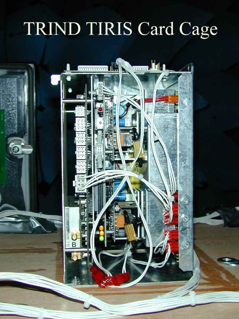
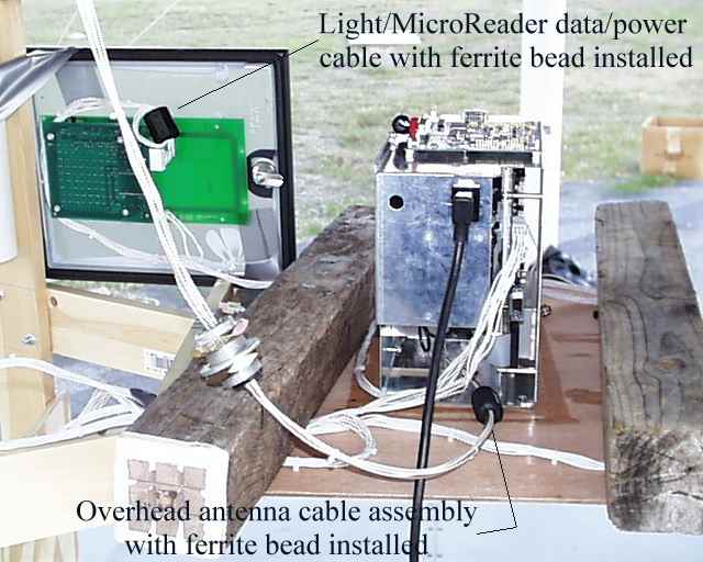
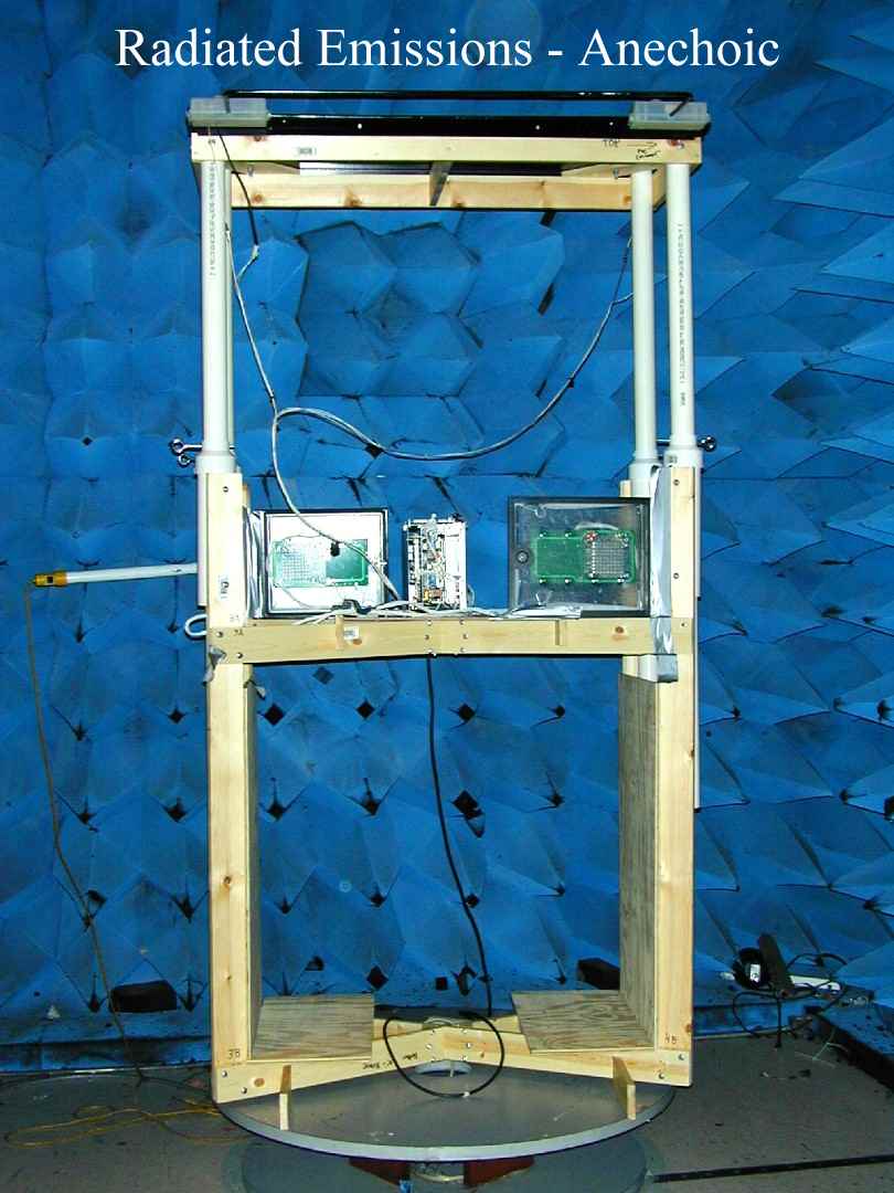
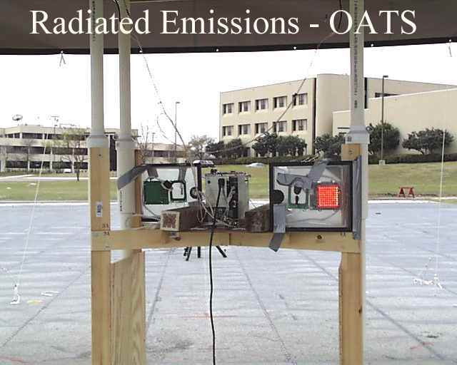
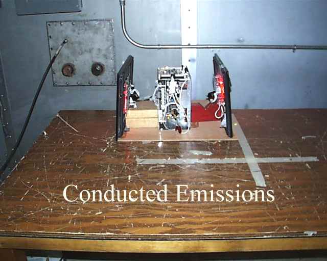
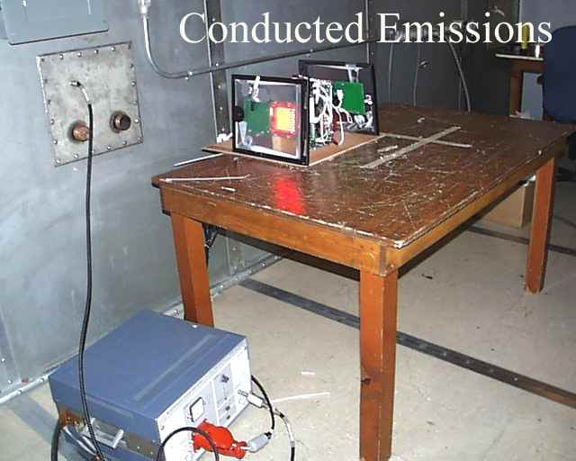
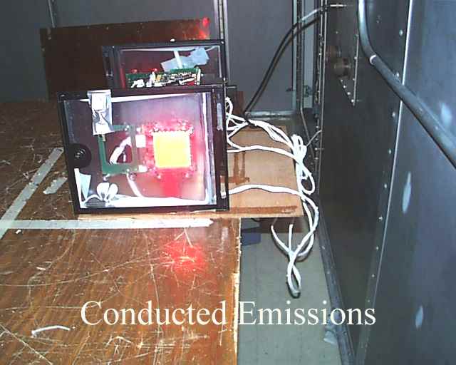
FCC ID: N6SMRIR2 P:\10-3083\005rp t.doc 1 of 37 MEASUREMENT AND TECHNICAL REPORT OF THE MARCONI COMMERCE SYSTEMS TRIND™ TIRIS™ RADIO FREQUENCY IDENTIFICATION DEVICE Southwest Research Institute 6220 Culebra Road San Antonio, Texas 78228-0510 Project 10-3083.01.005 Report Number EMCR 00/012 Prepared for: Marconi Commerce Systems 7300 West Friendly Avenue P.O. Box 22087 Greensboro, NC 27420-2087 Prepared by: Dave Carmony March 2000 Re vie we d by:Approve d by: Ismael Martinez, Jr.James J. Polonis Sr. Engineering TechnologistManager Ele ctromagne tic Compatibility Re se arch Se ctionEle ctromagne tic Compatibility Re se arch Se ction Communications Engine e ring De partme ntCommunications Engine e ring De partme nt FCC ID: N6SMRIR2 P:\10-3083\005rp t.doc 2 of 37 TABLE OF CONTENTS Page List of Tables ................................................................................................................................... 3 1.0General Information............................................................................................................... 4 1.1Product Description............................................................................................................... 4 1.2Related Grants ...................................................................................................................... 4 1.3Tested System Details........................................................................................................... 4 1.4Test Methodology................................................................................................................. 6 1.5Test Facility......................................................................................................................... 6 2.0Product Labeling................................................................................................................... 7 2.1FCC ID Label ....................................................................................................................... 7 2.2Location of Label on EUT...................................................................................................... 7 2.3Label for the Exterior of Devices Incorporating the EUT ........................................................... 7 2.4Supplemental Information to be in the Reader Manual............................................................... 7 3.0System Test Configuration..................................................................................................... 8 3.1Justification.......................................................................................................................... 8 3.2EUT Exercise ..................................................................................................................... 8 3.3Special Accessories .............................................................................................................. 8 3.4Equipment Modification ........................................................................................................ 8 3.5 Configuration of Tested System ............................................................................................. 8 4.0Block Diagram of the TRIND™ TIRIS™ System..................................................................... 9 5.0Conducted and Radiated Measurement Photos ....................................................................... 10 6.0Conducted Emission Data..................................................................................................... 11 6.1Conducted Measurement Data .............................................................................................. 11 6.2Conducted Test Instrumentation ........................................................................................... 11 7.0Radiated Emission Data........................................................................................................ 12 7.1Configurations Tested .......................................................................................................... 12 7.2Radiated Measurement Data ................................................................................................. 12 7.3Test Instrumentation for Radiated Measurements.................................................................... 19 7.4Field Strength Calculation..................................................................................................... 19 Appendix A: Conducted Measurement Plots ...................................................................................... 20 Appendix B: Radiated Measurement Plots ..........................................................................................23 Appendix C: Test Instrumentation ..................................................................................................... 34 Appendix D: Photos of Tested EUT ...................................................................................................36 Appendix E: Photos of Test Setups ................................................................................................... 37 Attachment 1: Functional Description and Block Diagram Attachment 2: Installation Instructions Attachment 3: FCC ID Label Attachment 4: Schematics FCC ID: N6SMRIR2 P:\10-3083\005rp t.doc 3 of 37 LIST OF TABLES TablePage 1.1 TRIND™ TIRIS™ Components ............................................................................................. 5 1.2 Antenna Configurations Tested............................................................................................... 5 6.1Worst Case Conducted Emission Levels .................................................................................11 7.1Configurations Tested For Radiated Emissions .......................................................................12 7.2Measurement of Fundamental Frequency ......................................................................…
Text truncated - open the document above for the full version.
Contact Information
Applicant
Bob Sykes(EMC Engineer)
Technical Contact
Marconi Commerce SystemsLester Ward
[email protected]336-547-5559
7300 West Friendly Avenue · Greensboro, North Carolina · United States
Test Firm
Southwest Research InstituteDavid Carmony
210-684-5111
Technical Specifications
| # | Rule Parts | Frequency Range | Power Output |
|---|---|---|---|
| 1 | 15C | 0.1342 MHz - 0.1342 MHz | - |
Other Applications from Gilbarco Inc.
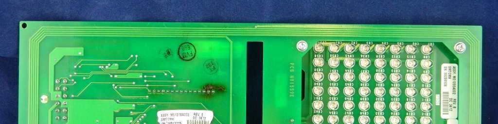
N6SLFSQR
Jun 23, 2015TRIND M01560 Module
Equipment Class
DCD - Part 15 Low Power Transmitter Below 1705 kHz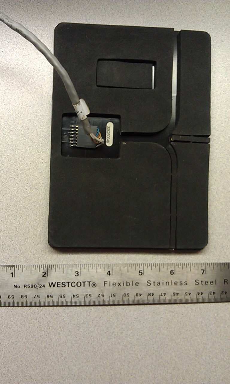
N6SLFMAT
Aug 12, 2013Mat Reader
Equipment Class
DCD - Part 15 Low Power Transmitter Below 1705 kHz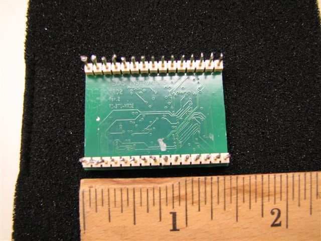
N6SLFECIM
Mar 26, 2013RFID Module
Equipment Class
DCD - Part 15 Low Power Transmitter Below 1705 kHz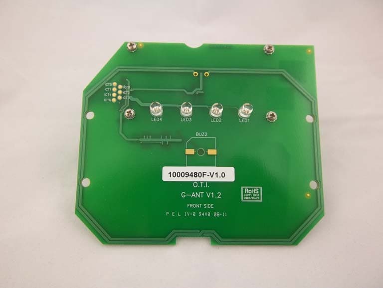
N6SGCM
May 24, 2011Contactless Smart Card Interface
Equipment Class
DXX - Part 15 Low Power Communication Device Transmitter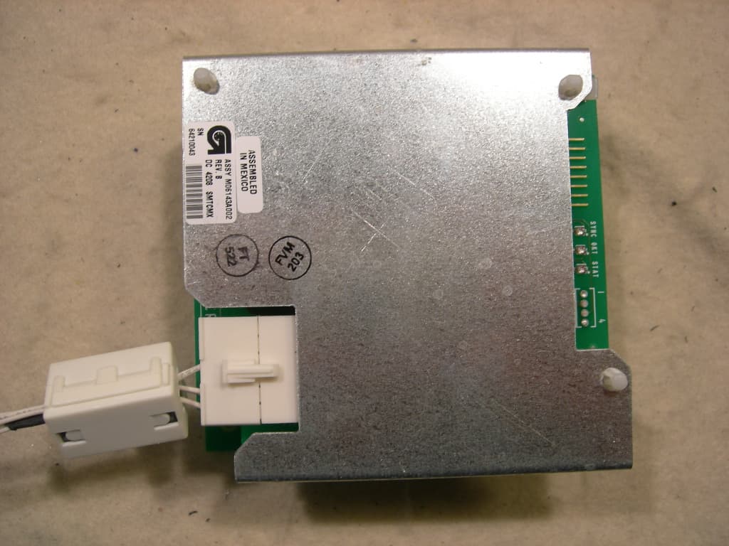
N6SLFTRIND
Jun 10, 2010TRIND RFID Module
Equipment Class
DCD - Part 15 Low Power Transmitter Below 1705 kHz