N6SMRIR3Radio Frequency Identification Device
Gilbarco Inc.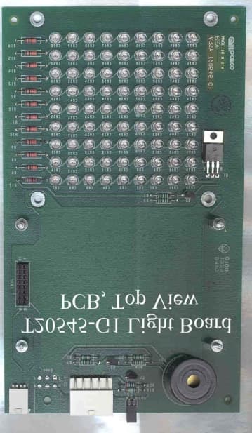
Click to zoom
Application Details
- Equipment Class
- DXX - Part 15 Low Power Communication Device Transmitter
- Date of Grant
- Apr 04, 2001
- Application Purpose
- Original Equipment
- Date of Application
- Aug 29, 2000
- Equipment Note
- Radio Frequency Identification Device
- Frequency Range
- 13.56000000 - 13.56000000
- Company
- Gilbarco Inc.
- Country
- United States
Documents & Files
Document Text
Text extracted from the exhibit documents filed with the FCC. Open a document above to read the original.
Users Manual
PRELIMINARY MDE-3801A TRIND™ Multi 1 Transmitter/Receiver in Dispenser Retrofit Kit • 07/00Page 1 Introduction Purpose of this Manual This manual provides instruction for installing TRIND™ Multi 1 system for use in Marconi products. Important Notice This equipment has been tested and found to comply with the limits for a Class A digital device pursuant to Part 15 of the FCC Rules. These limits are designed to provide reasonable protection against harmful interference when the equipment is operated in a commercial environment. This equipment generates, uses and can radiate radio frequency energy, and if not installed and used in accordance with the instruction manual, may cause harmful interference to radio communications. Operation of this equipment in a residential area is likely to cause harmful interference in which case the user will be required to correct the interference at his own expense. Changes or modifications not expressly approved by the manufacturer could void the user’s authority to operate this equipment. Required Reading If installing the equipment TRIND Multi 1 on gasoline dispensing equipment, the installer must read, understand, and follow: •this manual • NFPA 30A, The Automotive and Marine Service Station Code • NFPA 70, The National Electric Code • applicable federal, state and local codes and regulations Failure to do so may adversely effect the safe use and operation of the equipment. Note: This kit must be installed by a Marconi ASC (Authorized Service Contractor) to insure warranty. Required Tools The following equipment may be needed to install all TRIND™ Multi 1 kits: • Allen wrench set, American standard • clean cloth or rag • chip extraction tool, e.g., IC extraction, Digikey Part No. K158-ND or equivalent • isopropyl alcohol (part# END-1082) • needle nose pliers • nut driver, 1/4'', 3/8'' • pocket knife • Q12534 CRIND diagnostic card • ratchet set, standard • screwdrivers, flat and Phillips head • static guard wrist strap MDE-3801A TRIND™ MULTI 1 Transmitter/Receiver in Dispenser Retrofit Kits C00012-002-XX Installation PRELIMINARY Parts List Page 2MDE-3801A TRIND™ Multi 1 Transmitter/Receiver in Dispenser Retrofit Kit • 07/00 Parts List C00012-002 Kit TRIND Multi 1 kits may be installed on a variety of Host Electronics (HE) systems. All kits contain the parts detailed in table below. However, depending upon type of HE and equipment receiving installation, additional parts or quantities of listed parts may be added to kits as installation specific order entry items. Q13781-01 Cable Group Cable group Q13781-01 for all kits contains the following cables: DescriptionPart NumberQuantity cable group (see table “Q13781-01 Cable Group” on page 2) Q13781-011 card cage assembly T20538-G21 antenna/light assembly .T20582-G1 (see note 1) T20609-G1 (see note 2) M01296A001 (see note 3) (see note 4) jump jackQ11011-0110 label plate, FCCN23936-011 manual, installation instructionsMDE-38011 Notes: 1.For wide frame The Advantage Pumps and Dispensers only. Assembly includes T20545-G2 Light Board and R20718-G1 Antenna Cable 2.For narrow frame The Advantage Pumps and Dispensers only. Assembly includes T20545-G2 Light Board and R20718-G1 Antenna Cable 3.For Marconi Encore Series units only. Assembly includes M001058 Antenna Assembly and M001055 Light Board. 4.Quantities determined at order entry. CablesPart NumberQuantity per kit Gateway to CRIND logicR20437-G011 AC powerR20580-G21 Light/Multi-protocol ReaderR20665-GX (see note 5) (see note 6) Gateway to Light/MPR/Power BoardsR20724-G11 Notes: 5.Cable lengths (-GX) determined at order entry. 6.Quantity determined at order entry. PRELIMINARY MDE-3801A TRIND™ Multi 1 Transmitter/Receiver in Dispenser Retrofit Kit • 07/00Page 3 Safety Information Safety Information Alert Symbol and Signal Words Alert Symbol: This is a standard ANSI* approved alert symbol. When you see this symbol, be alert to the potential for a personal injury. * Reference American National Standard Bulletins ANSI Z535. Signal Words: These signal words alert you to important safety hazards. Safety Symbols: The following safety symbols are used throughout this manual to alert you to personal safety hazards and precautions. Explosive Flammable Electrical hazard Use safety barricades No people in area No vehicles in area Use emergency power disconnect No open flames No smoking No power tools Wear eye protection Read all related manuals Clean up spills Turn power off ! WARNING The hazard or unsafe practice may result in severe injury or death. ! CAUTION The hazard or unsafe practice could result in minor injury. The hazard or unsafe practice will result in severe injury or death. ! DANGER OFF PRELIMINARY Safety Information Page 4MDE-3801A TRIND™ Multi 1 Transmitter/Receiver in Dispenser Retrofit Kit • 07/00 Use Electrostatic Discharge Precautions Place yourself at a neutral static-free potential by doing the following: 1Touch an unpainted metal surface. 2Use a wrist strap connected to a grounded metal frame or chassis. Note: Failure to use electrostatic discharge precautions may damage electronic components and void warranty. Make sure all power has been removed from unit and CRIND. Follow OSHA Lock-Out and Tag-Out Requirements OSHA Standard 29 CFR 1910-147 Control of Hazardous Energy Sources (Lock-Out/Tag-Out) covers ways to avoid personal injury if power is turned on or fuel pressure is applied unexpectedly while servicing equipment. The rule requires that equipment power and fuel under pressure be turned off and the device (breaker, valve, etc.) locked or labeled with a warning tag. Read OSHA Standard 29 CFR 1910-147 Control of Hazardous Energy Sources (Lock-Out/ Tag-Out). Station employees and service contractors need to understand and comply with this program completely to ensure safety while the equipment is down. Tag-Out and Lock-Out Procedure Use plastic warning tags with signature/date blanks for Tag-Out. Sign and date them at shut down. Attach tags with plas…
Text truncated - open the document above for the full version.
Cover Letter(s)
Marconi Commerce Systems Inc. 7300 W. Friendly Avenue P. O. Box 22087 Greensboro, NC 27420-2087 USA Telephone: 336 547 5000 Fax: 336 292 8871 Telex: 4949970 Web site: www.marconicommerce.com August 30, 2000 Federal Communications Commission EQUIPMENT APPROVAL SERVICES P.O. Box 358315 Pittsburgh PA 15251-5315 Confirmation Number (EA98605) FCC ID number (N6SMRIR3). *** Marconi Commerce Systems Inc is requesting and paying for confidentiality for proprietary schematics, electrical block diagram, and operational descriptions. These items should not be routinely available. This request is per Title 47 sections 0.457 and 0.459.*** Sincerely, Lester Ward Marconi Commerce Systems Inc
Test Report
FCC ID: N6SMRIR3 P:\10-03628\fcc_1.doc Page 1 of 41 MEASUREMENT AND TECHNICAL REPORT ON THE MARCONI COMMERCE SYSTEMS TRIND™ MULTI 1™ Southwest Research Institute 6220 Culebra Road San Antonio, Texas 78228-0510 Project 10-03628.01.001 Report Number EMCR 00/034 Prepared for: Marconi Commerce Systems 7300 West Friendly Avenue P.O. Box 22087 Greensboro, NC 27420-2087 Prepared by: David A. Carmony May 2000 Reviewed by:Approved by: _____________________________________________________________________________ Ismael Martinez, Jr.James J. Polonis Senior Engineering TechnologistManager Electromagnetic Compatibility Research SectionElectromagnetic Compatibility Research Section Communications Engineering DepartmentCommunications Engineering Department FCC ID: N6SMRIR3 P:\10-03628\fcc_1.doc Page 2 of 41 TABLE OF CONTENTS Page List of Tables ............................................................................................................................................... 3 1.0General Information ........................................................................................................................ 4 1.1Product Description......................................................................................................................... 4 1.2Related Grants................................................................................................................................. 4 1.3Tested System Details ..................................................................................................................... 4 1.4Test Methodology ........................................................................................................................... 5 1.5Test Facility..................................................................................................................................... 5 2.0Product Labeling ............................................................................................................................. 6 2.1FCC ID Label .................................................................................................................................. 6 2.2Location of Label on EUT .............................................................................................................. 6 2.3Label for the Exterior of Devices Incorporating the EUT .............................................................. 6 2.4Supplemental Information to be in the Reader Manual .................................................................. 6 3.0System Test Configuration.............................................................................................................. 7 3.1Justification ..................................................................................................................................... 7 3.2EUT Exercise ................................................................................................................................. 7 3.3Special Accessories......................................................................................................................... 7 3.4Equipment Modification ................................................................................................................. 7 3.5 Configuration of Tested System ..................................................................................................... 7 3.6Antenna System .............................................................................................................................. 7 4.0Block Diagram of the TRIND™ MULTI 1™ ................................................................................. 8 5.0Conducted and Radiated Measurement Photos..................................................................... ........ 9 6.0Conducted Emission Data ............................................................................................................. 10 6.1Conducted Measurement Data ...................................................................................................... 10 6.2Conducted Test Instrumentation ................................................................................................... 10 7.0Radiated Emission Data ................................................................................................................ 11 7.1Radiated Measurement Data ......................................................................................................... 11 7.2Test Instrumentation for Radiated Measurements ........................................................................ 19 7.3Field Strength Calculation ............................................................................................................ 19 Appendix A: Conducted Measurement Plots ............................................................................................. 20 Appendix B: Radiated Signature Measurement Plots................................................................................ 25 Appendix C: Test Instrumentation ............................................................................................................. 38 Appendix D: Photos of Tested EUT .......................................................................................................... 40 Appendix E: Photos of Test Setups............................................................................................................ 41 Attachment 1: Functional Description and Block Diagram Attachment 2: Installation Instructions Attachment 3: FCC ID Label Attachment 4: Schematics FCC ID: N6SMRIR3 P:\10-03628\fcc_1.doc Page 3 of 41 LIST OF TABLES TablePage 1.1System Components ......................................................................................................................... 5 6.1Worst Case Conducted Emission Levels ....................................................................................... 10 7.1Measuremen…
Text truncated - open the document above for the full version.
Test Report
Below please find the answer to the question asked on 2/14/2001. _______________________________________________________________________ Re:FCC ID N6SMRIR3 Applicant:Marconi Commerce Systems Inc. Correspondence Reference Number:18100 731 Confirmation Number:EA98605 1) Please clarify what the input frequency RANGE is? What is the input bandwidth / frequency range of the receiver? It should be wide enough to capture the transmitted signal but may be wider to accomodate any deviation or stability in the design. An illumination frequency (13.56MHz) is used to power the tag and pass data, but the responses from the tag are returned in modulation sidebands centered around the illumination frequency. For a graphical representation of these sidebands and associated spectral content see the graph below. 484.28 kHz 484.28 kHz 423.75 kHz423.75 kHz ~ 60 kHz~ 60 kHz ISO 15693 f c = carrier frequency = 13.56 MHz 13.56 MHz Frequency f s 2 f s 2 f s 1 f s 1 Subcarrier frequency: f s1 = f c /32 (423.75 kHz) (if 1 subcarrier) or f s1 = f c /32 (423.75 kHz) and f s2 = f C /28 (484.28 kHz) (if two subcarriers are used). The transponder typically (when using two subcarriers) switches rapidly between f s1 and f s2 as shown in the figure above. Theoretically this should be therefore a “bandwidth” of ~ 60 Hz. However, in reality, this is ~ 300 kHz (each side). For the ISO 14443 functionality, the f s value is 847 kHz (one subcarrier) with “bandwidth” of 600 kHz (each side).
Contact Information
Applicant
Bob Sykes(EMC Engineer)
Technical Contact
Marconi Commerce Systems, Inc.Lester G Ward
[email protected](336) 547 5559
7300 West Friendly Avenue · Greensboro, North Carolina · United States
Non-Technical Contact
Marconi Commerce Systems, Inc.Lester G Ward
[email protected](336) 547 5559
Test Firm
Southwest Research InstituteDavid Carmony
210-684-5111
Technical Specifications
| # | Rule Parts | Frequency Range | Power Output |
|---|---|---|---|
| 1 | 15C | 13.56 MHz - 13.56 MHz | - |
Other Applications from Gilbarco Inc.
N6SLFSQR
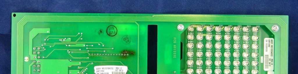
Jun 23, 2015TRIND M01560 Module
Equipment Class
DCD - Part 15 Low Power Transmitter Below 1705 kHz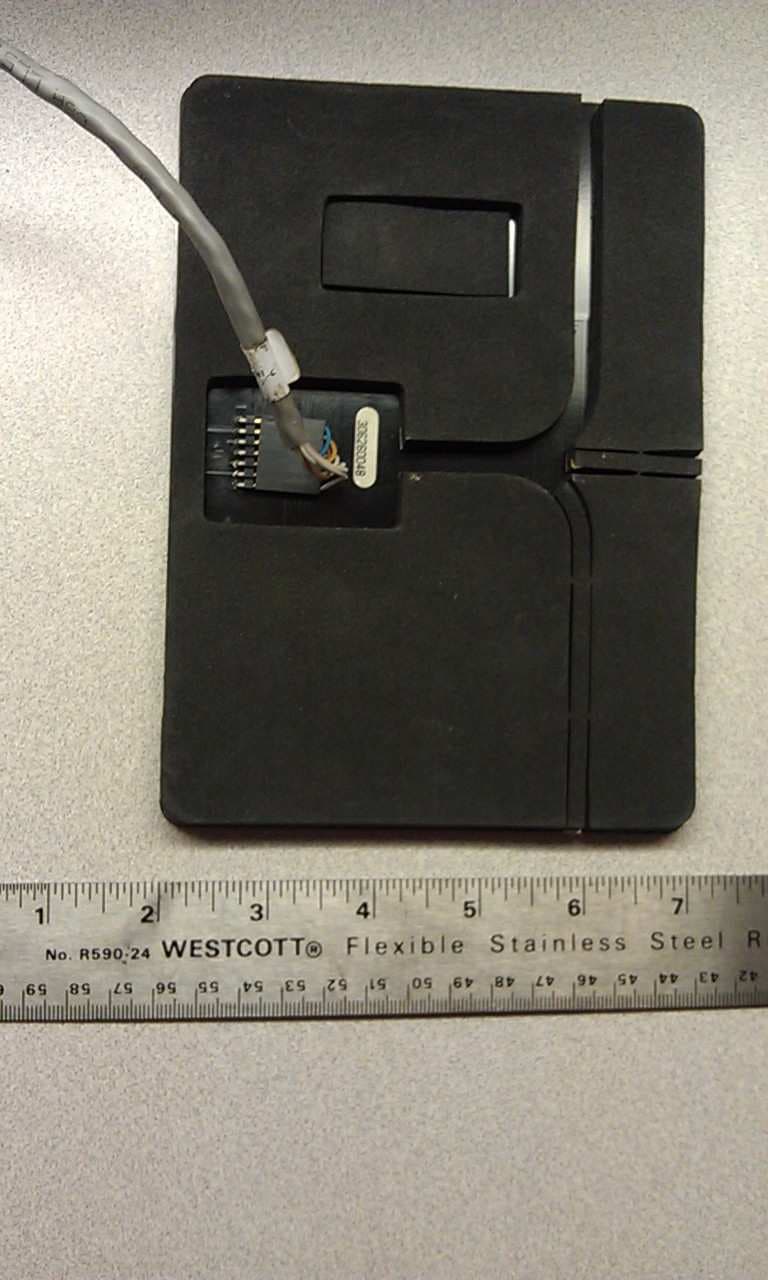
N6SLFMAT
Aug 12, 2013Mat Reader
Equipment Class
DCD - Part 15 Low Power Transmitter Below 1705 kHz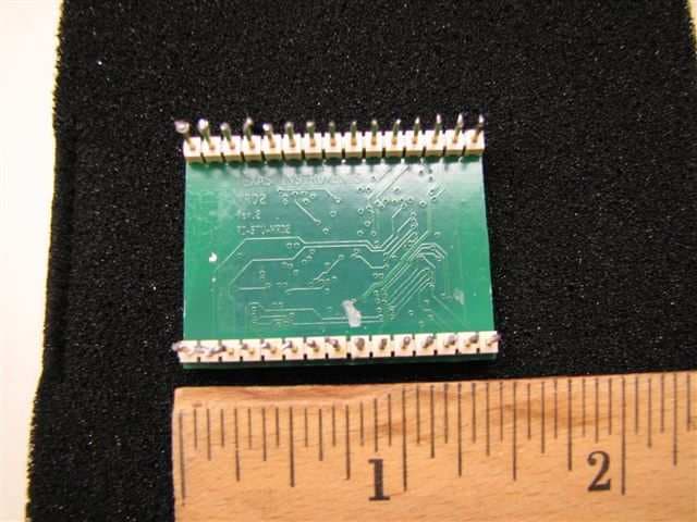
N6SLFECIM
Mar 26, 2013RFID Module
Equipment Class
DCD - Part 15 Low Power Transmitter Below 1705 kHz
N6SGCM
May 24, 2011Contactless Smart Card Interface
Equipment Class
DXX - Part 15 Low Power Communication Device Transmitter
N6SLFTRIND
Jun 10, 2010TRIND RFID Module
Equipment Class
DCD - Part 15 Low Power Transmitter Below 1705 kHz