N6SMRIR6Radio Frequency Identification Device (Limited Mod
Gilbarco Inc.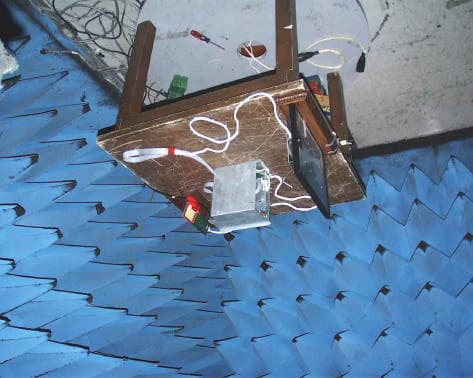
Click to zoom
Application Details
- Equipment Class
- DXX - Part 15 Low Power Communication Device Transmitter
- Date of Grant
- Mar 08, 2001
- Application Purpose
- Original Equipment
- Date of Application
- Jan 07, 2001
- Equipment Note
- Radio Frequency Identification Device (Limited Mod
- Frequency Range
- 0.13400000 - 0.13400000
- Company
- Gilbarco Inc.
- Country
- United States
Documents & Files
Document Text
Text extracted from the exhibit documents filed with the FCC. Open a document above to read the original.
Users Manual
PRELIMINARY FCC 11/30 MDE-3883 TRIND Retrofit Kits C00011-005 • 10/00 Page 1 Introduction Purpose of this Manual This manual provides instruction for installing TRIND™ Retrofit Kits C00011- 005-XX in The Advantage ® Series wide frame and narrow frame units and MPD ® 3 units with InfoScreen ® , monochrome CRIND ® , or single-line CRIND. The TRIND option allows customers to automatically authorize CRIND-equipped units using a hand-held transponder tag provided by a major oil company (MOC). Use these kits for one- or two-sided units. Prerequisites Before installing the TRIND kit, ensure that the existing CRIND has the Z-180 logic board T17764-XX, which is not provided in TRIND retrofit kit. Important Notice This equipment has been tested and found to comply with the limits for a Class A digital device pursuant to Part 15 of the FCC Rules. These limits are designed to provide reasonable protection against harmful interference when the equipment is operated in a commercial environment. This equipment generates, uses and can radiate radio frequency energy, and if not installed and used in accordance with the instruction manual, may cause harmful interference to radio communications. Operation of this equipment in a residential area is likely to cause harmful interference in which case the user will be required to correct the interference at his own expense. Changes or modifications not expressly approved by the manufacturer could void the user’s authority to operate this equipment. Required Reading Before installing the equipment, the installer must read, understand, and follow: •this manual •NFPA 30A, The Automotive and Marine Service Station Code •NFPA 70, The National Electric Code •applicable federal, state and local codes and regulations Failure to do so may adversely effect the safe use and operation of the equipment. Note: This kit must be installed by a Gilbarco ASC (Authorized Service Contractor) to insure warranty. MDE-3883 TRIND™ Transmitter/Receiver in Dispenser Retrofit Kits C00011-005-XX Installation Introduction Page 2MDE-3883 TRIND Retrofit Kits C00011-005 • 10/00 PRELIMINARY FCC 11/30 Related Documents MDE-2531Pump & Dispenser Start-Up & Service Manual MDE-2562CRIND Service Manual MDE-2628Cash Acceptor Retrofit Assemblies for The Advantage Series with CRIND MDE-2620Graphics Panel Application for The Advantage Series PT-1728 The Advantage Series Illustrated Parts Manual PT-1736 CRIND Card Reader Illustrated Parts Manual Required Tools The following equipment is needed to install all TRIND™ Multi 1 kits: •Allen wrench set, American standard •clean cloth or rag •chip extraction tool, e.g., IC extraction, Digikey Part No. K158-ND or equivalent •isopropyl alcohol (part# END-1082) •needle nose pliers •nut driver, 1/4'', 3/8'' •pocket knife •Q12534 CRIND diagnostic card •ratchet set, standard •screwdrivers, flat and Phillips head •static guard wrist strap The following additional tools are required if kit is to be installed on wide frame units with call or stop button on existing right options door: •center punch •deburring tool or round file •hand drill, battery electric or pneumatic •light hammer •pilot drill bit (between 3/32” and 1/4”) and 7/8” drill bit •standard tape measure or rule MDE-3883 TRIND Retrofit Kits C00011-005 • 10/00 Page 3 Parts Lists PRELIMINARY FCC 11/30 Parts Lists TRIND Software CRIND BIOS TRIND software K93744-XX is an order entry item for all kits. Q13863-04 Cable Group for All The Advantage Series Kits Cable group Q13863-04 for all kits contains the following cables: C00011-005 Kits for The Advantage Series Wide Frame Units Kits C00011-005-WF-D (dual-sided) and C00011-005-WF-S (single-sided) for The Advantage Series Wide Frames (48’’) contain the following parts. CablesPart NumberQuantity per kit Gateway to CRIND logicR20437-G011 AC powerR20580-G11 Light/Multi-protocol ReaderR20773-G22 DescriptionPart NumberQuantity cable clamp, grayQ13558-0416 cable groupQ13863-04For components see table “Q13863-04 Cable Group for All The Advantage Series Kits” on page 3. cable tieQ10178-014 card cage assembly T20606-G3 (see note 3)1 door assembly, right options clear with TRIND T20613-G1 or T20613-G2 (see note 1) 1 per side graphics, right option doorAD05002GW00X(see note 2) grommet strip, solidQ10315-011.5 ft. jump jackQ11011-014 label plate, FCCN23949-061 manual, installation instructionsMDE-38831 nutQ12068-032 screw, phillips 6-32Q12083-131 screw, phillips 8-32Q12083-262 Notes: 1. T20613-02 door assembly is call/stop button ready. 2. Right Option Door Graphics AD05002GW00X are an order entry item. 3. Some kits may contain a T20606-G4 Card Cage. Only differences for installation consist of location of Gateway board (on top of card cage in -G4 units, within card cage for -03 units) and card cage harness cables for connecting to R20773-G2 door cables. All harness cable connections are identical between -G3 and -G4 card cages. See “Addressing Gateway Board” on page 35. Parts Lists Page 4MDE-3883 TRIND Retrofit Kits C00011-005 • 10/00 PRELIMINARY FCC 11/30 C00011-005 Kits for The Advantage Series Narrow Frame Units Kits C00011-005-NF-D (dual-sided) and C00011-005-NF-S (single-sided) for The Advantage Series Narrow Frames (36’’) contain the following parts. DescriptionPart NumberQuantity cable clamp, grayQ13558-0416 cable groupQ13863-04For components see table “Q13863-04 Cable Group for All The Advantage Series Kits” on page 3. cable tieQ10178-014 card cage assembly T20606-G3 (see note 1) 1 door assembly, right options clear with TRIND T20614-G11 per side graphics, right option doorAD02002GN00X(see note 2) grommet strip, solidQ10315-011.5 ft. jump jackQ11011-014 label plate, FCCN23949-061 manual, installation instructionsMDE-38831 nutQ12068-032 screw, phillips 6-32Q12083-131 screw, phillips 8-32Q12083-262 Notes: 1. Some kits may contain a T20606-G4 Card Cage. Only differences for installation consist of location of Gateway board (on top of card cage in -G4 units, within card…
Text truncated - open the document above for the full version.
Users Manual
N6SMRIR6 – Confidentiality Letter 13536 North Central Expressway, MS 457, Dallas, TX 75243 _____________________________________________________ January 16, 2001 Via Electronic Filing Federal Communications Commission EQUIPMENT APPROVAL SERVICES P.O. Box 358315 Pittsburgh, PA 15251-5315 Re: FCC ID No.: N6SMRIR6 Confirmation Number: EA99709 Dear Sir or Ma’am: Pursuant to 47 C.F.R. § 0.459, Texas Instruments respectfully requests confidential protection of the following document submitted electronically in furtherance of the above-reference application as containing propriety information listed below: FCC Confidentiality • Electrical Schematics of Microreader Board RI-STU-MRD1. (RISTUMRD1.pdf, Adobe Acrobat files *.pdf, 1 page total). The reason for request for confidentiality is that this document contains Texas Instruments proprietary and internal information. It is critical from a product technology and know-how standpoint (hardware and software) that this information remains confidential. Should you have any questions regarding the matters addressed herein, please do not hesitate to contact me at (972) 575-2484 ([email protected]). Respectfully submitted, By: /s/ V. C. Kumar V. C. Kumar Strategic Marketing / Business Development
Attestation Statements
Marconi Commerce Systems is requesting Limited (see question 4) Modular Approval for FCC ID. N6SMRIR6. The following provides responses to the 8 questions that a specified in PART 15 UNLICENSED MODULAR TRANSMITTER APPROVAL (DA 00-1407Released: June 26, 2000). PART 15 UNLICENSED MODULAR TRANSMITTER APPROVAL In order to obtain a modular transmitter approval, a cover letter requesting modular approval must be submitted and the numbered requirements identified below must be addressed in the application for equipment authorization. 1. The modular transmitter must have its own RF shielding. This is intended to ensure that the module does not have to rely upon the shielding provided by the device into which it is installed in order for all modular transmitter emissions to comply with Part 15 limits. It is also intended to prevent coupling between the RF circuitry of the module and any wires or circuits in the device into which the module is installed. Such coupling may result in non- compliant operation. The sheet metal hardware of the “card cage” illustrated in Marconi P/N T20606 G3 was designed for mechanical protection and physical assembly. These sheet metal brackets keep wiring and unwanted objects away from the Gateway Board and power supply components. The Regulator Board (Marconi P/N T20314 G1) has its own shield to reduce EMI effects of the power supply circuitry and to provide mechanical protection. 2. The modular transmitter must have buffered modulation/data inputs (if such inputs are provided) to ensure that the module will comply with Part 15 requirements under conditions of excessive data rates or over-modulation. The modular transmitter has three data lines (two internal and one external) in the system. Two RS-232 internal lines connect the Enhanced Gateway Board (Marconi P/N T20678 G1) to each bezel board (includes the Texas Instruments microreader). These lines pass transponder serial numbers and on/off commands of the recognition light. There are no commands from the DCB that can change performance and RFID functionality of the microreader. One TTL line connects the Enhanced Gateway Board to the fuel dispenser. It passes transponder serial number and authentication code to the dispenser electronics for communication to the point-of-sale (POS) system for credit verification. Once the credit is verified, the POS system instructs the transmitter module to keep the recognition light on or to shut it off. 2 3. The modular transmitter must have its own power supply regulation. This is intended to ensure that the module will comply with Part 15 requirements regardless of the design of the power supplying circuitry in the device into which the module is installed. The T20606 G3 card cage assembly includes a power supply, which provides power to all components of the modular transmitter system. It down converts 120 VAC to 24 VAC using a Class II step-down energy limited transformer (Marconi P/N R20719 G1). The 24 VAC is rectified and buck converted to +22.5 VDC and +5 VDC via a switching power supply (Marconi P/N T20314 G1). 4. The modular transmitter must comply with the antenna requirements of Section 15.203 and 15.204(c). The antenna must either be permanently attached or employ a “unique” antenna coupler (at all connections between the module and the antenna, including the cable). Any antenna used with the module must be approved with the module, either at the time of initial authorization or through a Class II permissive change. The “professional installation” provision of Section 15.203 may not be applied to modules. This device does not meet the unique connector requirements identified in Section 15.203 and 15.204(c). However, this system was designed and will be marketed for commercial use only. Only professionals will install the device. It will never be sold or used in residential applications. In the commercial environments such as retail fueling, technicians have to be trained and licensed to install and service both electrical and mechanical hardware. Therefore, the device should be considered for a “limited modular approval.” 5. The modular transmitter must be tested in a stand-alone configuration, i.e., the module must not be inside another device during testing. This is intended to demonstrate that the module is capable of complying with Part 15 emission limits regardless of the device into which it is eventually installed. Unless the transmitter module will be battery powered, it must comply with the AC line conducted requirements found in Section 15.207. AC or DC power lines and data input/output lines connected to the module must not contain ferrites, unless they will be marketed with the module (see Section 15.27(a)). The length of these lines shall be length typical of actual use or, if that length is unknown, at least 10 centimeters to insure that there is no coupling between the case of the module and supporting equipment. Any accessories, peripherals, or support equipment connected to the module during testing shall be unmodified or commercially available (see Section 15.31(i)). As the photographs and report indicates, the device was tested in a stand-alone configuration and not inside another device. It does not contain any ferrites that will not be marketed with the module. The device was tested with cables of a length typical of actual use that are greater than 10 centimeters long. There were no accessories, peripherals, or support equipment connected to the module. The module interfaces with a fuel dispenser, which is the device into which the module is installed in its final application. 6. The modular transmitter must be labeled with its own FCC ID number, and, if the FCC ID is not visible when the module is installed inside another device, then the outside of the device into which the module is installed must also display a label referring to the enclosed module. This exterior label can use wording such as the following: “Contains Transmitter 3 Module FC…
Text truncated - open the document above for the full version.
Cover Letter(s)
Marconi Commerce Systems Inc. 7300 W. Friendly Avenue P. O. Box 22087 Greensboro, NC 27420-2087 USA Telephone: 336 547 5000 Fax: 336 292 8871 Telex: 4949970 Web site: www.marconicommerce.com 12/18/2000 Federal Communications Commission 445 Twelfth St., S.W. Washington, D.C. 20554 To Whom It May Concern: Per DA00-1407 Released: June 26, 2000 “PART 15 UNLICENSED MODULAR TRANSMITTER APPROVAL” we are including a file (“LMA_N6SMRIR6”) in this grant submittal, FCC ID. N6SMRIR6, to support our request for a Limited Modular Approval. Also payments for filing and confidentiality are provided as follows: $985.00 Devices under Parts 11, 15 &18 (except receivers) 731 & 159 EGC $145.00 Request for confidentiality 3/ 731 & 159 EBC Lester Ward Manager Reliability Engineering Marconi Commerce Systems
External Photos
Radiated Emissions Pre-scan (Anechoic) Test Setup Radiated Emissions OATS Test Setup Conducted Emissions Test Setup
Operational Description
1.0General Information Product Description Marconi Commerce Systems Inc.'s product (for which this submittal is being filed) allows customers wishing to purchase motor fuel or other products to interface directly with a fuel dispenser via a handheld transponder. The product is called TRIND ™TIRIS™EG™(TRIND: Transmitter/Receiver In Dispenser; TIRIS: Texas Instruments Registration and Identification System; EG: Enhanced Gateway). The TRIND™TIRIS™EG™ transmits at 134.2kHz, which provides energy to the handheld tag. The handheld tags contain a unique and secure ID code so each customer can be identified by their individually registered tag. The low frequency antennas of the system create magnetic charge-up fields, known as "read-zones". As soon as a tag enters the "read-zone" (the magnetic charge-up field created by the antenna) the reader receives the unique ID code. The TRIND™ TIRIS™ EG™(Part # C00011-XXX) is a Radio Frequency Identification Device (RFID) which is designed for use in conjunction with handheld battery-less transponders (Texas Instruments Part # RI-TRP-Series). The user carries the handheld transponder. The transmitter portion of the TRIND™TIRIS™EG™ operates at 134.2kHz and is subject to FCC Part 15, Subpart C, "Intentional Radiator"; paragraphs 15.207 and 15.209. The digital electronics portion of the TRIND™TIRIS™EG™ is subject to FCC Part 15, Subpart B, "Unintentional Radiator", paragraph 15.109, under the Class A limits and as such, the TRIND™TIRIS™EG™ is incorporated into an application that is subject to Class A limits. Tested System Details The TRIND™TIRIS™EG™ System is mounted into an enclosure such as a fueling dispenser and in the case of an ADVANTAGE/MPD-3 dispenser the system includes one Enhanced Gateway PCA (T20678), two 134.2kHz low 'Q' printed circuit board antennas (T20524), two Light/Micro- Reader Boards (T20601), one switched DC Power Supply (T20314), one Class II Energy Limiting transformer (R20719), and one EMI Line Filter (Q10895-01). In the case of an ENCORE™/ECLIPSE™ dispenser the system includes one Enhanced Gateway PCA (T20678), two 134.2kHz low 'Q' printed circuit board Antenna/Light/MicroReader Boards (MO1218), one switched DC Power Supply (T20314), one Class II Energy Limiting transformer (R20719), and one EMI Line Filter (Q10895-01). These components are listed in Table 1.1, and the functional relationship is provided in Figure 1: TRIND™TIRIS™EG™ RFID Functional Block Diagram. The 134.2 kHz transmit signal originates on the MicroReader located on the Light/MicroReader Board and travels via their respective cables to their respective antennas where it is intentionally radiated. In the case of the MOO1218, there is no connector between the intentional radiator and the antenna as they are part of the same PCA. These components are assembled per the drawings in the EMC Components and Electrical Schematics document, which is included in this submission. The TRIND™TIRIS™EG™ operates from 120VAC converted to 24VAC using a Class II step- down energy limited transformer. The 24VAC is then rectified and converted to +22.5VDC and +5VDC by means of a switching power supply. The system functional block diagram is located in the EMC Components and Electrical Schematics document, which is included in this submission. Page 1 of 3 Circuit Board Descriptions • The RFID Power Supply Circuit Board (T20314) provides switched +22VDC, +5VDC and GND to the Light/MicroReader Boards via the TRIND™TIRIS™ Enhanced Gateway circuit board. The EG Board uses +5VDC and GND from the same connector for its’ digital logic circuitry. • The RFID Light/MicroReader Circuit Board Assembly (T20601) has digital interface and RS- 232 conversion circuitry, an eight-bit micro-controller (Philips 87C750) with an embedded program to interact with the MicroReader that is soldered on. It also has current-limited light- emitting diode (LED) light circuits which are the customer indicators when using the system with a key ring tag. • The MicroReader, (Texas Instruments part number RI-STU-MRD1), is soldered on the Light/MicroReader Circuit Board Assembly. It has a serial communications interface (SCI), which supports RS-232 protocol communication and TTL data communication. It provides radio frequency (RF) 134 kHz control functions to read and program TIRIS™ transponders and works together with a 47 μ H, low 'Q' antenna; therefore, the system does not need tuning. • The T20524 antenna is a 47 μ H, low 'Q' (10-20) antenna that works with the MicroReader. It is energized by the MicroReader at 132kHz to generate the exciter frequency of 134.2kHz. Because of its’ low 'Q', it does not need to be tuned any further in this application. • The Antenna/Light/MicroReader Assembly (MO1218) has digital interface and RS-232 conversion circuitry, an eight-bit micro-controller (Philips 87C750) with an embedded program to interact with the MicroReader that is soldered on. It also has current-limited light- emitting diode (LED) light circuits which are the customer indicators when using the system with a key ring tag. It also has a 47 μ H, low 'Q' (10-20) antenna that works with the MicroReader. It is energized by the MicroReader at 132kHz to generate the exciter frequency of 134.2kHz. Because of its’ low 'Q', it does not need to be tuned any further in this application. • The TRIND™TIRIS™ Enhanced Gateway Board (T20678) manages RFID processing and provides simple, generic event messages to the pump electronics via TTL (transistor- transistor-logic). Page 2 of 3 Table 1. 1 TESTED LF SYSTEM COM PONENTS Component DescriptionM arconi Part Num ber T exas Instrum ents Part Number Power Supply Circuit Board (1) T20314NA Light/M icro-Reader Board (2) (ADVANTAGE™ / MPD-3™) T20601NA MicroReader (2) (one per T20601) (one per M O1218) Q13551-01RI-STU-M RD1 134.2kHz Bezel Antennas (2) (ADVANTAGE™ / MPD-3™) T20524NA Antenna(134.2kHz)/Light/ M icroR eader A ssem bly (2) (ENCORE™ /ECLIPSE™ ) M O 1218NA TRIND™ TIRIS™ Enhanced Gatew…
Text truncated - open the document above for the full version.
Test Report
FCC ID: N6SMRIR6 P:\10-04225.01.001\rpt80.doc 1 of 22 MEASUREMENT AND TECHNICAL REPORT ON THE MARCONI COMMERCE SYSTEMS TRIND™ TIRIS™ EG RADIO FREQUENCY IDENTIFICATION DEVICE Southwest Research Institute 6220 Culebra Road San Antonio, Texas 78228-0510 Project 10.04225.01.001 Report Number EMCR 00/080 Prepared for: Marconi Commerce Systems 7300 West Friendly Avenue P.O. Box 22087 Greensboro, NC 27420-2087 Prepared by: David A. Carmony November 2000 The results of this test report apply only to the specific samples tested. If the manufacturer extends the test results to apply to other samples of the same model, or from the same lot or batch, the manufacturer should ensure the additional samples are manufactured using identical electrical and mechanical components. This test report shall not be reproduced, except in full, without written approval of the Electromagnetic Compatibility Research Section, Southwest Research Institute. Reviewed by:Approved by: Ismael Martinez, Jr.James J. Polonis Sr. Engineering TechnologistManager FCC ID: N6SMRIR6 P:\10-04225.01.001\rpt80.doc 2 of 22 Electromagnetic Compatibility Research SectionElectromagnetic Compatibility Research Section Communications Engineering DepartmentCommunications Engineering Department FCC ID: N6SMRIR6 P:\10-04225.01.001\rpt80.doc 3 of 22 TABLE OF CONTENTS Page List of Tables..................................................................................................................................... 3 1.0General Information................................................................................................................ 4 1.1Product Description................................................................................................................ 4 1.2Related Grants........................................................................................................................ 4 1.3Tested System Details............................................................................................................. 4 1.4Test Methodology................................................................................................................... 5 1.5Test Facility........................................................................................................................... 5 2.0Product Labeling..................................................................................................................... 6 2.1FCC ID Label......................................................................................................................... 6 2.2Location of Label on EUT........................................................................................................ 6 2.3Label for the Exterior of Devices Incorporating the EUT..............................................................6 2.4Supplemental Information to be in the Reader Manual..................................................................6 3.0System Test Configuration....................................................................................................... 7 3.1Justification............................................................................................................................ 7 3.2EUT Exercise ....................................................................................................................... 7 3.3Special Accessories................................................................................................................. 7 3.4Equipment Modification........................................................................................................... 7 3.5 Configuration of Tested System............................................................................................... 7 4.0Block Diagram of the TRIND™ TIRIS™ EG System..................................................................8 5.0Conducted and Radiated Measurement Photos............................................................................ 9 6.0Conducted Emission Data...................................................................................................... 10 6.1Conducted Measurement Data................................................................................................ 10 6.2Conducted Test Instrumentation ............................................................................................ 10 7.0Radiated Emission Data......................................................................................................... 11 7.1Configurations Tested........................................................................................................... 11 7.2Radiated Measurement Data................................................................................................... 11 7.3Test Instrumentation for Radiated Measurements..................................................................... 12 7.4Field Strength Calculation...................................................................................................... 12 Appendix A: Conducted Measurement Plots......................................................................................... 13 Appendix B: Radiated Measurement Data Sheets....................................................................................15 Appendix C: Test Instrumentation....................................................................................................... 19 Appendix D: Photos of Tested EUT.....................................................................................................21 Appendix E: Photos of Test Setups..................................................................................................... 22 Attachment 1: Functional Description and Block Diagram Attachment 2: Installation Instructions Attachment 3: FCC ID Label Attachment 4: Schematics FCC ID: N6SMRIR6 P:\10-04225.01.001\rpt80.doc 4 of 22 LIST OF TABLES TablePage 1.1 TRIND™ TIRIS™ EG…
Text truncated - open the document above for the full version.
Contact Information
Applicant
Bob Sykes(EMC Engineer)
Technical Contact
Marconi Commerce Systems. Inc.Lester G Ward
[email protected]336 547 5559
7300 West Friendly Avenue · Greensboro, North Carolina · United States
Non-Technical Contact
Marconi Commerce Systems. Inc.Lester G Ward
[email protected]336 547 5559
Test Firm
Southwest Research InstituteDavid Carmony
210-684-5111
Technical Specifications
| # | Rule Parts | Frequency Range | Power Output |
|---|---|---|---|
| 1 | 15C | 0.134 MHz - 0.134 MHz | - |
Other Applications from Gilbarco Inc.
N6SLFSQR
Jun 23, 2015TRIND M01560 Module
Equipment Class
DCD - Part 15 Low Power Transmitter Below 1705 kHz
N6SLFMAT
Aug 12, 2013Mat Reader
Equipment Class
DCD - Part 15 Low Power Transmitter Below 1705 kHz
N6SLFECIM
Mar 26, 2013RFID Module
Equipment Class
DCD - Part 15 Low Power Transmitter Below 1705 kHz
N6SGCM
May 24, 2011Contactless Smart Card Interface
Equipment Class
DXX - Part 15 Low Power Communication Device Transmitter
N6SLFTRIND
Jun 10, 2010TRIND RFID Module
Equipment Class
DCD - Part 15 Low Power Transmitter Below 1705 kHz