NAHCLED4Security Transceiver - Vehicle Mounted
Autostart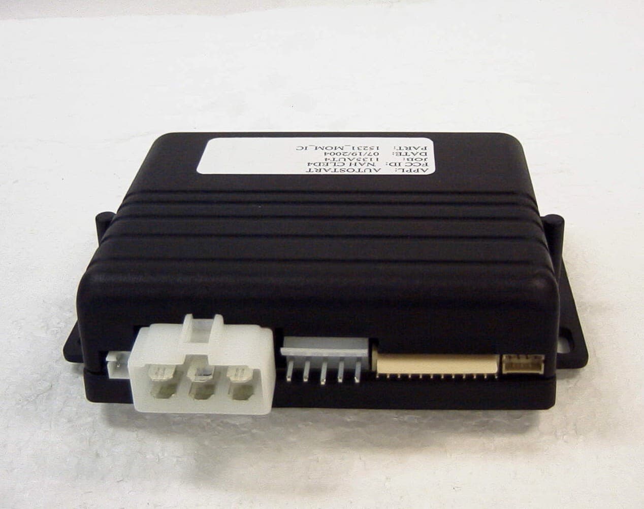
Click to zoom
Application Details
- Equipment Class
- DSC - Part 15 Security/Remote Control Transmitter
- Date of Grant
- Nov 03, 2004
- Application Purpose
- Original Equipment
- Date of Application
- Nov 03, 2004
- Equipment Note
- Security Transceiver - Vehicle Mounted
- Frequency Range
- 433.00000000 - 434.00000000
- Company
- Autostart
- Country
- Canada
Documents & Files
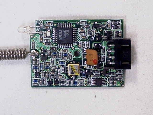
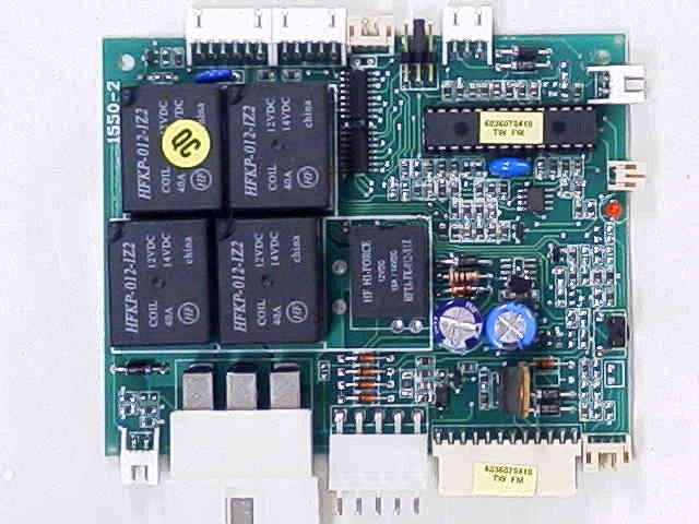
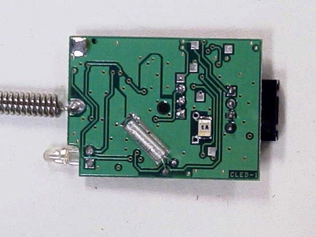
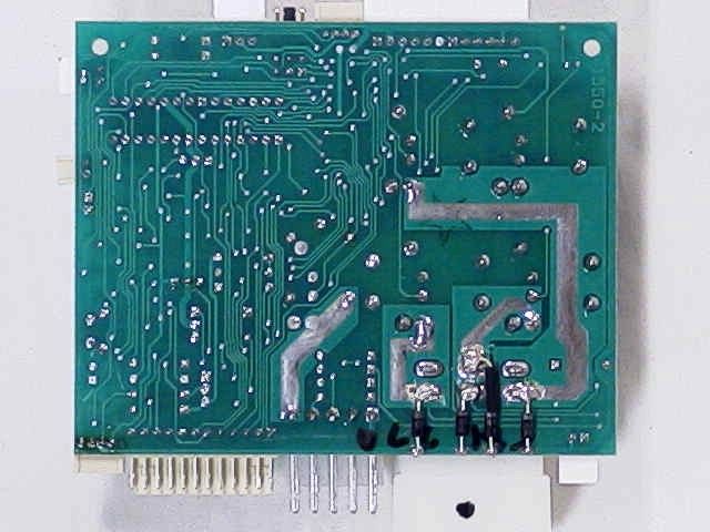
Document Text
Text extracted from the exhibit documents filed with the FCC. Open a document above to read the original.
Users Manual
AUTOMATIC TRANSMISSION REMOTE STARTER AS-2300TW User Guide Table of Contents Table of Contents...................................1 Panic Mode...........................................10 Important Information..............................2 Quick Lockout TM ....................................11 Introduction.............................................2 Cold Weather Mode..............................11 Using the Remote Control......................2 Advanced Features: Installation- programmable Options.........................11 Feature Confirmation Chart....................4 Vehicle Status Request..........................4 Remote Door Locks..............................12 Run Time Status.....................................6 Priority Door Access.............................12 Run Time Cycles....................................7 Active or Passive Arming......................12 Using the Transmitter to Access Features ................................................................7 The Starter Kill and the Anti-grind Feature ..............................................................12 Remote-Starting Your Vehicle................8 Flashing LED........................................12 Remote-starting......................................8 Safe Start..............................................12 Vehicle Presets.......................................8 Home Valet TM .......................................12 Driving Off...............................................8 Ignition-Controlled Door Locks.............13 Using the Remote Starter.......................8 Ignition Re-lock.....................................13 Arming the Starter Kill.............................8 Secure Lock..........................................13 Idle Mode................................................9 Turbo Mode..........................................13 Turbo Mode............................................9 Remote Trunk Release.........................13 Valet Mode..............................................9 Engine Run Time..................................13 Valet Mode Using the Valet Switch.........9 Extended Run Time..............................13 Ignition Valet.........................................10 Multi-car Operation ...............................13 Remote Valet Mode..............................10 Troubleshooting Poor Transmitting Range ..............................................................14 “Home Valet TM ” Mode...........................10 DOC:.1.00 – July 8, 2004 CA LP Manufactured in Canada by Autostart P. 2 User Guide AS-2300TW FCC USER NOTICE (U.S.A.): This device complies with Part 15 of the FCC Rules. Operation is subject to the following two conditions: (1) this device may not cause harmful interference, and (2) this device must accept any interference received, including interference that may cause undesired operation. NOTE: The manufacturer is not responsible for any radio or TV interference caused by unauthorized modifications to this equipment. Such modifications could void the user's authority to operate the equipment. Important Information The boxes below contain information concerning your transmitter and remote starter. We entered the part number of your transmitter for you. Should you need to order a new transmitter, you will need to provide the transmitter part number which is printed below. The second box contains the serial number of the remote starter. Please make sure that the installer has entered the serial number in that box. Transmitter part number: AS-5100TW HHU Car unit: AS-5100TW IVU The installer must use the space below to write the serial number of the remote starter and the location of the valet switch (if installed): Serial number of the remote starter: Location of the valet switch (if installed): Introduction This is a state-of-the-art remote starter system. The system is packed with advanced features such as priority access to the driver’s door (commodity features)and the Safe Start children safety feature. With many an advanced function, this product will satisfy any one your expectations from high-end commodity and security systems, without neglecting any standard feature commonly offered by entry-level starters. Using the Remote Control Your remote starter is equipped with a 5-button multi-channel remote control. It can operate two independent vehicles equipped with a remote starter (see Multi-car operation section on page 13). The functions of the transmitter are as follows: Pressing the SHIFT button and then the LOCK button will activate the AUX 2 output. AS-2300TW Guide d’installation P. 3 P. 4 User Guide AS-2300TW Feature Confirmation Chart Feature LED #1 LED #2 LED #3 LED #4 Beep(s) Lock 3 flashes X X X 1 Unlock X 3 flashes X X 2 Trunk X X 3 flashes X 1 LED ON/OFF 3 flashes 3 flashes X X 1 Start X X X X 1 Running X X X 3 flashes 3 Stop X X X 3 flashes 2 Entering Cold Weather Mode X X X 3 flashes 2 Exiting Cold Weather Mode X X X 3 flashes 1 Home Valet 3 flashes X X 3 flashes 2 Valet Mode 3 flashes X X 3 flashes 1 Exit ValetMode X 3 flashes X 3 flashes 1 Vehicle Status Request The status request feature allows the user to see the status of the vehicle (doors locked or unlocked, vehicle in cold weather mode, vehicle in home valet or vehicle in valet mode). The following chart indicates the confirmations that the user will receive on the transmitter. To retrieve the vehicle status, press and release the SHIFT button then press and release the TRUNK button (there will be a beep). At this point, the transmitter will flash the corresponding sequence of LEDs depending on the vehicle’s status. The status request feature is made up of a two-step transmission: • The first sequence of LED flashes will let you know if the vehicle is locked or unlocked. • The second sequence of LED flashes (if applicable) will let you know if the vehicle is in any of the following statuses: a) Cold weather mode, b) Home valet mode, or c) Valet mode • If there was n…
Text truncated - open the document above for the full version.
Block Diagram
Signal In Details of TH7122's Receiver Receiver of TH7122 7.1505MHz Osc. Antenna RF Switch LNA Receive Date Control Circuit In the Car Transmitter of TH7122 7.1505MHz Amplifier and Maching circuits Transmit Data OSC. X AMP Data Slicer Demodulator Data Out NAHCLED4
Cover Letter(s)
Autostart 5764 Pare Montreal, Quebec H4P 2M2 Tel: (514)738-9750 Fax: (514)738-4365 July 27, 2004 Federal Communications Commission Authorization and Evaluation Division Confidentiality Request regarding application for certification of FCC ID:NAHRLED4 Pursuant to sections 0.457 and 0.459 of the Commission's Rules, we herby request confidential treatment accompanying this application as outlined below: - AS5100TW_HHU_1.pdf (Schematic) The above materials contain trade secrets and proprietary information not customarily released to the public. The public disclosure of these materials may be harmful to the applicant and provide unjustified benefits to its competitors. The applicant understands that pursuant to section 0.457 of the rules, disclosure of this application and all accompanying documentation will not be made before the date of the Grant for this application. Sincerely,
ID Label/Location Info
FCC ID: NAHCLED4 THIS DEVICE COMPLIES WITH PART 15 OF THE FCC RULES. OPERATION IS SUBJECT TO THE FOLLOWING TWO CONDITIONS: (1) THIS DEVICE MAY NOT CAUSE HARMFUL INTERFERENCE, AND (2) THIS DEVICE MUST ACCEPT ANY INTERFERENCE RECEIVED, INCLUDING INTERFERENCE THAT MAY CAUSE UNDESIRED OPERATION.
Operational Description
TECHNICAL DESCRIPTION, AS5100TW-IVU Version 1 SYSTEM DESCRIPTION The AS5100TW-IVU board is used in a half duplex car starter/alarm system and operates at 433.920MHz. The receiver is continuously waiting for a signal from the AS5100TW-HHU Remote Transceiver. The unit can also page the remote transceiver in an alarm system to notify the user of an alarm condition. The AS5100TW-IVU is connected to the car module with a 4-conductor cable. The transceiver is powered from the car module (+5 volts). 1 pin is used for both Tx and Rx data, 2 pins are used for GND and +5 volts, and the last pin is used for LED control. During transmit, 5 volts is applied to the transmit section via a transistor switch. System timing and control is done by 2 microprocessors, 1 in the car, and 1 in the remote. CIRCUIT DESCRIPTION Receiver Section The receiver is a WBFM single conversion super-het design with an Image BPF. The signal enters via CON 1 and forwarded to LPF C2, L1. MMIC RF switch S1 forwards the 433.920MHz signal to a matched cascade amplifier Q1, Q2. SAW filter FL1, provides image rejection and protection from strong out of band signals. The output of FL1 is then matched to U2 by L7 and C15, U2 is a complete MMIC receiver. This IC contains a PLL frequency synthesizer, an IF amplifier and FM demodulator. It is based on the principle of a single conversion superhet. The 433.920MHz signal is down converted to a 10.7MHz IF. The IF signal is band-pass filtered by a ceramic filter (FL2) and then amplified, and demodulated by an FM detector. The baseband signal is forwarded to U3B, pin 5. (+ input) U3B pin 7 outputs signal to J2 pin 2. Transmitter Section The transmitter is provided by U2. The output is matched to Q3, and matched to 50 ohms by C11, L6, C10, C12. S1 forwardes signal to the antenna. The WBFM modulation is accomplished by the internal diode switch in U2. (Pin 11) Baseband Diplexer U3A and U3B provide the bi-directional function for the Tx and Rx path. A data signal above 4.V peak will provide output at U3 pin 1. This output goes to RC time constant R29, C37 to turn ON Q4, Q5. With Q4 collector high, D3 holds U3B pin 7 high. Receive signals are held to 3.3V peak and will not trigger U3B. The threshold for U3A is 3.0V. D5 povided input transient protection. U1 is a 3.3V regulator to power the board. AS5100TW-IVU 07/16/04 ISSUE 2.00 INTERNAL CIRCUIT VOLTAGES A reference schematic is provided for in circuit voltages. These voltages are provided to help trouble-shoot defective circuit boards. The values may vary ±10%. AS5100TW-IVU TRANSCEIVER SPECIFICATION TRANSCEIVER BOARD RECEIVE SECTION Design Requirement Actual Receiver Frequency 433.920 MHz √ Receiver Sensitivity -111 dBm minTyp –113 dBm 6dB IF Bandwidth 180 KHz min √ Image Response -40dBc minTyp -45dBc LO feedthrough at Antenna Input -60 dBm max-70 dBm Receive Data Rate 1 Kbit/sec max √ Pulse distortion 66/33% duty cycle <10%<5% Modulation WBFM ±25KHzNominal √ Rx Data Out 0 to 3.15V min √ Rec. Offset Frequency Acceptance for 3 dB degrad. of Sensitivity ± 32KHz √ J2 Pin 1 Input Voltage (neg. Gnd.) +5 V ± .25 V √ Current Consumption (Rx) 13 mA max √ P1dB (ref. to input) -25 dBm √ Temperature range -30°C to +60°C √ Humidity 100% conden. @ 0°C √ TRANSMIT SECTION Transmitter Frequency 433.920 MHz √ Output Power 12,000 uV/M @ 3M √ Transmitter Spurious Output 1200 uV/M @3MTyp –40 dBc Data Rate Transmit (Manchester Encoded) 1.56Kbit/sec max √ Tx Modulator Input 0 to +4.8 volts Square Wave √ Frequency Deviation ± 22 KHz typ. 15 Min, 30Max. Current Consumption (Tx) 30 mA max √ Frequency tolerance ±32 KHz Max Over Temp. √ Temperature range -30°C to +60°C √ Humidity 100% conden. @ 0°C √ AS5100TW-IVU 07/16/04 ISSUE 2.00 POWER INTERFACE CONNECTIONS (0.098 Pin Spacing) 1 + 5 Volts 2 Tx/Rx Data 3 Ground 4 LED AS5100TW-IVU 07/16/04 ISSUE 2.00
Test Report
TIMCO ENGINEERING INC. 849 NW State Road 45 Newberry, Florida 32669 http://www.timcoengr.com 888.472.2424 F 352.472.2030 email: [email protected] APPLICANT: AUTOSTART FCC ID: NAHCLED4 REPORT #: A\AUTONAH\1135YUT4\1135YUT4TestReport.doc COVER SHEET Test Report Product Name: SECURITY TRANSCEIVER –VEHICLE MOUNTED FCC ID: NAHCLED4 Applicant: AUTOSTART 5764 PARE MONTREAL QUEBEC H4P 2M2 CANADA Date Receipt: OCTOBER 1, 2004 Date Tested: OCTOBER 8, 2004 TIMCO ENGINEERING INC. 849 NW State Road 45 Newberry, Florida 32669 http://www.timcoengr.com 888.472.2424 F 352.472.2030 email: [email protected] APPLICANT: AUTOSTART FCC ID: NAHCLED4 REPORT #: A\AUTONAH\1135YUT4\1135YUT4TestReport.doc TABLE OF CONTENTS APPLICANT: AUTOSTART FCC ID: NAHCLED4 TABLE OF CONTENTS TEST REPORT CONTAINING: PAGE 1.............TEST EQUIPMENT LIST PAGE 2.............TEST PROCEDURE PAGE 3.............RADIATION INTERFERENCE TEST DATA PAGE 4.............CALCULATION OF DUTY CYCLE PAGE 5.............DUTY CYCLE PLOT PAGE 6.............OCCUPIED BANDWIDTH PAGE 7.............OCCUPIED BANDWIDTH PLOT EXHIBIT INCLUDING: CONFIDENTIALITY REQUEST LETTER BLOCK DIAGRAM SCHEMATIC PARTS LIST INSTRUCTION MANUAL LABEL SAMPLE LABEL LOCATION EXTERNAL PHOTOGRAPHS INTERNAL PHOTOGRAPHS OPERATIONAL DESCRIPTION TEST SET UP PHOTOGRAPH TIMCO ENGINEERING INC. 849 NW State Road 45 Newberry, Florida 32669 http://www.timcoengr.com 888.472.2424 F 352.472.2030 email: [email protected] APPLICANT: AUTOSTART FCC ID: NAHCLED4 REPORT #: A\AUTONAH\1135YUT4\1135YUT4TestReport.doc Page 1 of 7 EMC Equipment List Device Manufacturer Model Serial Number Cal/Char Date Due Date 3/10-Meter OATS TEI N/A N/A Listed 3/27/04 3/26/07 3-Meter OATS TEI N/A N/A Listed 1/13/03 1/12/06 Biconnical Antenna Eaton 94455-1 1057 CAL 3/18/03 3/18/05 Biconnical Antenna Eaton 94455-1 1096 CAL 8/17/04 8/17/06 Biconnical Antenna Electro- Metrics BIA-25 1171 CAL 4/26/01 4/26/03 Blue Tower Quasi-Peak Adapter HP 85650A 2811A01279 CAL 4/15/03 4/15/05 Blue Tower RF Preselector HP 85685A 2620A00294 CAL 4/27/04 4/27/06 Blue Tower Spectrum Analyzer HP 8568B 2928A04729 2848A18049 CAL 4/15/03 4/15/05 Double- Ridged Horn Antenna Electro- Metrics RGA-180 2319 CAL 2/17/03 2/17/05 LISN Electro- Metrics ANS-25/2 2604 CAL 8/27/04 8/27/06 LISN Electro- Metrics EM-7820 2682 CAL 3/12/03 3/12/05 Log- Periodic Antenna Eaton 96005 1243 CAL 5/8/03 5/8/05 TIMCO ENGINEERING INC. 849 NW State Road 45 Newberry, Florida 32669 http://www.timcoengr.com 888.472.2424 F 352.472.2030 email: [email protected] APPLICANT: AUTOSTART FCC ID: NAHCLED4 REPORT #: A\AUTONAH\1135YUT4\1135YUT4TestReport.doc Page 2 of 7 TEST PROCEDURE GENERAL: This report shall NOT be reproduced except in full without the written approval of TIMCO ENGINEERING, INC. RADIATION INTERFERENCE: The test procedure used was ANSI STANDARD C63.4-1992 using a HEWLETT PACKARD spectrum analyzer with a pre-selector. The bandwidth of the spectrum analyzer was 100 kHz with an appropriate sweep speed. The analyzer was calibrated in dB above a microvolt at the output of the antenna. The resolution bandwidth was 100KHz and the video bandwidth was 300KHz. The ambient temperature of the UUT was 98.3ºF with a humidity of 40%. FORMULA OF CONVERSION FACTORS: The Field Strength at 3m was established by adding the meter reading of the spectrum analyzer (which is set to read in units of dBuV) to the antenna correction factor supplied by the antenna manufacturer. The antenna correction factors are stated in terms of dB. The gain of the Preselector was accounted for in the Spectrum Analyzer Meter Reading. Example: Freq (MHz) METER READING + ACF = FS 33 20 dBuV + 10.36 dB = 30.36 dBuV/m @ 3m ANSI STANDARD C63.4-1992 10.1.7 MEASUREMENT PROCEDURES: The UUT was placed on a table 80 cm high and with dimensions of 1m by 1.5m. The UUT was placed in the center of the table. The table used for radiated measurements is capable of continuous rotation. The spectrum was scanned from 30 MHz to 10th harmonic of the fundamental. Peak readings were taken in three (3) orthogonal planes and the highest readings were converted to average readings based on the duration of "ON" time. When an emission was found, the table was rotated to produce the maximum signal strength. At this point, the antenna was raised and lowered from 1m to 4m. The antenna was placed in both the horizontal and vertical planes. Measurements were made by TIMCO ENGINEERING INC. at the registered open field test site located at 849 N.W. State Road 45, Newberry, Fl 32669. TIMCO ENGINEERING INC. 849 NW State Road 45 Newberry, Florida 32669 http://www.timcoengr.com 888.472.2424 F 352.472.2030 email: [email protected] APPLICANT: AUTOSTART FCC ID: NAHCLED4 REPORT #: A\AUTONAH\1135YUT4\1135YUT4TestReport.doc Page 3 of 7 APPLICANT: AUTOSTART FCC ID: NAHCLED4 NAME OF TEST: RADIATION INTERFERENCE RULES PART NO.: 15.231 REQUIREMENTS: Fundamental Field Strength Field Strength of Frequency of Fundamental Harmonics and Spurious MHz dBuV Emissions (dBuV/m @ 3m) 40.66 to 40.70 67.04 47.04 70 to 130 61.94 41.94 130 to 174 61.94 to 71.48 41.94 to 51.48 174 to 260 71.48 51.48 260 to 470 71.48 to 81.94 51.48 to 61.94 470 and above 81.94 61.94 THE LIMIT FOR AVERAGE FIELD STRENGTH dBuV/m FOR THE FUNDAMENTAL FREQUENCY = 80.82 dBuV/m. NO FUNDAMENTAL IS ALLOWED IN THE RESTRICTED BANDS. THE LIMIT FOR AVERAGE FIELD STRENGTH dBuV/m FOR THE HARMONICS AND SPURIOUS FREQUENCIES = 60.82 dBuV/m. SPURIOUS IN THE RESTRICTED BANDS MUST BE LESS THAN 54 dBuV/m OR 15.209. TEST DATA: Tuned Frequency MHz Emission Frequency MHz * Meter Reading dBuV Ant. Polarity Coax Loss dB Correction Factor dB Duty Cycle Factor dB Field Strength dBuV/m Margin dB 433.9 433.90 56.5 V 1.23 16.28 0.00 74.01 6.81 433.9 433.90 59.9 H 1.23 16.70 0.00 77.83 2.99 433.9 867.80 12.2 V 1.93 22.22 0.00 36.35 24.47 433.9 867.80 14.1 H 1.93 22.90 0.00 38.93 21.89 433.9 1,301.90 ** 18.4 H 2.34 26.23 0.00 46.97 7.03 433.9 1,301.90 ** 19.0 V 2.34 26.23 0.00 47.57 6.43 433.9 1,735.80 20.0 V 2.69 27.75 0.00 50…
Text truncated - open the document above for the full version.
Contact Information
Applicant
Jack Wisnia(President)
Test Firm
Timco Engineering, Inc.S Sanders
Technical Specifications
| # | Rule Parts | Frequency Range | Power Output |
|---|---|---|---|
| 1 | 15.231 | 433 MHz - 434 MHz | - |
Other Applications from Autostart
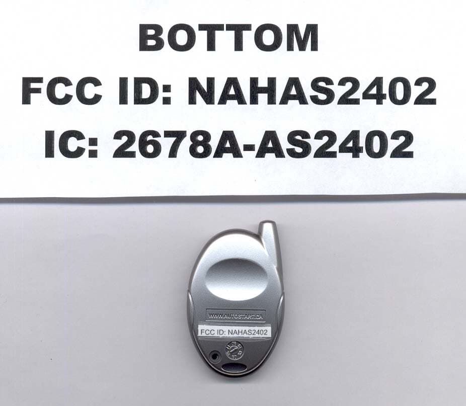
NAHAS2402
Jun 19, 20074 BUTTON OOK REMOTE
Equipment Class
DSC - Part 15 Security/Remote Control Transmitter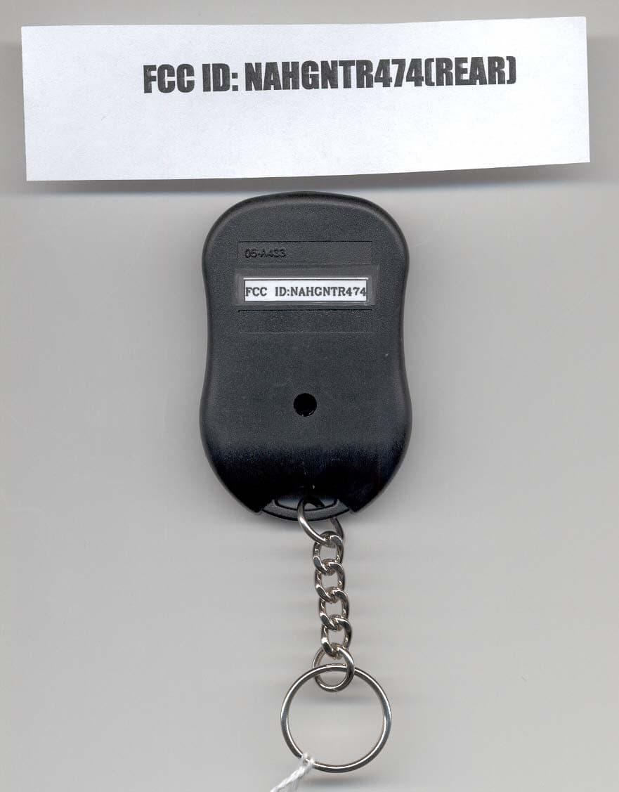
NAHGNTR474
Feb 14, 2007DECURITY TRANSMITTER
Equipment Class
DSC - Part 15 Security/Remote Control Transmitter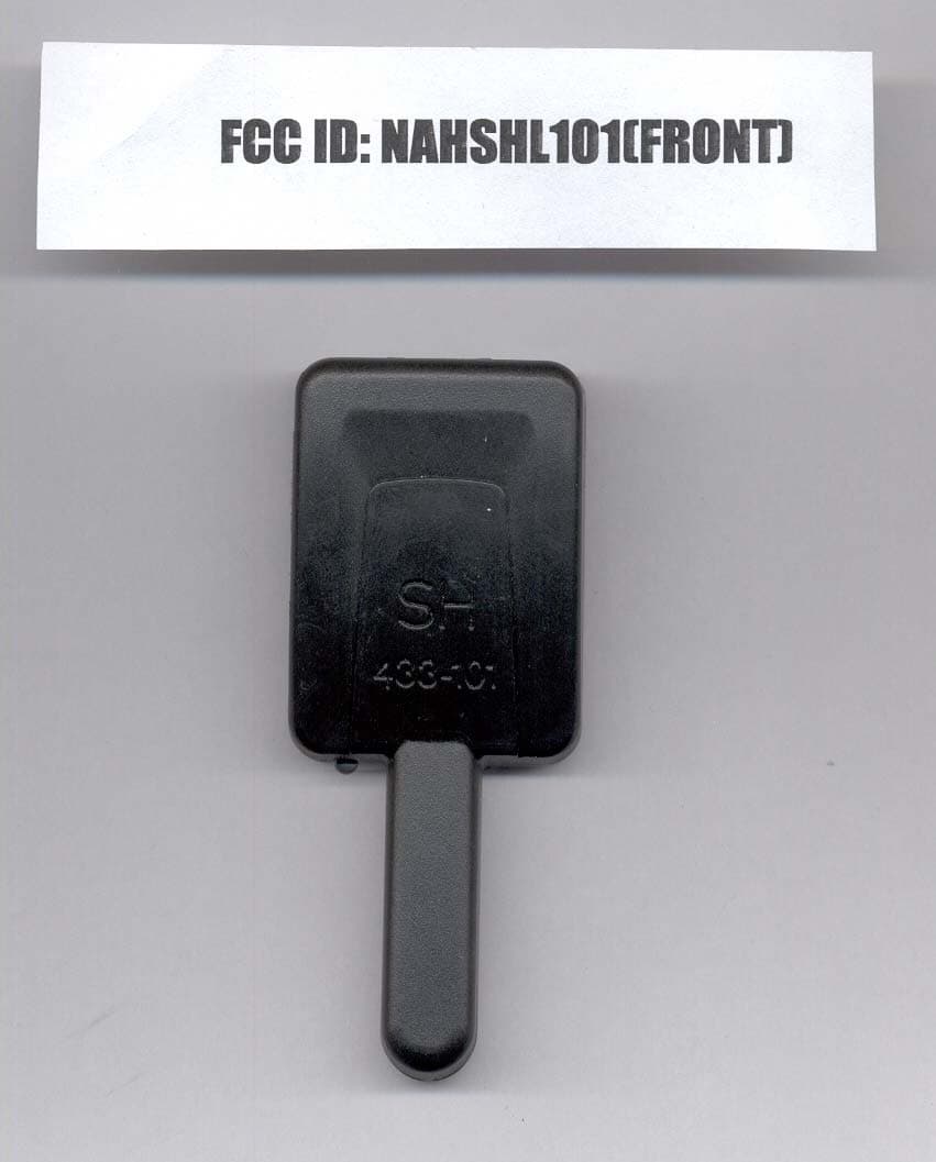
NAHSHL101
Feb 14, 2007SECURITY RECEIVER
Equipment Class
CYY - Communications Receiver used w/Pt 15 Transmitter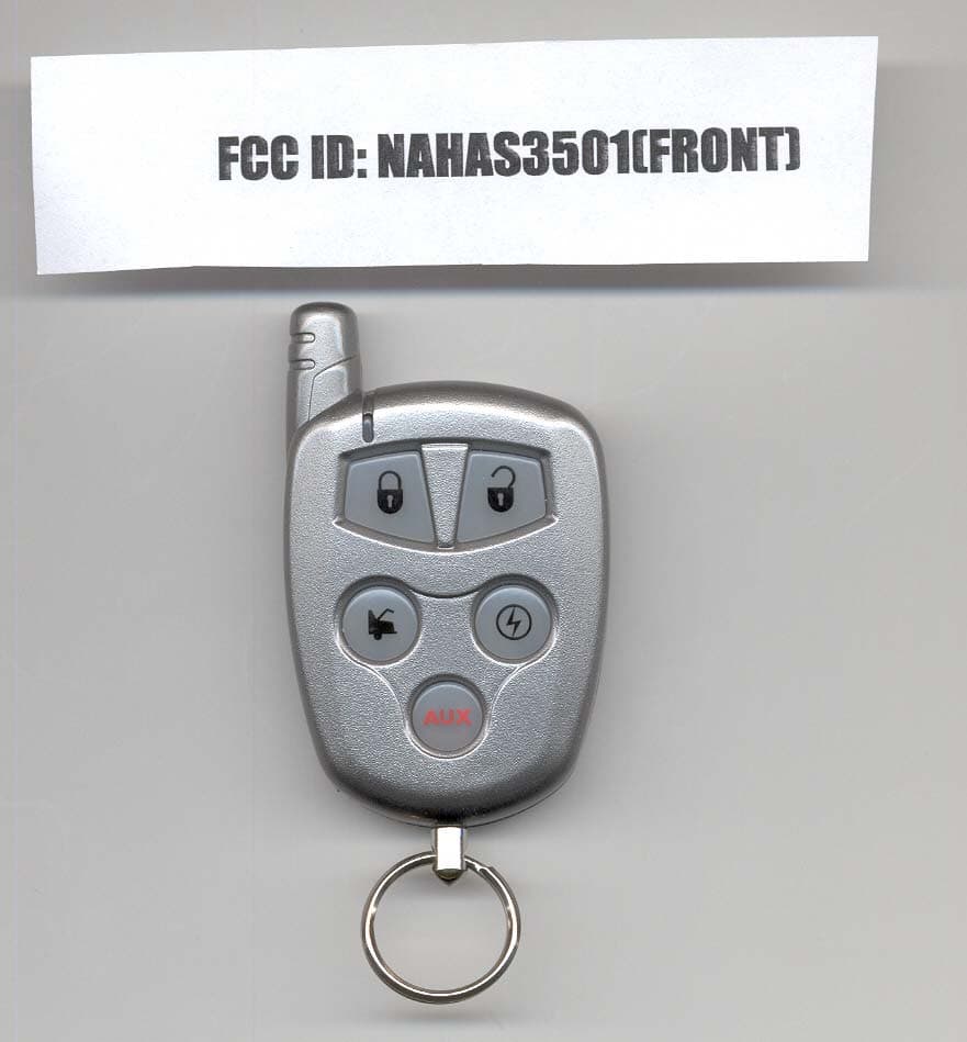
NAHAS3501
Jan 24, 2007SECURITY TRANSMITTER
Equipment Class
DSC - Part 15 Security/Remote Control Transmitter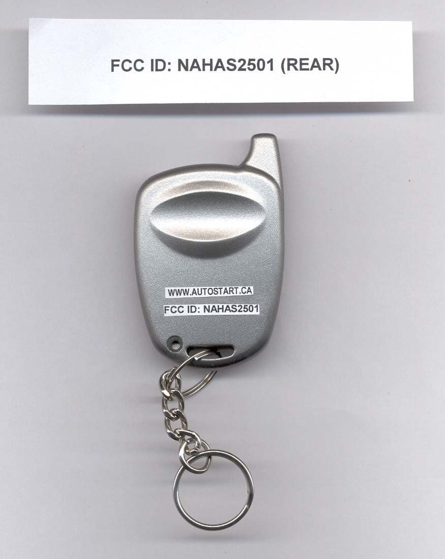
NAHAS2501
Sep 25, 2006REMOTE CONTROL TRANSMITTER
Equipment Class
DSC - Part 15 Security/Remote Control Transmitter