NAHSAW4SECURITY TRANSMITTER
AutostartApplication Details
- Equipment Class
- DSC - Part 15 Security/Remote Control Transmitter
- Date of Grant
- Nov 03, 2003
- Application Purpose
- Original Equipment
- Date of Application
- Nov 03, 2003
- Equipment Note
- SECURITY TRANSMITTER
- Frequency Range
- 433.00000000 - 434.00000000
- Company
- Autostart
- Country
- Canada
Documents & Files
Document Text
Text extracted from the exhibit documents filed with the FCC. Open a document above to read the original.
Users Manual
AUTOMATIC TRANSMISSION MULTI CHANNEL REMOTE STARTER SYSTEM AS-1525 SH User Guide Transmitter Part Number and Module Serial Number............................................................2 Introduction......................................................2 Basic Remote Operation..................................2 Remote-starting Your Vehicle..........................3 Vehicle Presets...........................................3 Driving Off...................................................3 Advanced Features..........................................3 Idle Mode....................................................3 Valet Mode..................................................4 Ignition Valet...............................................4 “Home Valet” TM Mode.................................4 Panic Mode.................................................5 Quick Lockout TM ..........................................5 Cold Weather Mode....................................5 Remote Door Locks....................................5 Priority Door Access...................................6 Arming the Starter Kill.................................6 Installation-programmable Options..................6 Remote Door Locks Option.........................6 Safe Start.....................................................6 Starter Kill / Anti-grind feature.....................7 Active / Passive Arming of the Starter Kill...7 Idle Mode Option.........................................7 Ignition-controlled Door Locks Option.........7 Smart Ignition Locks Option........................7 Secure Lock Option.....................................7 Priority Door Access Option........................7 Horn Confirmation Option............................8 Engine Run Time.........................................8 Key Sense Option........................................8 The AUX 1, AUX 2 and AUX 3 Outputs......8 Multi-car Operation......................................8 Troubleshooting Poor Transmitting Range......8 Diagnostics – Parking Lights Flash Rate (Normal Operation).................................10 FCC USER NOTICE (U.S.A.): This device complies with Part 15 of the FCC Rules. Operation is subject to the following two conditions: (1) this device may not cause harmful interference, and (2) this device must accept any interference received, including interference that may cause undesired operation. NOTE: The manufacturer is not responsible for any radio or TV interference caused by unauthorized modifications to this equipment. Such modifications could void the user's authority to operate the equipment. H.2.40 S.3.00 Rev: YxW\ – October 16, 2003 Fb CA Manufactured in Canada by Autostart Transmitter Part Number and Module Serial Number Transmitter Part Number: ASTR-575CF The installer is to write in the boxes below the Module’s serial number and the location of the Valet Switch. Module Serial Number: Valet Switch is located: Introduction This Module is a state-of-the-art remote car starter system. The system is packed with advanced features such as priority access to the driver’s door and the Safe Start children safety feature. Among other sophistications, it features super-heterodyne transmission technology for increased range of operation. With many an advanced function, this product will satisfy any one of the user’s expectations from high-end commodity systems, without neglecting any standard feature commonly offered by entry-level starters. Basic Remote Operation Your system is equipped with a multi-channel 5-button remote transmitter. It can operate two independent identically-equipped vehicles (see Multi-car Operation for 2 nd car functions). P. 2 User Guide AS-1525 SH Note: Pressing the LOCK and UNLOCK buttons at the same time will activate the AUX2 output. Remote-starting Your Vehicle Press the START button for approx. 1 second. The parking lights will come ON, informing you that the unit has received your signal. The engine will start approximately 5 seconds later. The parking lights will remain on during the entire pre-programmed engine run time. If the vehicle doesn’t start the first time, the system will shut off, wait a few seconds and try to start the engine again. It will make three start attempts before giving up. Vehicle Presets Heater and Heated Seat: When leaving the vehicle it is recommended to preset the accessory controls in preparation for the next remote start. Settings for the blower motor (fan), front and rear, as well as heated seats (if equipped) should not be left on HIGH. It is recommended to leave the settings on LOW or MEDIUM instead. Windshield Wipers, Radio and Headlights: Certain vehicles require the radio and / or windshield wiper and / or headlight circuits to become energized while running under remote start. When leaving the vehicle you must ensure that the windshield wiper and headlight switches are OFF. Leaving the headlight switch ON on certain types of vehicles could cause them to remain ON even after remote starter shut down, resulting in a dead battery. Driving Off With the vehicle running under remote control, press the UNLOCK button to disarm the system (and unlock the doors if keyless entry is installed). Enter the vehicle and do the following: 1. Turn the ignition key to the IGNITION ON (RUN) position. 2. Press the brake pedal to disengage the remote starter unit. You are now ready to drive off. Caution! Upon entering your vehicle after it has been remote-started, do not turn the key to the CRANK position while the engine is running. This would cause the starter motor to re- engage, unless the anti-grind feature is installed. Advanced Features Idle Mode This feature allows you to remove the ignition key from the ignition switch and leave the vehicle running without the key while you are away from your vehicle, until the pre-programmed engine run time expires or until it the vehicle is shut down with the remote control. This feature may be handy if you need to make a short stop…
Text truncated - open the document above for the full version.
Operational Description
ASTR575 9/30/03 ISSUE 1.00 TECHNICAL DESCRIPTION, ASTR575 SYSTEM DESCRIPTION, ASTR575, ASTR575CF The ASTR575 Remote Transmitter is used in a Car Starter/Alarm System and operates at 433.920MHz, OOK. 5 Buttons The transmit code uses 25 bits 1 start bit, 16 ID bits and 8 bits for button ID information. Bit length is 500/1000uSec. CIRCUIT DESCRIPTION Transmitter Section The transmitter is provided a single transistor SAW stabilised oscillator Q1. C3, C4 provide the necessary feedback for the Colpitts SAW oscillator. U1, an intergated CMOS IC, provides system timing and a serial bit stream to OOK modulate the oscillator. The loop antena is resonate to 433.920MHz. D2,3,4 combine each botton to power U1 . D1 , an LED is lit by the current through Q1. The Remote is powered by 1, 12 Volt battery. ASTR575 TRANSMITTER SPECIFICATION TRANSMITTER Transmitter Frequency 433.920 MHz √ Frequency Tolerance @ 25°C ± 100KHz √ Output Power (Radiated from Case) 12000 uV/meter max. √ Transmitter Spurious Output 1200 uV/meter max. √ Data Rate Transmit (Nutek Code) 1.0Kbit/sec max. √ Voltage Range 8.0Vmin to 12.5V max. √ Current Consumption (Tx only) 3.0 mA max. √ Temperature range -20°C to +50°C √ Humidity 100% conden. @ 0°C √
Test Report
APPLICANT: AUTOSTART FCC ID: NAHSAW4 REPORT #: A\AUTONAH\1283UT3\1283UT3TestReport.doc TABLE OF CONTENTS LIST TABLE OF CONTENTS APPLICANT: AUTOSTART FCC ID: NAHSAW4 TEST REPORT CONTAINING: PAGE 1.............TEST EQUIPMENT LIST PAGE 2.............TEST PROCEDURE PAGE 3-4...........RADIATION INTERFERENCE TEST DATA PAGE 5.............CALCULATION OF DUTY CYCLE PAGE 6-9...........DUTY CYCLE PLOTS PAGE 10............OCCUPIED BANDWIDTH PAGE 11............OCCUPIED BANDWIDTH PLOT EXHIBIT ATTACHMENTS: EXHIBIT 1...........BLOCK DIAGRAM EXHIBIT 2...........SCHEMATIC EXHIBIT 3...........INSTRUCTION MANUAL EXHIBIT 4...........LABEL SAMPLE EXHIBIT 5...........LABEL LOCATION EXHIBIT 6...........EXTERNAL PHOTOGRAPHS EXHIBIT 7...........INTERNAL PHOTOGRAPHS EXHIBIT 8...........CIRCUIT DESCRIPTION EXHIBIT 9...........TEST SET UP PHOTOGRAPH EXHIBIT 10..........CONFIDENTIALITY LETTER APPLICANT: AUTOSTART FCC ID: NAHSAW4 REPORT #: A\AUTONAH\1283UT3\1283UT3TestReport.doc Page 1 of 11 EMC Equipment List Device Manufacturer Model Serial Number Cal/Char Date Due Date 3/10-Meter OATS TEI N/A N/A Listed 3/26/01 3/26/04 3-Meter OATS TEI N/A N/A Listed 1/13/03 1/13/06 Biconnical Antenna Eaton 94455-1 1057 CAL 3/18/03 3/18/05 Biconnical Antenna Eaton 94455-1 1096 CAL 10/1/01 10/1/03 Biconnical Antenna Electro- Metrics BIA-25 1171 CAL 4/26/01 4/26/03 Blue Tower Quasi-Peak Adapter HP 85650A 2811A01279 CAL 4/15/03 4/15/05 Blue Tower RF Preselector HP 85685A 2926A00983 CAL 4/15/03 4/15/05 Blue Tower Spectrum Analyzer HP 8568B 2928A04729 2848A18049 CAL 4/15/03 4/15/05 Double-Ridged Horn Antenna Electro- Metrics RGA-180 2319 CAL 2/17/03 2/17/05 LISN Electro- Metrics ANS-25/2 2604 CAL 10/9/01 10/9/03 LISN Electro- Metrics EM-7820 2682 CAL 3/12/03 3/12/05 Log-Periodic Antenna Eaton 96005 1243 CAL 5/8/03 5/8/05 Log-Periodic Antenna Electro- Metrics EM-6950 632 CHAR 10/15/01 10/15/03 Log-Periodic Antenna Electro- Metrics LPA-25 1122 CAL 10/2/01 10/2/03 Log-Periodic Antenna Electro- Metrics LPA-30 409 CAL 3/4/03 3/4/05 Oscilloscope Tektronix 2230 300572 CAL 7/3/03 7/3/05 Silver Tower Preamplifier HP 8449B 3008A01075 CHAR 1/28/02 1/28/04 Silver Tower Quasi-Peak Adapter HP 85650A 3303A01844 CAL 10/14/02 10/14/04 Silver Tower RF Preselector HP 85685A 2620A00294 CAL 10/14/02 10/14/04 Silver Tower Spectrum Analyzer HP 8566B Opt 462 3552A22064 3638A08608 CAL 10/14/02 10/14/04 Tan Tower Preamplifier HP 8449B-H02 3008A00372 CHAR 3/4/01 3/4/03 Tan Tower Quasi-Peak Adapter HP 85650A 3303A01690 CAL 8/31/01 8/31/03 Tan Tower RF Preselector HP 85685A 3221A01400 CAL 8/31/01 8/31/03 Tan Tower Spectrum Analyzer HP 8566B Opt 462 3138A07786 3144A20661 CAL 8/31/01 8/31/03 APPLICANT: AUTOSTART FCC ID: NAHSAW4 REPORT #: A\AUTONAH\1283UT3\1283UT3TestReport.doc Page 2 of 11 TEST PROCEDURE GENERAL: This report shall NOT be reproduced except in full without the written approval of TIMCO ENGINEERING, INC. RADIATION INTERFERENCE: The test procedure used was ANSI STANDARD C63.4-1992 using a HEWLETT PACKARD spectrum analyzer with a pre-selector. The bandwidth of the spectrum analyzer was 100 kHz with an appropriate sweep speed. The analyzer was calibrated in dB above a microvolt at the output of the antenna. The resolution bandwidth was 100KHz and the video bandwidth was 300KHz. The ambient temperature of the UUT was 98.3ºF with a humidity of 40%. FORMULA OF CONVERSION FACTORS: The Field Strength at 3m was established by adding the meter reading of the spectrum analyzer (which is set to read in units of dBuV) to the antenna correction factor supplied by the antenna manufacturer. The antenna correction factors are stated in terms of dB. The gain of the Pre- selector was accounted for in the Spectrum Analyzer Meter Reading. Example: Freq (MHz) METER READING + ACF = FS 33 20 dBuV + 10.36 dB = 30.36 dBuV/m @ 3m ANSI STANDARD C63.4-1992 10.1.7 MEASUREMENT PROCEDURES: The UUT was placed on a table 80 cm high and with dimensions of 1m by 1.5m. The UUT was placed in the center of the table. The table used for radiated measurements is capable of continuous rotation. The spectrum was scanned from 30 MHz to 10th harmonic of the fundamental. Peak readings were taken in three (3) orthogonal planes and the highest readings were converted to average readings based on the duration of "ON" time. When an emission was found, the table was rotated to produce the maximum signal strength. At this point, the antenna was raised and lowered from 1m to 4m. The antenna was placed in both the horizontal and vertical planes. Measurements were made by TIMCO ENGINEERING INC. at the registered open field test site located at 849 N.W. State Road 45, Newberry, Fl 32669. APPLICANT: AUTOSTART FCC ID: NAHSAW4 REPORT #: A\AUTONAH\1283UT3\1283UT3TestReport.doc Page 3 of 11 APPLICANT: AUTOSTART FCC ID: NAHSAW4 NAME OF TEST: RADIATION INTERFERENCE RULES PART NO.: 15.231 REQUIREMENTS: Fundamental Field Strength Field Strength of Frequency of Fundamental Harmonics and Spurious MHz dBuV Emissions (dBuV/m @ 3m) 40.66 to 40.70 67.04 47.04 70 to 130 61.94 41.94 130 to 174 61.94 to 71.48 41.94 to 51.48 174 to 260 71.48 51.48 260 to 470 71.48 to 81.94 51.48 to 61.94 470 and above 81.94 61.94 THE LIMIT FOR AVERAGE FIELD STRENGTH dBuV/m FOR THE FUNDAMENTAL FREQUENCY= 80.82 dBuV/m. NO FUNDAMENTAL IS ALLOWED IN THE RESTRICTED BANDS. THE LIMIT FOR AVERAGE FIELD STRENGTH dBuV/m FOR THE HARMONICS AND SPURIOUS FREQUENCIES = 60.82 dBuV/m. SPURIOUS IN THE RESTRICTED BANDS MUST BE LESS THAN 54dBuV/m OR 15.209. TEST DATA: Emission Frequency MHz Meter Reading dBuV Ant. Polarity Coax Loss dB Correction Factor dB Duty Cycle Factor dB Field Strength dBuV/m Margin dB PHASE 1 433.92 66.4 V 2.90 16.42 16.09 69.63 11.19 433.92 59.7 H 2.90 17.00 16.09 63.51 17.31 867.84 34.0 V 4.14 22.14 16.09 44.19 16.64 867.84 29.2 H 4.14 22.86 16.09 40.11 20.72 1,301.76 ** 41.9 V 1.35 26.23 16.09 53.39 0.61 1,301.76 ** 29.7 H 1.35 26.23 16.09 41.19 12.81 1,735.68 34.2 V 1.57 27.75 16.09 47.43 13.40 1,735.68 26.8 H 1.57 27.70 16.09 39.98 20…
Text truncated - open the document above for the full version.
Contact Information
Applicant
Jack Wisnia(President)
Test Firm
Timco Engineering, Inc.S Sanders
Technical Specifications
| # | Rule Parts | Frequency Range | Power Output |
|---|---|---|---|
| 1 | 15.231 | 433 MHz - 434 MHz | - |
Other Applications from Autostart
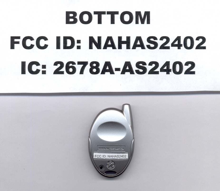
NAHAS2402
Jun 19, 20074 BUTTON OOK REMOTE
Equipment Class
DSC - Part 15 Security/Remote Control Transmitter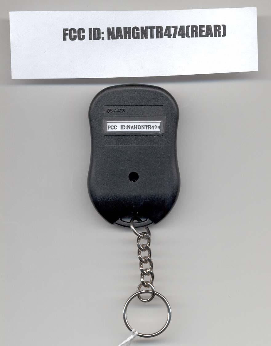
NAHGNTR474
Feb 14, 2007DECURITY TRANSMITTER
Equipment Class
DSC - Part 15 Security/Remote Control Transmitter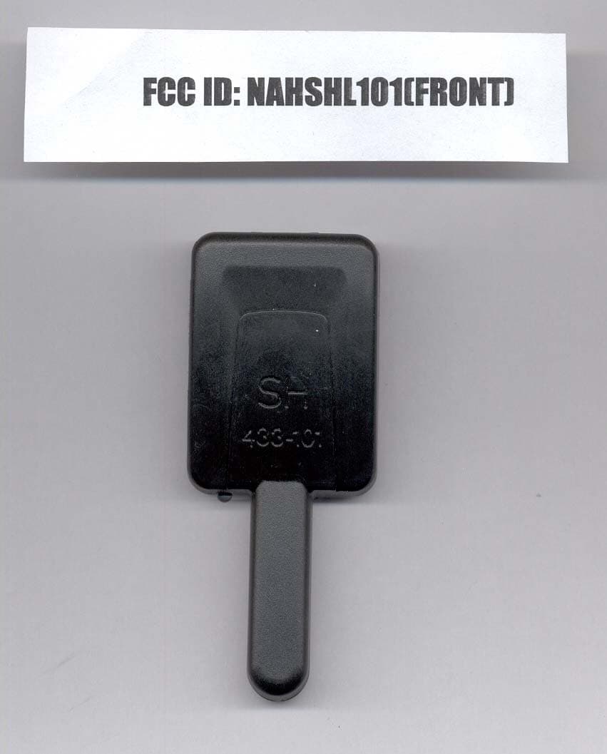
NAHSHL101
Feb 14, 2007SECURITY RECEIVER
Equipment Class
CYY - Communications Receiver used w/Pt 15 Transmitter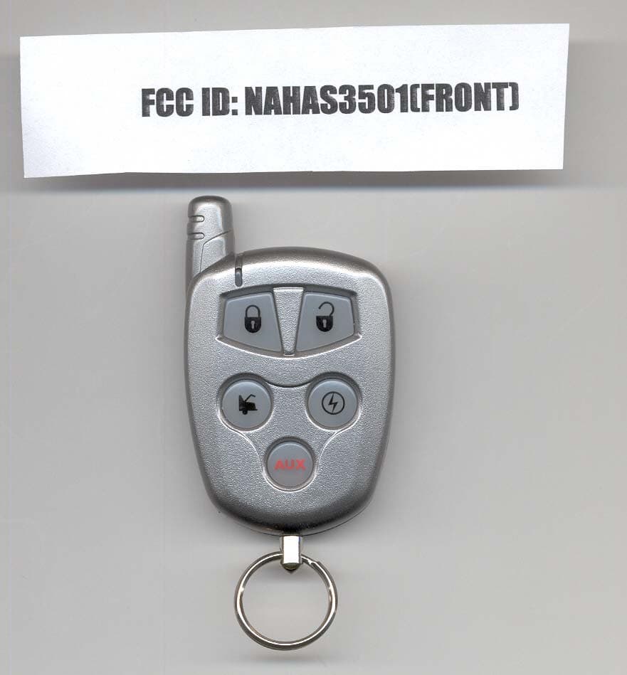
NAHAS3501
Jan 24, 2007SECURITY TRANSMITTER
Equipment Class
DSC - Part 15 Security/Remote Control Transmitter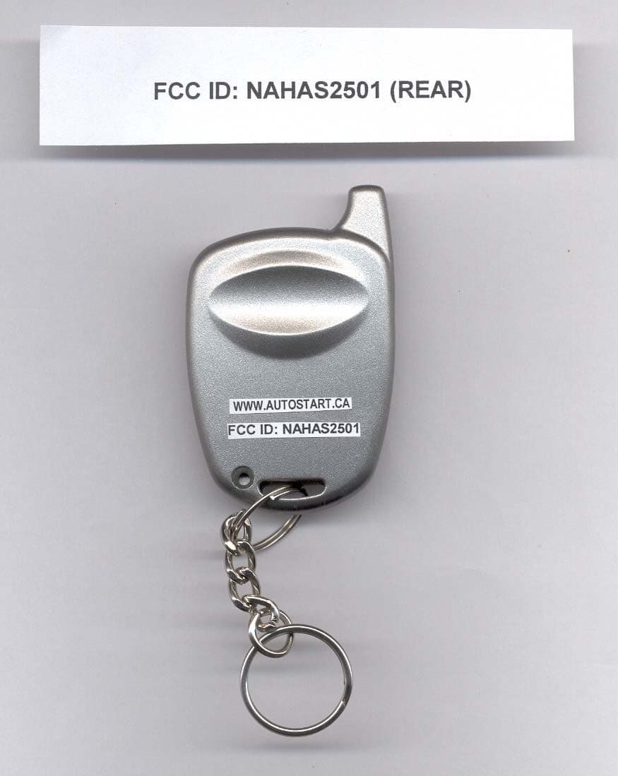
NAHAS2501
Sep 25, 2006REMOTE CONTROL TRANSMITTER
Equipment Class
DSC - Part 15 Security/Remote Control Transmitter