NAHTDK4REMOTE CONTROL TRANSMITTER
Autostart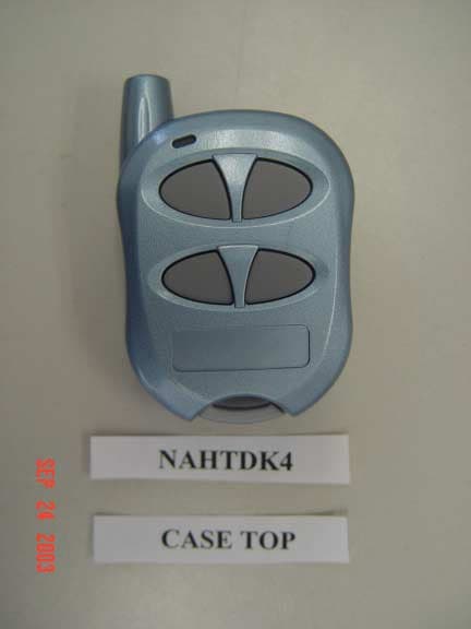
Click to zoom
Application Details
- Equipment Class
- DSC - Part 15 Security/Remote Control Transmitter
- Date of Grant
- Oct 20, 2003
- Application Purpose
- Original Equipment
- Date of Application
- Oct 20, 2003
- Equipment Note
- REMOTE CONTROL TRANSMITTER
- Frequency Range
- 433.00000000 - 434.00000000
- Company
- Autostart
- Country
- Canada
Documents & Files
Document Text
Text extracted from the exhibit documents filed with the FCC. Open a document above to read the original.
Users Manual
AUTOMATIC TRANSMISSION MULTI-CHANNEL TWO-WAY LCD REMOTE STARTER SYSTEM AS-2510 TW User Guide Transmitter Part Number and Module Serial Number.......................................................2 Introduction.................................................2 What is “eSH” Technology?........................2 Basic Remote Operation............................2 LCD Remote Functions..............................3 Basic Vehicle Operation.............................3 Alarm Clock................................................4 Time Adjust Mode.......................................4 Countdown Timer.......................................4 Parking Countdown....................................4 Melody Selection........................................4 Vibration Mode............................................4 Power Saving Mode...................................4 Remote Control Finder...............................4 LCD Remote Operation..............................4 Basic Vehicle Operations.......................5 Transmitter Mode Selection...................5 Alarm and Countdown Adjustments......5 Cold Weather Mode...............................5 Home Valet TM .........................................6 LCD Transmitter Operation and Confirmations..............................................7 Timing and Alarm Adjustment................8 Transmitter Finder.................................8 Remote-starting Your Vehicle.....................8 Vehicle Presets......................................8 Driving Off..............................................8 Using the AS-2510 TW: Advanced Features9 Idle Mode...............................................9 Turbo Mode...........................................9 “Home Valet” ™ Mode...........................9 Remote Valet Mode...............................9 Valet Mode..........................................10 Panic Mode (this option must be programmed).......................................10 Quick Lockout TM ..................................10 Remote Door Locks Option.................10 Cold Weather Mode.............................11 Priority Door Access............................11 The user-selectable options are as follows:.................................................11 Remote Door Locks Option.................11 Safe Start.............................................11 Starter Kill Option................................11 Passive or Active Arming....................11 Ignition-controlled Door Locks Option.12 Ignition Relock.....................................12 Secure Lock Option.............................12 Remote Trunk Release Option............12 Engine Run Time.................................12 Multi-car Operation..............................12 Diagnostics – Parking Lights Flash Rate (Normal Operation)...................................12 H.1.50.S.2.00 Rev: 1.05 October 16, 2003 – Fb CA Manufactured in Canada by Autostart P.2 User Guide AS-2510 TW FCC USER NOTICE (U.S.A.): This device complies with Part 15 of the FCC Rules. Operation is subject to the following two conditions: (1) this device may not cause harmful interference, and (2) this device must accept any interference received, including interference that may cause undesired operation. NOTE: The manufacturer is not responsible for any radio or TV interference caused by unauthorized modifications to this equipment. Such modifications could void the user's authority to operate the equipment. Transmitter Part Number and Module Serial Number The box below contains important information concerning your Transmitter and your Module. We have entered your Transmitter Part Number. Should you need to order a new Transmitter, you will need to provide Autostart with the Part Number written below. Transmitter Part Number: CAR : AS5000TW-FM IVU REMOTE : AS5000TW-FM HHU Transmitter (companion) Part Number: ASTR-2144 The installer is to write in the following box the Module’s serial number. Module Serial Number: Introduction The AS-2510 TW is a state-of-the-art remote car starter system with command confirmation. It re- presents a major breakthrough in vehicle convenience technology and remote starter systems. What is “eSH” Technology? "eSH" technology uses Manchester decoding along with advanced custom data filters to help reduce data-bit transfer errors. This filtering mechanism minimizes dropped commands by the transceiver and develops more reliable range. By using narrow band filtering and unique software driven noise filters, the radio set is able to achieve much better input sensitivity resulting in up to 2000 feet of operating range. Basic Remote Operation Your AS-2510 TW is equipped with a multi-channel 5-button LCD remote transmitter. It can operate two independent Autostart-equipped vehicles (see Multi-car Operation for 2 nd car functions). The functions of the transmitter are as follows: Note: Pressing the LOCK and UNLOCK buttons simultaneously will activate the AUX 2 output. LCD Remote Functions The Transmitter offers several command-confirmation and timer features. This section explains some of the key functions available on the Remote Control. Next section gives a summary of the button combinations used to access the functions (see LCD Remote Operation Tables). Note: If you wish to exit a function while still in the process of accessing it, simply stop and wait for at least 10 seconds: the Remote Control will return to its normal state. Basic Vehicle Operation The vehicle can be remote-started and stopped using the START/STOP () button. The TRUNK () button will open the Trunk (if this feature is installed on the vehicle). The LOCK () and UNLOCK () buttons will lock and unlock the Doors of the vehicle (if the Remote Door Lock feature is installed on the vehicle) and arm or disarm the Starter Kill (if installed). The FUNCTION AS-2510 TW User Guide P.3 () button is used to access all advanced functions of the Remote Control. (Refer to the LCD Operation and Confirmations tables.…
Text truncated - open the document above for the full version.
Block Diagram
NAHTDK4 Switch buttons Logic control IC Helical Antenna TDK5110 Transmitter 13.560MHz *32 Osc. LED
Cover Letter(s)
Autostart 5764 Pare Montreal, Quebec H4P 2M2 Tel: (514)738-9750 Fax: (514)738-4365 September 25, 2003 Federal Communications Commission Authorization and Evaluation Division Confidentiality Request regarding application for certification of FCC ID:NAHTDK4 Pursuant to sections 0.457 and 0.459 of the Commission's Rules, we herby request confidential treatment accompanying this application as outlined below: - ASTR2144_Schematic.pdf The above materials contain trade secrets and proprietary information not customarily released to the public. The public disclosure of these materials may be harmful to the applicant and provide unjustified benefits to its competitors. The applicant understands that pursuant to section 0.457 of the rules, disclosure of this application and all accompanying documentation will not be made before the date of the Grant for this application. Sincerely,
Operational Description
ASTR2144 9/22/03 ISSUE 1.0 TECHNICAL DESCRIPTION, ASTR2144 SYSTEM DESCRIPTION, ASTR2144 The ASTR2144 transmitter is used in a half duplex car starter/alarm system and operates at 433.920MHz, WBFM. The ASTR2144 is used as the second remote for the 2-Way system. (1-Way only Remote to Car) The remote can also be used for a 1-Way system. (Car Starter only) CIRCUIT DESCRIPTION Transmitter Section The transmitter is provided by U1, an intergated synthesized Tx IC. R2, C10 provide 2millisec delay to allow the synthesizer to lock before transmission. The output is matched to 50 ohms by C5, L2, C4, C6. R8 provides a resistive load far from resonance for inproved stability. The WBFM modulation is accomplished by the internal PIN diode switch in U1. (Pin 11) and the values of C7, C8. Microprocessor, U2, is in sleep mode and is activated by a low (GND)on any button. D1 provides reverse polarity protection. ASTR2144 TRANSMITTER SPECIFICATION TRANSMITTER Transmitter Frequency 433.920 MHz √ Frequency Tolerance @ 25°C ± 30 KHz √ Output Power (Radiated from Case) 12,000uV/Meter max. √ Transmitter Har.Spurious Output 1200uV/Meter max. √ Data Rate Transmit (Nutek Code) 1.0Kbit/sec max. √ Frequency Deviation ± 30 KHz typ.± 20min, ±38max. Voltage Range 4.0Vmin to 6.5V max. √ Peak Current Consumption (Tx only) 15.5 mA max. √ Idle Current @6.0V and 25°C 0.7uA max. √ Idle Current @6.0V and +50°C 1.2uA typ., 4uA max. √ Frequency tolerance ±35 KHz Max Over Temp.√ Temperature range -20°C to +50°C √ Humidity 100% conden. @ 0°C √
Test Report
APPLICANT: AUTOSTART FCC ID: NAHTDK4 REPORT #: A\AUTONAH\1382UT3\1382UT3TestReport.doc TABLE OF CONTENTS LIST TABLE OF CONTENTS APPLICANT: AUTOSTART FCC ID: NAHTDK4 TEST REPORT CONTAINING: PAGE 1.............TEST EQUIPMENT LIST PAGE 2.............TEST PROCEDURE PAGE 3-5...........RADIATION INTERFERENCE TEST DATA PAGE 6.............CALCULATION OF DUTY CYCLE PAGE 7.............DUTY CYCLE PLOT PAGE 8.............OCCUPIED BANDWIDTH PAGE 9.............OCCUPIED BANDWIDTH PLOT EXHIBIT ATTACHMENTS: EXHIBIT 1...........CONFIDENTIALITY LETTER EXHIBIT 2...........BLOCK DIAGRAM EXHIBIT 3...........SCHEMATIC EXHIBIT 4...........INSTRUCTION MANUAL EXHIBIT 5...........LABEL SAMPLE & LOCATION EXHIBIT 6...........EXTERNAL PHOTOGRAPHS EXHIBIT 7...........INTERNAL PHOTOGRAPHS EXHIBIT 8...........OPERATIONAL DESCRIPTION EXHIBIT 9...........TEST SET UP PHOTOGRAPH APPLICANT: AUTOSTART FCC ID: NAHTDK4 REPORT #: A\AUTONAH\1382UT3\1382UT3TestReport.doc Page 1 of 9 EMC Equipment List Device Manufacturer Model Serial Number Cal/Char Date Due Date 3/10-Meter OATS TEI N/A N/A Listed 3/26/01 3/26/04 3-Meter OATS TEI N/A N/A Listed 1/13/03 1/13/06 Biconnical Antenna Eaton 94455-1 1057 CAL 3/18/03 3/18/05 Biconnical Antenna Eaton 94455-1 1096 CAL 10/1/01 10/1/03 Biconnical Antenna Electro- Metrics BIA-25 1171 CAL 4/26/01 4/26/03 Blue Tower Quasi-Peak Adapter HP 85650A 2811A01279 CAL 4/15/03 4/15/05 Blue Tower RF Preselector HP 85685A 2926A00983 CAL 4/15/03 4/15/05 Blue Tower Spectrum Analyzer HP 8568B 2928A04729 2848A18049 CAL 4/15/03 4/15/05 Double- Ridged Horn Antenna Electro- Metrics RGA-180 2319 CAL 2/17/03 2/17/05 LISN Electro- Metrics ANS-25/2 2604 CAL 10/9/01 10/9/03 LISN Electro- Metrics EM-7820 2682 CAL 3/12/03 3/12/05 Log- Periodic Antenna Eaton 96005 1243 CAL 5/8/03 5/8/05 APPLICANT: AUTOSTART FCC ID: NAHTDK4 REPORT #: A\AUTONAH\1382UT3\1382UT3TestReport.doc Page 2 of 9 TEST PROCEDURE GENERAL: This report shall NOT be reproduced except in full without the written approval of TIMCO ENGINEERING, INC. RADIATION INTERFERENCE: The test procedure used was ANSI STANDARD C63.4-1992 using a HEWLETT PACKARD spectrum analyzer with a pre-selector. The bandwidth of the spectrum analyzer was 100 kHz with an appropriate sweep speed. The analyzer was calibrated in dB above a microvolt at the output of the antenna. The resolution bandwidth was 100KHz and the video bandwidth was 300KHz. The ambient temperature of the UUT was 98.3ºF with a humidity of 40%. FORMULA OF CONVERSION FACTORS: The Field Strength at 3m was established by adding the meter reading of the spectrum analyzer (which is set to read in units of dBuV) to the antenna correction factor supplied by the antenna manufacturer. The antenna correction factors are stated in terms of dB. The gain of the Pre-selector was accounted for in the Spectrum Analyzer Meter Reading. Example: Freq (MHz) METER READING + ACF = FS 33 20 dBuV + 10.36 dB = 30.36 dBuV/m @ 3m ANSI STANDARD C63.4-1992 10.1.7 MEASUREMENT PROCEDURES: The UUT was placed on a table 80 cm high and with dimensions of 1m by 1.5m. The UUT was placed in the center of the table. The table used for radiated measurements is capable of continuous rotation. The spectrum was scanned from 30 MHz to 10th harmonic of the fundamental. Peak readings were taken in three (3) orthogonal planes and the highest readings were converted to average readings based on the duration of "ON" time. When an emission was found, the table was rotated to produce the maximum signal strength. At this point, the antenna was raised and lowered from 1m to 4m. The antenna was placed in both the horizontal and vertical planes. Measurements were made by TIMCO ENGINEERING INC. at the registered open field test site located at 849 N.W. State Road 45, Newberry, Fl 32669. APPLICANT: AUTOSTART FCC ID: NAHTDK4 REPORT #: A\AUTONAH\1382UT3\1382UT3TestReport.doc Page 3 of 9 APPLICANT: AUTOSTART FCC ID: NAHTDK4 NAME OF TEST: RADIATION INTERFERENCE RULES PART NO.: 15.231 REQUIREMENTS: Fundamental Field Strength Field Strength of Frequency of Fundamental Harmonics and Spurious MHz dBuV Emissions (dBuV/m @ 3m) 40.66 to 40.70 67.04 47.04 70 to 130 61.94 41.94 130 to 174 61.94 to 71.48 41.94 to 51.48 174 to 260 71.48 51.48 260 to 470 71.48 to 81.94 51.48 to 61.94 470 and above 81.94 61.94 THE LIMIT FOR AVERAGE FIELD STRENGTH dBuV/m FOR THE FUNDAMENTAL FREQUENCY = 80.82 dBuV/m. NO FUNDAMENTAL IS ALLOWED IN THE RESTRICTED BANDS. THE LIMIT FOR AVERAGE FIELD STRENGTH dBuV/m FOR THE HARMONICS AND SPURIOUS FREQUENCIES = 60.82 dBuV/m. SPURIOUS IN THE RESTRICTED BANDS MUST BE LESS THAN 54dBuV/m OR 15.209. TEST DATA (PHASE 1): Emission Frequency MHz Meter Reading dBuV Ant. Polarity Coax Loss dB Correction Factor dB Duty Cycle Factor dB Field Strength dBuV/m Margin dB 433.92 57.2 H 2.90 17.00 4.88 72.22 8.60 433.92 63.3 V 2.90 16.42 4.88 77.74 3.08 867.80 19.2 H 4.14 22.86 4.88 41.32 19.51 867.80 24.2 V 4.14 22.13 4.88 45.59 15.24 1,301.70 ** 15.9 H 1.35 26.23 4.88 38.60 15.40 1,301.70 ** 20.9 V 1.35 26.23 4.88 43.60 10.40 1,735.60 19.7 H 1.57 27.70 4.88 44.09 16.74 1,735.60 25.5 V 1.57 27.75 4.88 49.94 10.89 2,169.52 30.4 V 1.77 28.94 4.88 56.23 4.60 2,169.52 31.1 H 1.77 28.87 4.88 56.86 3.97 2,603.28 29.6 H 1.94 29.63 4.88 56.29 4.53 2,603.28 33.9 V 1.94 29.63 4.88 60.59 0.23 3,037.32 21.2 H 2.11 30.58 4.88 49.01 11.81 3,037.32 22.8 V 2.11 30.57 4.88 50.60 10.22 3,471.22 8.7 H 2.24 31.54 4.88 37.60 23.22 3,471.22 9.2 V 2.24 31.44 4.88 38.00 22.82 3,905.12 ** 6.5 H 2.37 32.82 4.88 36.81 17.19 3,905.12 ** 9.2 V 2.37 32.63 4.88 39.32 14.68 4,339.20 ** 3.3 V 2.50 32.97 4.88 33.89 20.11 4,339.20 ** 3.5 H 2.50 33.10 4.88 34.22 19.78 APPLICANT: AUTOSTART FCC ID: NAHTDK4 REPORT #: A\AUTONAH\1382UT3\1382UT3TestReport.doc Page 4 of 9 APPLICANT: AUTOSTART FCC ID: NAHTDK4 NAME OF TEST: RADIATION INTERFERENCE RULES PART NO.: 15.231 REQUIREMENTS: Fundamental Field Strength Field Strength of Frequency of Fundamental Harmonics and Spurious MHz dBuV Emissions (dBuV/m @ 3m) 40.66 to 40.70 6…
Text truncated - open the document above for the full version.
Contact Information
Applicant
Jack Wisnia(President)
Test Firm
Timco Engineering, Inc.S Sanders
Technical Specifications
| # | Rule Parts | Frequency Range | Power Output |
|---|---|---|---|
| 1 | 15.231 | 433 MHz - 434 MHz | - |
Other Applications from Autostart
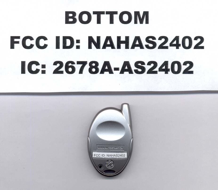
NAHAS2402
Jun 19, 20074 BUTTON OOK REMOTE
Equipment Class
DSC - Part 15 Security/Remote Control Transmitter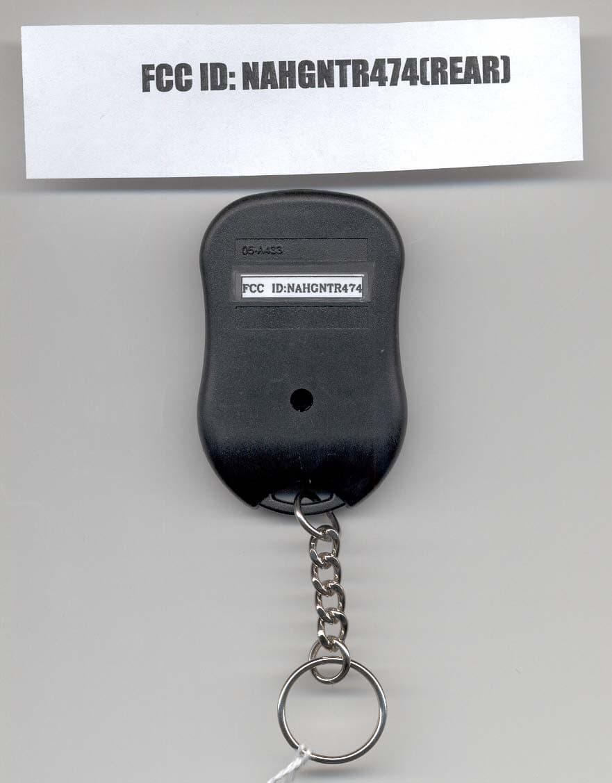
NAHGNTR474
Feb 14, 2007DECURITY TRANSMITTER
Equipment Class
DSC - Part 15 Security/Remote Control Transmitter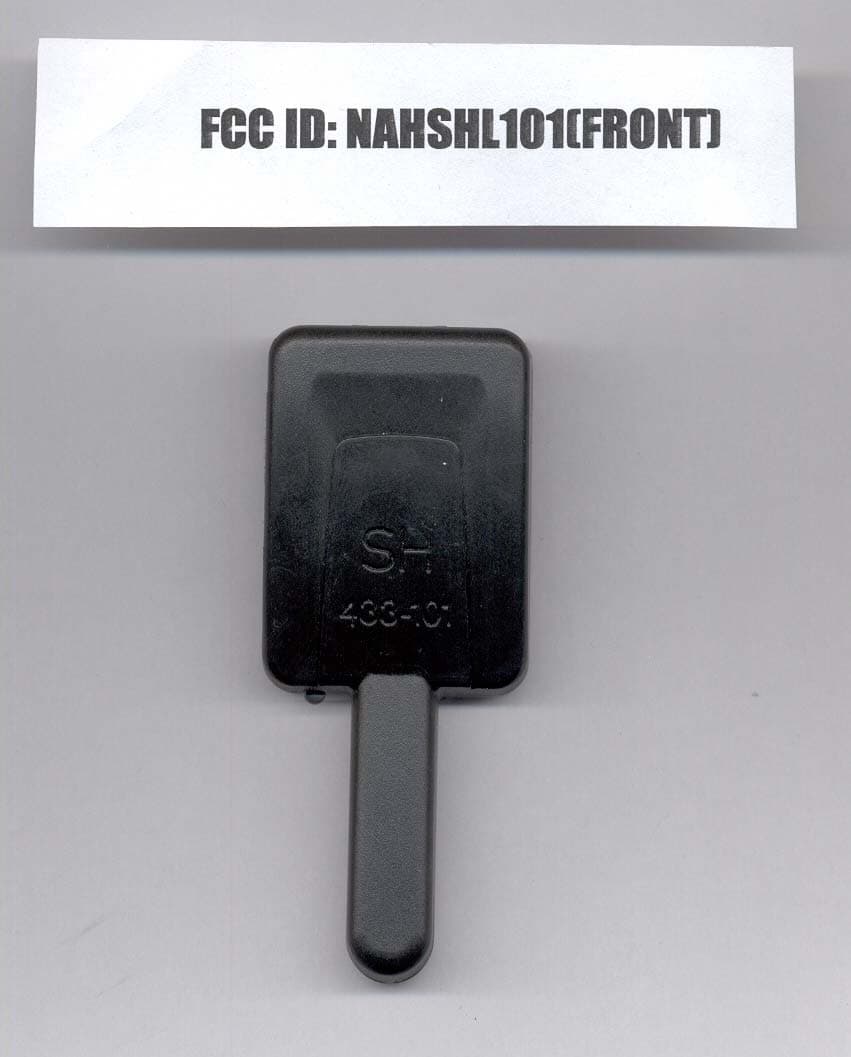
NAHSHL101
Feb 14, 2007SECURITY RECEIVER
Equipment Class
CYY - Communications Receiver used w/Pt 15 Transmitter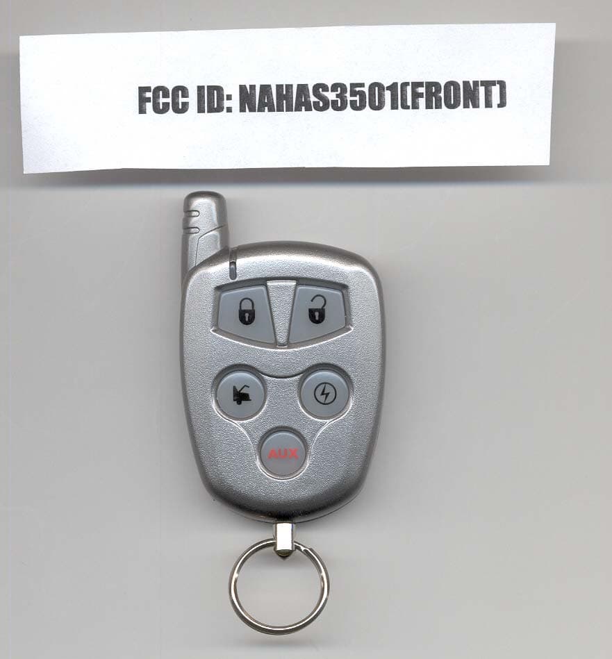
NAHAS3501
Jan 24, 2007SECURITY TRANSMITTER
Equipment Class
DSC - Part 15 Security/Remote Control Transmitter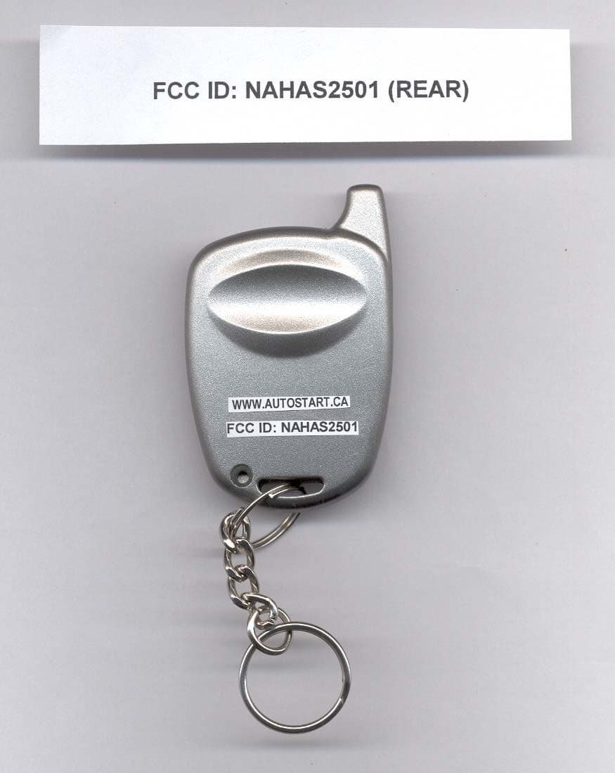
NAHAS2501
Sep 25, 2006REMOTE CONTROL TRANSMITTER
Equipment Class
DSC - Part 15 Security/Remote Control Transmitter